


1/6 F-105 Build Thread
 11-26-2018, 06:48 PM
#176

Thread Starter
My Feedback: (20)
That was a stab system designed by Fighteraces in the UK. It looks really good but the stabs are not easily removed for transport. I'm discussing with OIi at Ultimate Jets about using one of his systems for the F-105. More info to come soon I hope.
 11-26-2018, 07:08 PM
#177
Thread Starter
My Feedback: (20)
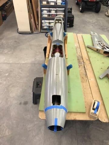
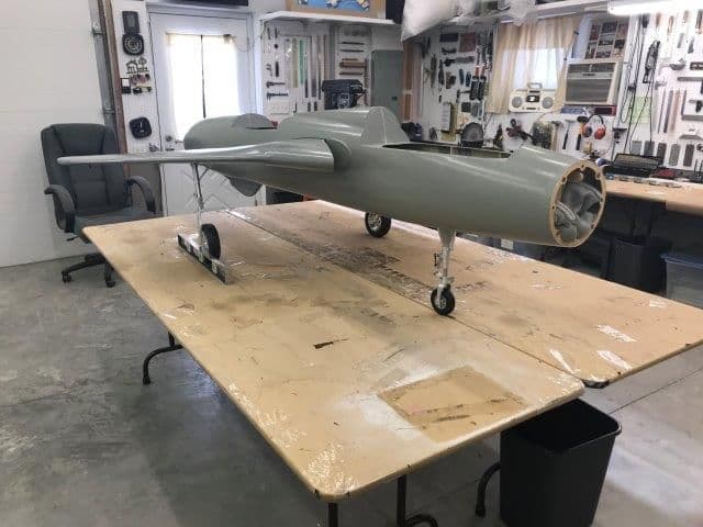
I kept having trouble lining up the turbine and pipe in the center of the fuse. Nothing seemed to line up when I centered it inside the fuse. So I ran a thread from nose to tail to find the "center" of the fuse. Boy was I surprised.
I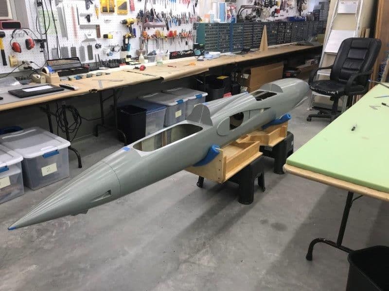
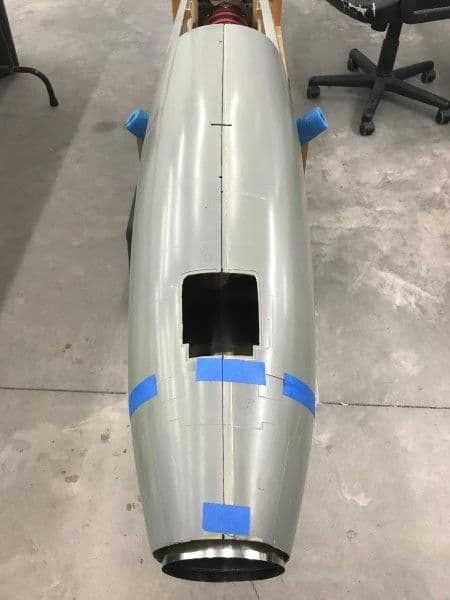
Fuse put on floor so I could look down at it from "above"
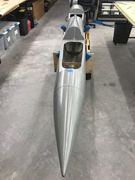
Thread taped to center of the nose and run to center of the tail
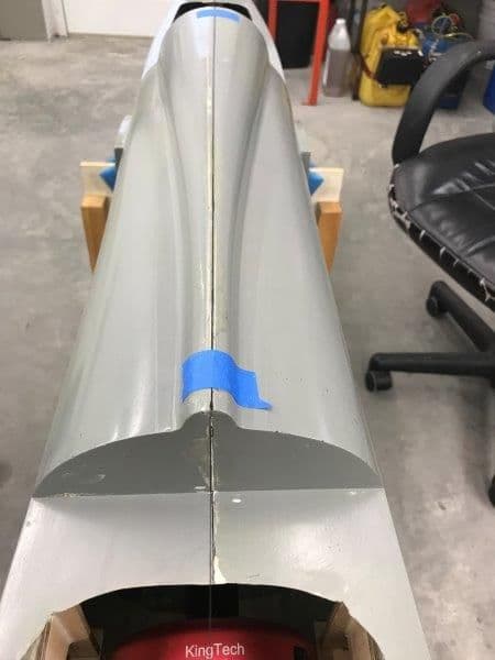
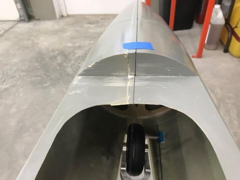
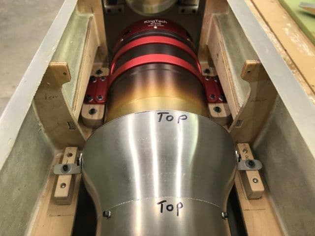
Engine hatch looking forward. I taped the thread to the fuse after I stretched it out to keep it from moving on the curved turtledeck.
Cockpit looking forward. The fiberglass seam is not the center line.
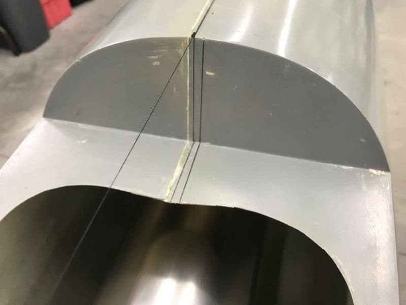
Aft end of engine hatch. The center of the hatch is the right line, the thread is the center of the fuse. Way off. No wonder centering the turbine inside the fuse did not line up with the center line of the whole fuse.
Rear fuse not symmetrical, its fatter on the left side.
So now armed with the real center line of the fuse the turbine and pipe have to be slightly offset to the right inside the engine bay to be on the total center line of the fuse. Looks a little goofy in the the engine hatch but finally looks correct from a birds eye view of the whole fuse.
I
Fuse put on floor so I could look down at it from "above"
Thread taped to center of the nose and run to center of the tail
Engine hatch looking forward. I taped the thread to the fuse after I stretched it out to keep it from moving on the curved turtledeck.
Cockpit looking forward. The fiberglass seam is not the center line.
Aft end of engine hatch. The center of the hatch is the right line, the thread is the center of the fuse. Way off. No wonder centering the turbine inside the fuse did not line up with the center line of the whole fuse.
Rear fuse not symmetrical, its fatter on the left side.
So now armed with the real center line of the fuse the turbine and pipe have to be slightly offset to the right inside the engine bay to be on the total center line of the fuse. Looks a little goofy in the the engine hatch but finally looks correct from a birds eye view of the whole fuse.
11-26-2018, 07:37 PM
#178
Thread Starter
My Feedback: (20)
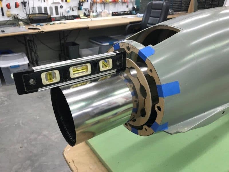
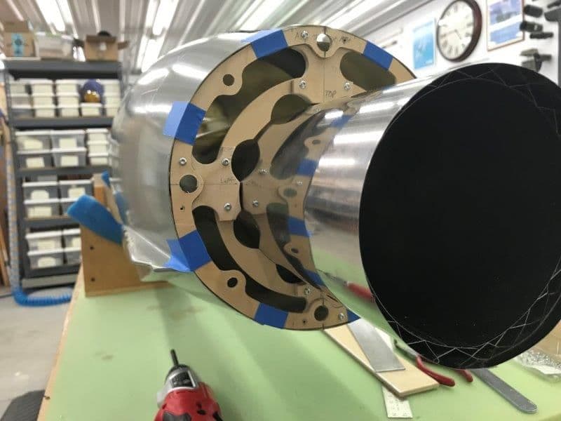
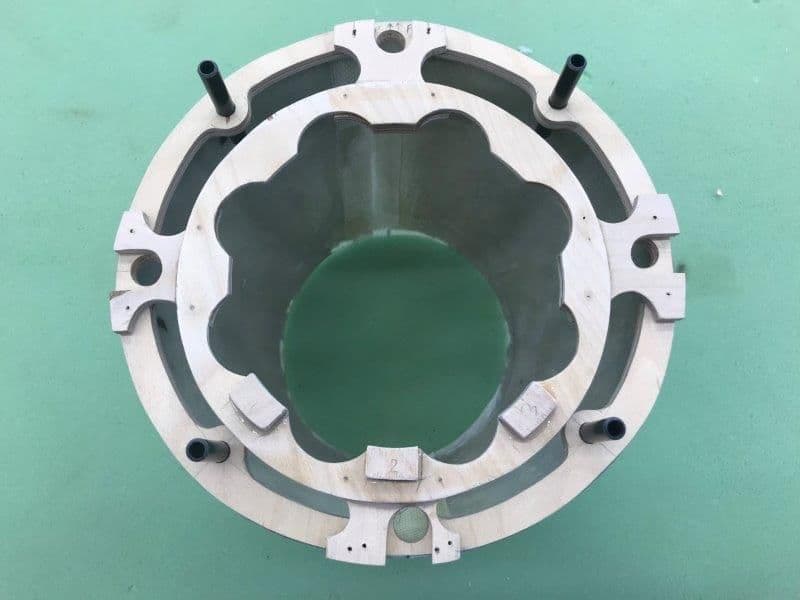
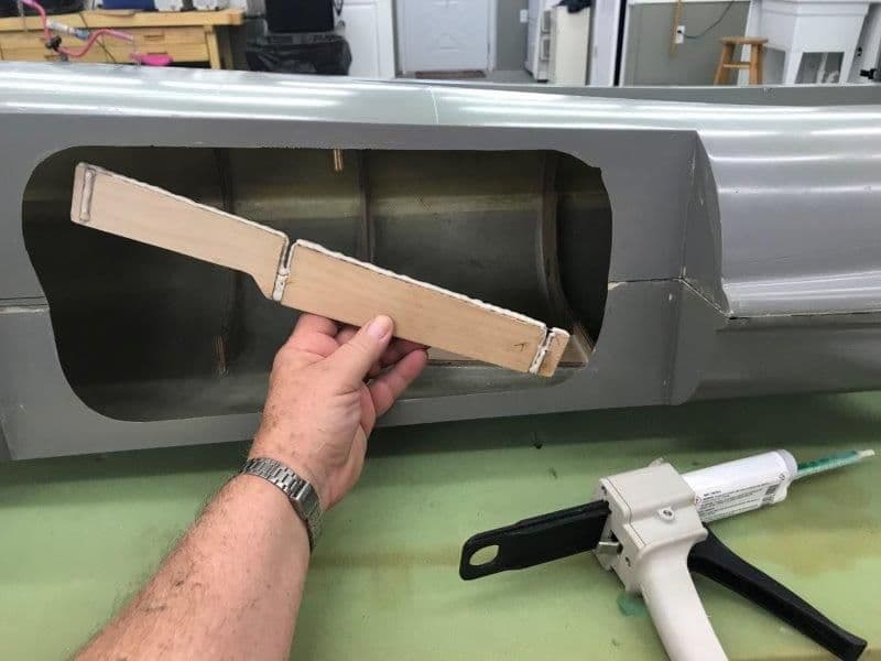
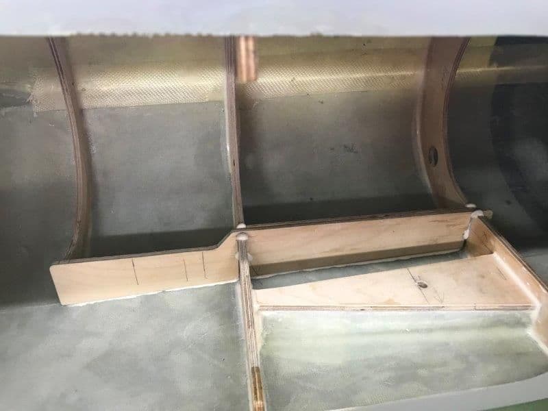
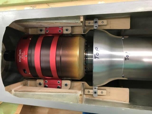
Pipe aft support ring fabricated and installed. The custom pipe has an additional inner zig zag support ring 173 mm forward from the aft end where the plywood support ring is located on the aft fuse former. This is to keep the outer tube from crushing from the weight of the pipe on the support ring. The fiberglass nozzle fits over the pipe and fastens to the aft fuse former. If I ever get an AB LED ring it will live inside the fiberglass nozzle behind the plywood support ring.
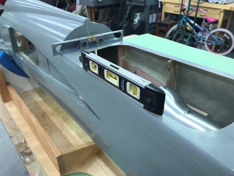
Fuse leveled in both directions. Turbine checked for level on rails.
I taped the aft former in place because I don't want to glue it in until I get all the stab, rudder, and linkages installed in the fuse. I need the wide opening to get my hands and tools inside to install all the parts. Plywood support ring is set to level the pipe
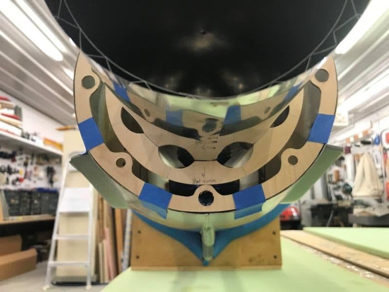
Ply support ring rests on the aft fuse former at the correct height.
Top and bottom brackets fabricated and held on with screws until alignment can be checked.
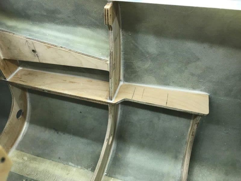
Final support ring and brackets after alignment is verified. Its all off center to account for the wacky shape of the fuse. The brackets will be epoxied to the ring and screws removed after everything is checked and verified.
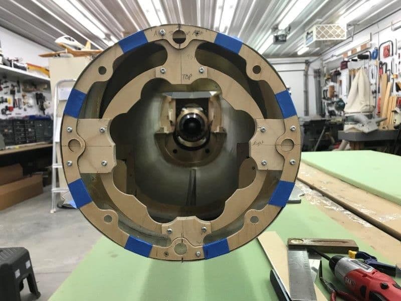
Pipe support ring in place
Pipe alignment checked
Nozzle cone installed and pipe in center of the offset hole.
Fuse leveled in both directions. Turbine checked for level on rails.
I taped the aft former in place because I don't want to glue it in until I get all the stab, rudder, and linkages installed in the fuse. I need the wide opening to get my hands and tools inside to install all the parts. Plywood support ring is set to level the pipe
Ply support ring rests on the aft fuse former at the correct height.
Top and bottom brackets fabricated and held on with screws until alignment can be checked.
Final support ring and brackets after alignment is verified. Its all off center to account for the wacky shape of the fuse. The brackets will be epoxied to the ring and screws removed after everything is checked and verified.
Pipe support ring in place
Pipe alignment checked
Nozzle cone installed and pipe in center of the offset hole.
11-26-2018, 07:43 PM
#179
Thread Starter
My Feedback: (20)
That's it for this week. Somewhere about two years ago I must have wanted to buy a jet or something big for a jet so my wife agreed if she could buy a Disney Cruise with the grand kids. I guess I said OK and now the bill is due. We will be spending the weekend on the Mouse Boat somewhere other than the workshop. Back next week to continue.
Gary
Gary
 12-07-2018, 05:22 PM
#182
Thread Starter
My Feedback: (20)
Everyone safely returned from the the Disney Cruise. It was great, all had fun, and the food was awesome. My favorite was the cold sea food bar with all you can eat shell fish and crab legs. Otherwise, it was SEE food and eat. We only lost one grand kid one time. The 2 1/2 decided to take a tour of the ship by himself when mom was in bathroom. Out the door he went and his 1 1/2 sister just pointed to the door when asked where did your brother go. Some nice crew members escorted him back after a few minutes. I did not think much about the F-105 because we were too busy tracking 6 grand kids during the week. Disney does a nice job on their ship. Highly recommended.
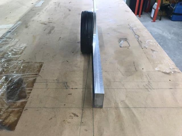
Back in the shop today. I got the main landing gear back from Mitch at Down and Locked after a mod recommended by Bob Rullie. We replaced the steel pin in the struts with a titanium pin so it would be stronger to resist bending and also lighter. I also had Mitch use 4 set screws where the split roll pins went in to hold the lower strut on the pin. This will allow me to adjust the tow angle when the gear is extended.
When tow angle is adjusted for straight ahead the leading edge of the tire will be raised in the gear well slightly above level. I will have to see how this affects the gear doors. Also the main gear strut door will have a slight twist and cause more drag when extended and during retraction. All future problems to be solved.
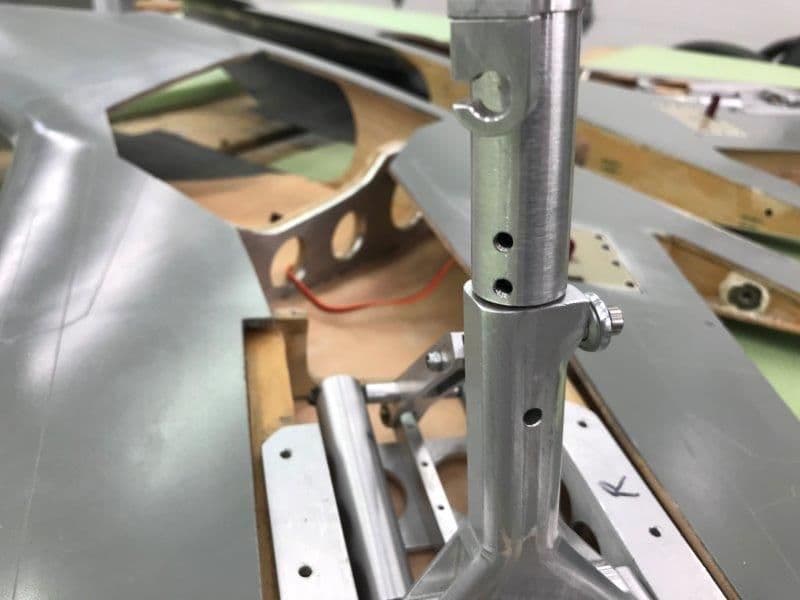
Set screws instead of split roll pins to allow tow angle to be adjusted on the lower strut.
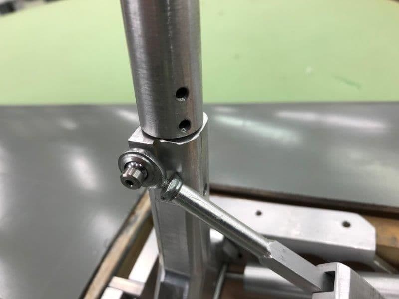
Same on opposite side of strut
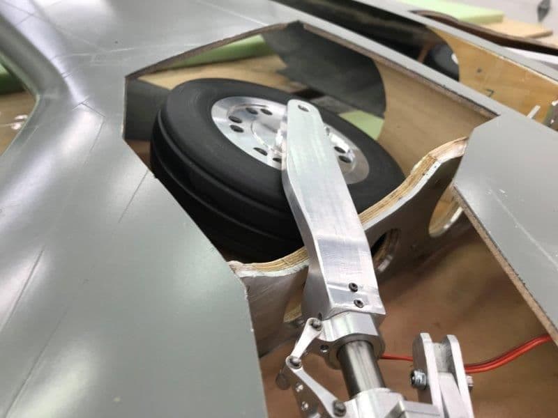
When tow angle is set straight the leading edge of tire is raised when in wheel well. I will have to assemble the jet and set the proper tow angle to see just how much.
Back in the shop today. I got the main landing gear back from Mitch at Down and Locked after a mod recommended by Bob Rullie. We replaced the steel pin in the struts with a titanium pin so it would be stronger to resist bending and also lighter. I also had Mitch use 4 set screws where the split roll pins went in to hold the lower strut on the pin. This will allow me to adjust the tow angle when the gear is extended.
When tow angle is adjusted for straight ahead the leading edge of the tire will be raised in the gear well slightly above level. I will have to see how this affects the gear doors. Also the main gear strut door will have a slight twist and cause more drag when extended and during retraction. All future problems to be solved.
Set screws instead of split roll pins to allow tow angle to be adjusted on the lower strut.
Same on opposite side of strut
When tow angle is set straight the leading edge of tire is raised when in wheel well. I will have to assemble the jet and set the proper tow angle to see just how much.
12-07-2018, 05:35 PM
#183
Thread Starter
My Feedback: (20)
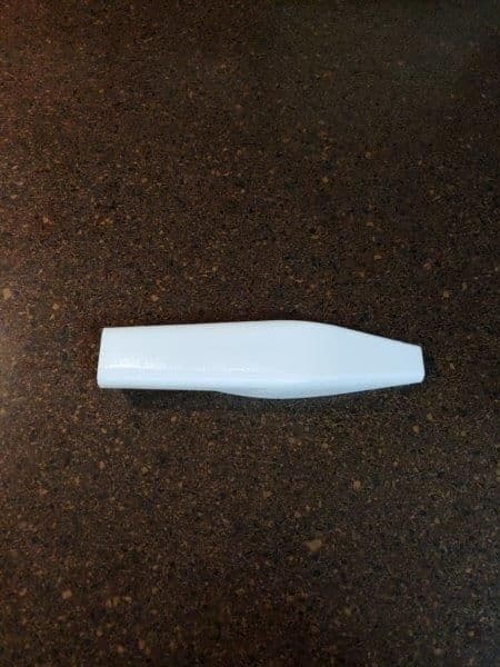
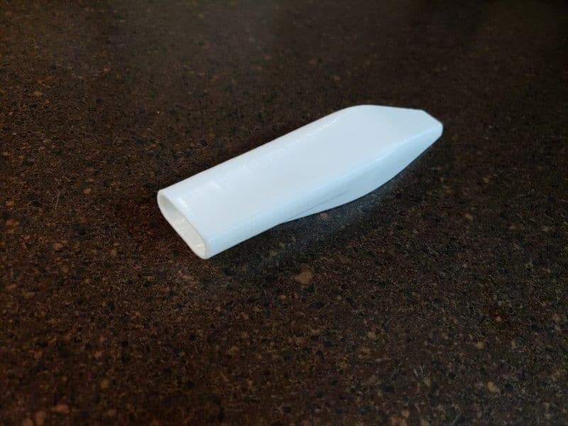
Small progress on pipe support ring and 3D printed air scoops
Pipe support ring finished and screws removed
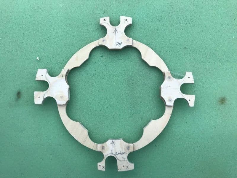
Plywood brackets epoxied to ring and holes filled.
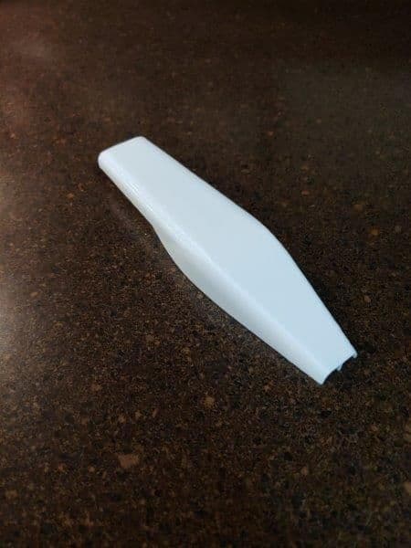
Keith modified the air scoop shape and it looks great now.
Pipe support ring finished and screws removed
Plywood brackets epoxied to ring and holes filled.
Keith modified the air scoop shape and it looks great now.
12-10-2018, 05:35 PM
#184
Thread Starter
My Feedback: (20)
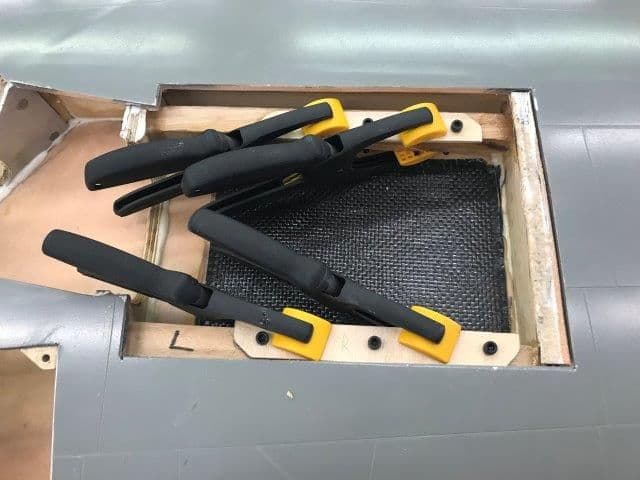
Glued in turbine mounts with hysol.
Initial application of hysol to rail ready to insert into formers
Initial rail position
Final fill in and hysol filets

Clamped plywood plate across both rails to keep them aligned during cure.
Initial application of hysol to rail ready to insert into formers
Initial rail position
Final fill in and hysol filets
Clamped plywood plate across both rails to keep them aligned during cure.
12-10-2018, 06:02 PM
#185
Thread Starter
My Feedback: (20)
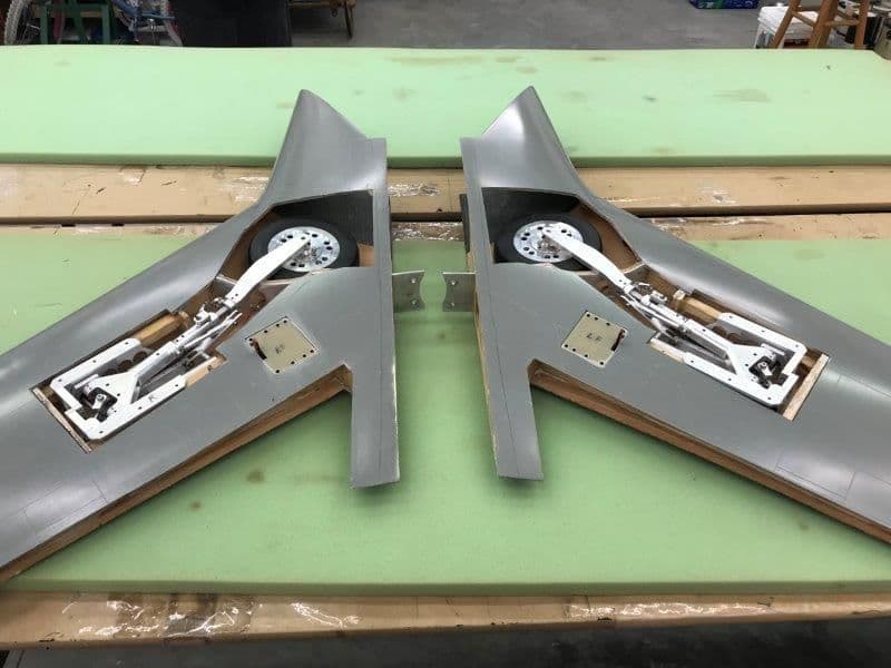
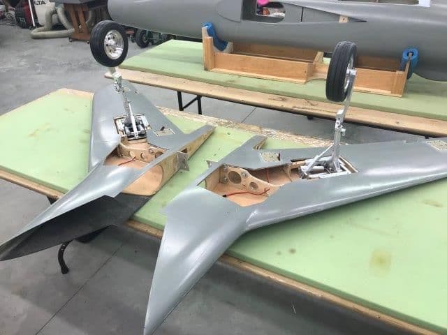
As mentioned before in the thread the left wing is thinner than the right wing. So far all builders I have spoken with have ground out the airex material inside the top wing skin to make the gear well deep enough to mount the gear and still get it inside the wing so the gear well covers will fit flush with the bottom wing skin.
So here we go.
The problem area was marked, at least it was where i thought the problem was.
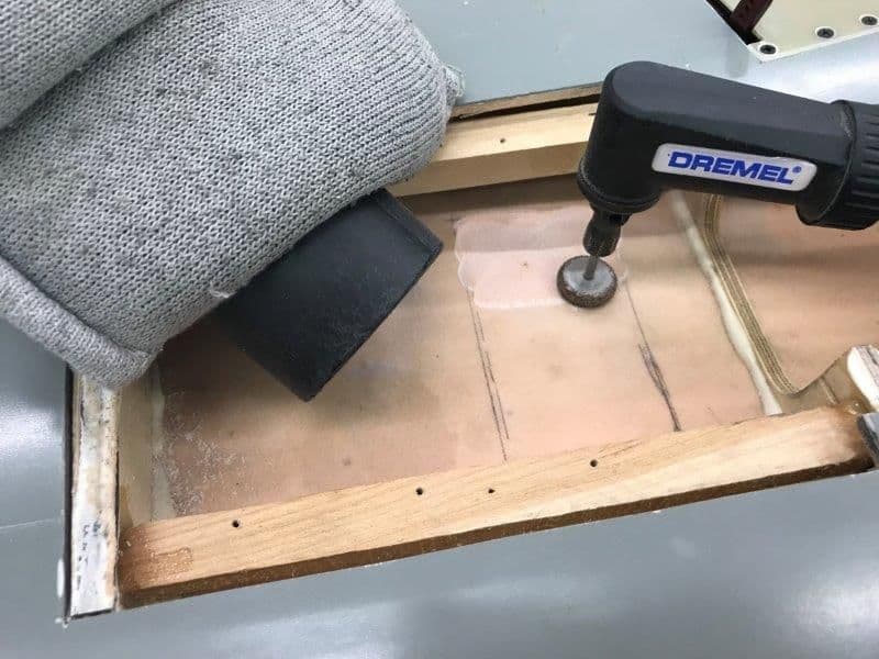
Vacuum dust collection and permagrit dremel grinder going. After this area was removed I did a dry fit and found the rest of the gear mount frame was still touching the top wing skin.
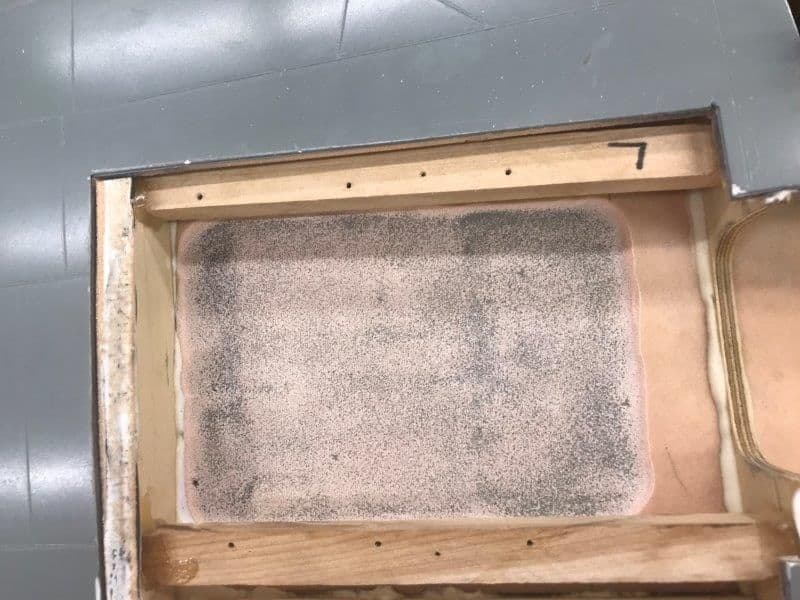
So I removed the entire area. This left the upper wing skin paper thin and very flexible. I was afraid I would punch a hole in it with something eventually.
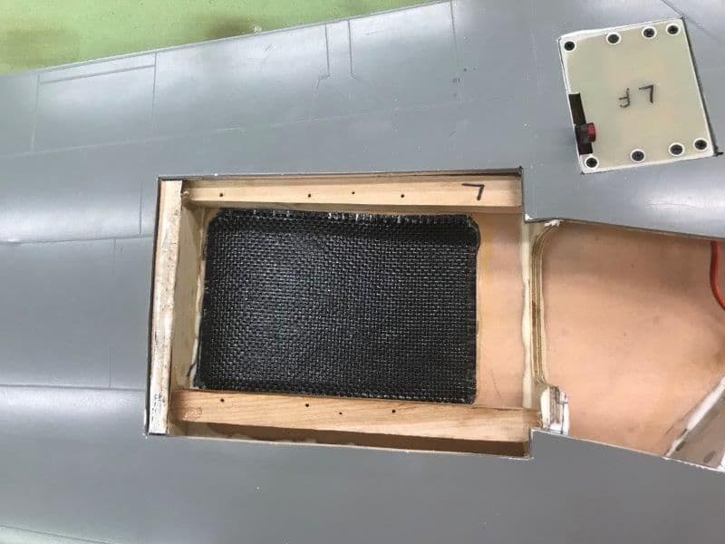
I placed a layer of carbon fiber cloth in the area and it really stiffened up the skin after epoxy cure.
Even after removing as much material as possible I still had to shim the gear up 3/32" to get it off the inside of the upper wing skin. At least the trailing edge side (right in the photo) is now below the surface of the bottom wing skin and a proper gear well cover can now be attached. The gear is temporarily mounted with servo screws so I can mount the wings and check the gear toe angle.
I don't worry much any more about symmetry, straight lines, or looks with this pile of parts. Its just "git-er-done" now.
So here we go.
The problem area was marked, at least it was where i thought the problem was.
Vacuum dust collection and permagrit dremel grinder going. After this area was removed I did a dry fit and found the rest of the gear mount frame was still touching the top wing skin.
So I removed the entire area. This left the upper wing skin paper thin and very flexible. I was afraid I would punch a hole in it with something eventually.
I placed a layer of carbon fiber cloth in the area and it really stiffened up the skin after epoxy cure.
Even after removing as much material as possible I still had to shim the gear up 3/32" to get it off the inside of the upper wing skin. At least the trailing edge side (right in the photo) is now below the surface of the bottom wing skin and a proper gear well cover can now be attached. The gear is temporarily mounted with servo screws so I can mount the wings and check the gear toe angle.
I don't worry much any more about symmetry, straight lines, or looks with this pile of parts. Its just "git-er-done" now.
12-10-2018, 06:22 PM
#186
Thread Starter
My Feedback: (20)
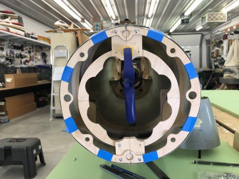
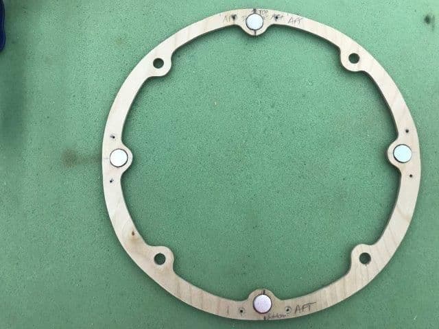
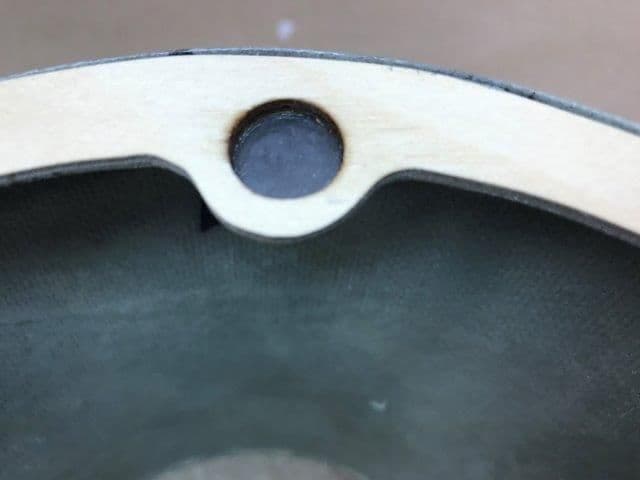
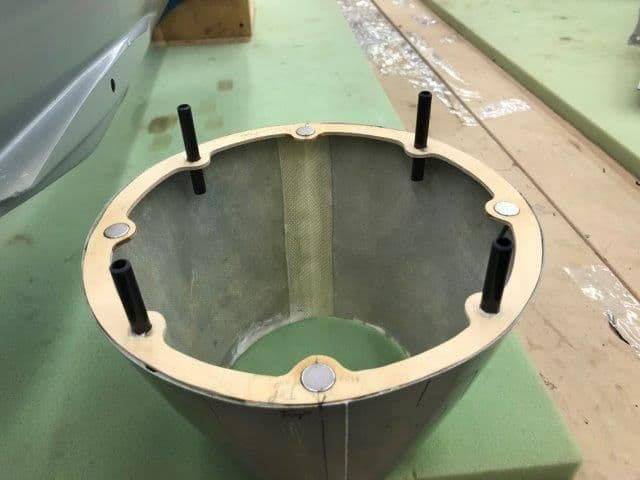
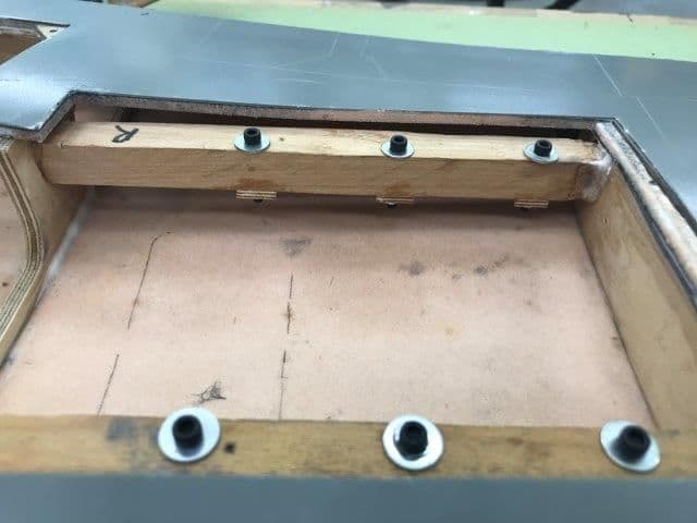
The nozzle and rear pipe support rings are held in place by magnets. This allows the nozzle and pipe to be easily removed if needed to get to the stab mechanics inside the fuse. These magnets are so strong I only put two on the nose cone because it was too hard to pull off. On the rear I'm using all 4 positions since they are holding the rear pipe support.
The back side of the former is capped with a very thin piece of G10 attached with thin CA to provide a backing for the epoxy pocket that holds the magnet in the hole.
The magnets are then epoxied in the hole from the opposite side. These are 1/8" thick in 1/8" thick ply.
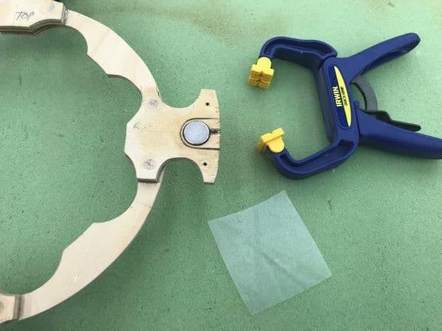
The pipe support ring has 1/4" thick tabs so there are 2 magnets stacked together here to have the magnet flush with both sides. The G10 is glued on the bottom with CA and the clamp keeps them together and squeezes the excess epoxy out. The plastic sheet keeps the epoxy from sticking to the clamp. The pipe support ring is sandwiched between the rear fuse former and the front nozzle former and can not move. If I really get worried about it I will secure it with a servo screw.
The back side of the former is capped with a very thin piece of G10 attached with thin CA to provide a backing for the epoxy pocket that holds the magnet in the hole.
The magnets are then epoxied in the hole from the opposite side. These are 1/8" thick in 1/8" thick ply.
The pipe support ring has 1/4" thick tabs so there are 2 magnets stacked together here to have the magnet flush with both sides. The G10 is glued on the bottom with CA and the clamp keeps them together and squeezes the excess epoxy out. The plastic sheet keeps the epoxy from sticking to the clamp. The pipe support ring is sandwiched between the rear fuse former and the front nozzle former and can not move. If I really get worried about it I will secure it with a servo screw.
12-11-2018, 03:45 PM
#187
Thread Starter
My Feedback: (20)
More magnets...
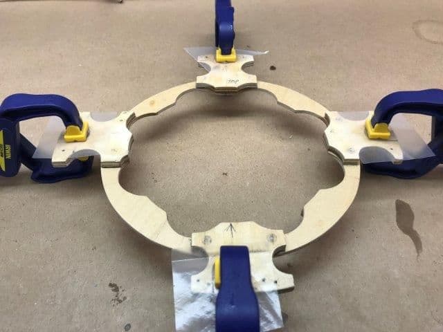
Clamping magnets in pipe support ring during epoxy cure
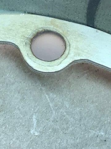
G10 back cover on magnet hole
G10 makes a nice magnet pocket to apply epoxy in and then insert magnets
Single magnets did not require clamping during cure.
Clamping magnets in pipe support ring during epoxy cure
G10 back cover on magnet hole
G10 makes a nice magnet pocket to apply epoxy in and then insert magnets
Single magnets did not require clamping during cure.
12-11-2018, 04:09 PM
#188
Thread Starter
My Feedback: (20)
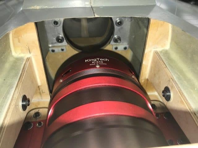
Mounted turbine and pipe today.
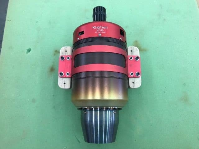
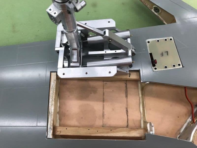
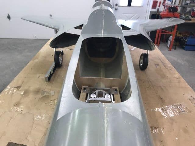
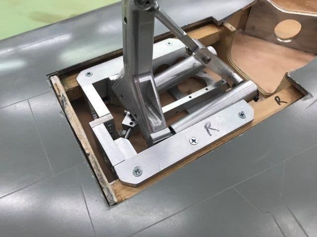
Top view of turbine riser mounts. Since I had to raise the turbine and pipe above the level that was planned in the provided parts to fit correctly, I mounted the turbine on 3/4" U shaped risers. The U shape is to allow access to the mounting bolts since access to the normal mounting bolts are blocked under the wing root inserts on the inside of the turbine bay.
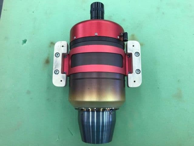
Bottom view, turbine mounting bolts are recessed to allow plywood risers to sit flat on the turbine rails.
White string stretched across the turbine hatch area to show true centerline of fuse...NOT the turbine hatch. There is about 1/4" offset to the right of the fuse centerline in the hatch area.
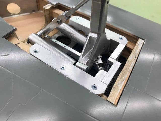
After several hours of staring, marking, measuring, rechecking, drilling, fixing and fussing I finally got the turbine and pipe mounted with bolts and blind nuts.
The turbine can now be removed with the normal 4 bolts. The pipe only has 2 bolts. Counter sunk servo screws hold the pipe risers in place when the pipe is removed. I planned to have some adjustment room fore and aft in case of future engine and pipe changes and I wanted to keep the turbine rails unobstructed since they are permanently glued in.
Finally got it all lined up using the very precise and highly technical "TLAR" method.
Top view of turbine riser mounts. Since I had to raise the turbine and pipe above the level that was planned in the provided parts to fit correctly, I mounted the turbine on 3/4" U shaped risers. The U shape is to allow access to the mounting bolts since access to the normal mounting bolts are blocked under the wing root inserts on the inside of the turbine bay.
Bottom view, turbine mounting bolts are recessed to allow plywood risers to sit flat on the turbine rails.
White string stretched across the turbine hatch area to show true centerline of fuse...NOT the turbine hatch. There is about 1/4" offset to the right of the fuse centerline in the hatch area.
After several hours of staring, marking, measuring, rechecking, drilling, fixing and fussing I finally got the turbine and pipe mounted with bolts and blind nuts.
The turbine can now be removed with the normal 4 bolts. The pipe only has 2 bolts. Counter sunk servo screws hold the pipe risers in place when the pipe is removed. I planned to have some adjustment room fore and aft in case of future engine and pipe changes and I wanted to keep the turbine rails unobstructed since they are permanently glued in.
Finally got it all lined up using the very precise and highly technical "TLAR" method.
12-11-2018, 04:21 PM
#189
Thread Starter
My Feedback: (20)
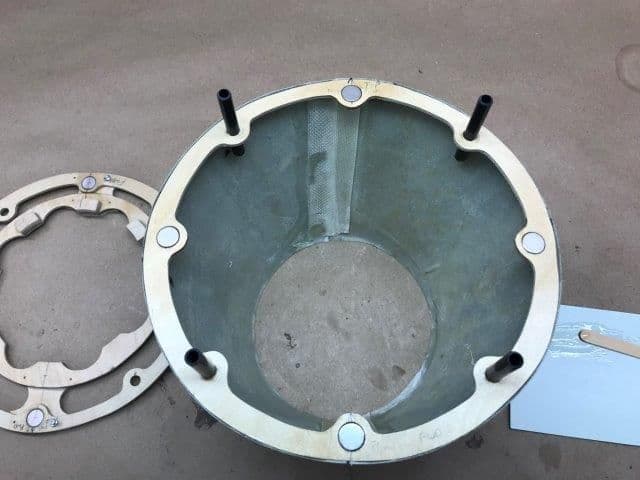
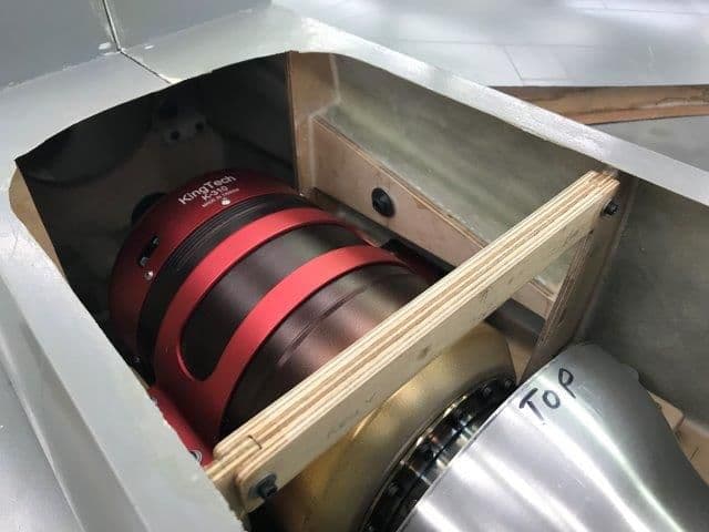
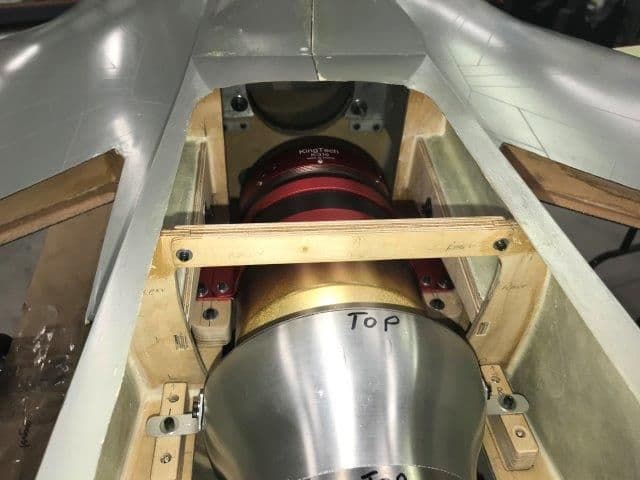
Magnets hold nozzle and aft pipe support ring in place
Nozzle cone removed
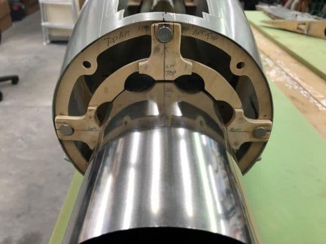
Aft pipe support ring ready to pull off. No tools required. Magnets are so strong I may take some out after rear former is finally glued in and a proper test can be made. I am waiting to glue the aft former in the fuse till I get the stabs mounted.
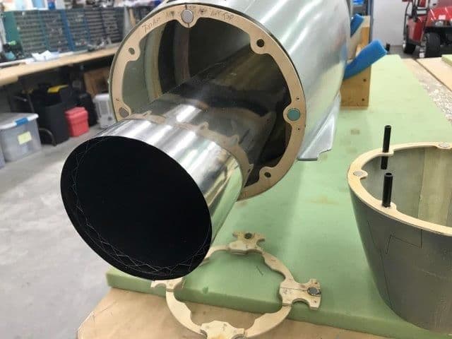
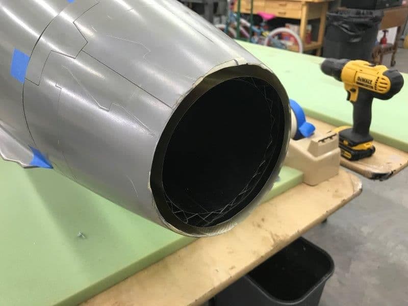
Pipe support ring removed and pipe is ready to slide out with only removing 2 bolts in front. Removing the pipe will be necessary to remove and install the stabs if needed.
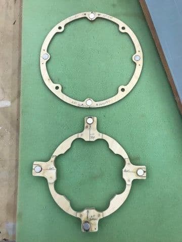
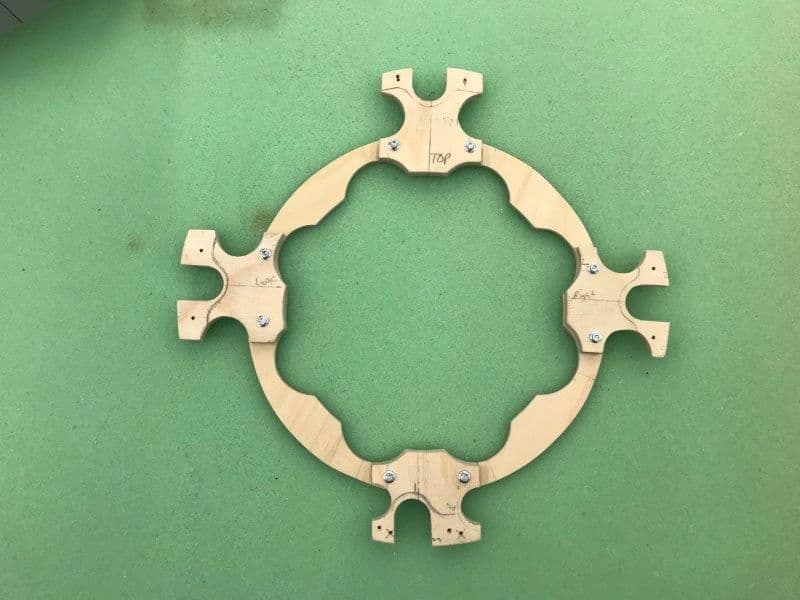
Final shape of pipe support ring after several design changes and mods. It's scratch building...It will paint up pretty!
Nozzle cone removed
Aft pipe support ring ready to pull off. No tools required. Magnets are so strong I may take some out after rear former is finally glued in and a proper test can be made. I am waiting to glue the aft former in the fuse till I get the stabs mounted.
Pipe support ring removed and pipe is ready to slide out with only removing 2 bolts in front. Removing the pipe will be necessary to remove and install the stabs if needed.
Final shape of pipe support ring after several design changes and mods. It's scratch building...It will paint up pretty!
12-12-2018, 05:45 PM
#190
Thread Starter
My Feedback: (20)
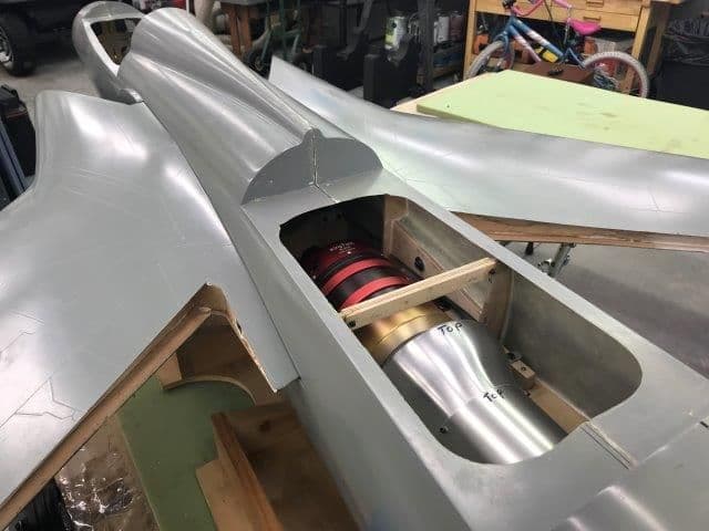
I did the first "full dress" wing mount exercise to test how hard it was to mount the wings with the turbine and pipe in place. Other than being inconvenient and a pain, it was not as bad as I was afraid it would be.
First I had to slant drill the wing root bolt holes to get the 2" long wing bolts in over the turbine. I quickly discovered you had to insert these bolts through the fuse sides before you inserted the wings or they would not go in because of the angle over the turbine. No big problem just have to remember to do it first. Getting the main bolts in on the wing former was not bad, you just have to insert them by feel and then jiggle the wing while turning to engage the blind nut threads.
After engaging the 4 main bolts you next engage the wing root bolts into the wing root blind nuts. After that you tighten everything down with a ball drivers due to the offset angles.
All this can be done with the fuse former bridge in place but I found it much easier to remove the bridge to allow my arm to more easily get to the forward bolts.
After the wings are installed I replaced the fuse former bridge which is fairly easy to do.
Last edited by Viper1GJ; 12-12-2018 at 05:48 PM.
12-12-2018, 06:14 PM
#191
Thread Starter
My Feedback: (20)
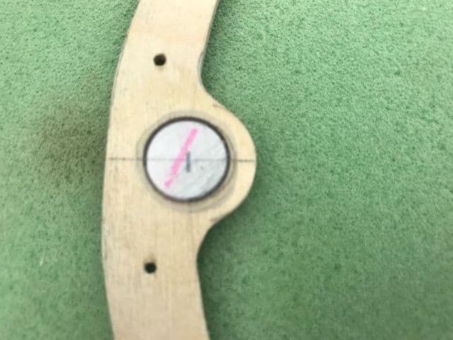
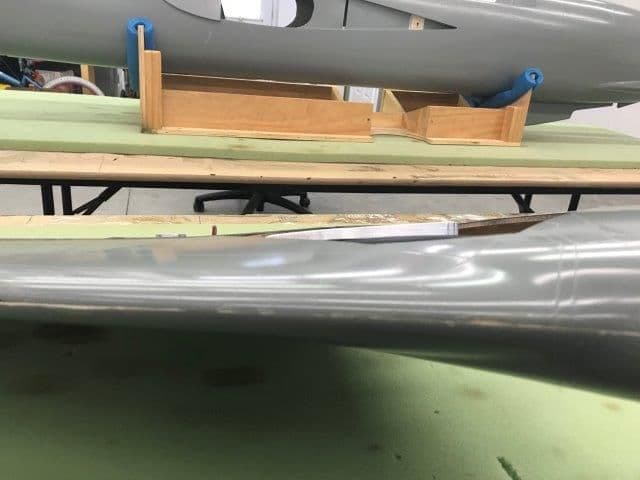
The purpose of the wing mounting drill was to set the proper toe angle of the main gear.
The jet was aligned on the table so the tires were on the markings made back in SEP. The set screws on the lower struts were loosened and struts rotated to align tires with the parallel lines on the table.
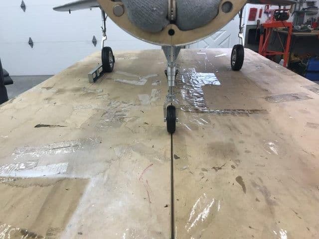
Nose tire and fuse tail skid were aligned over the split between tables.
A straight edge bubble level was placed next to the tires to align the tires to the lines.
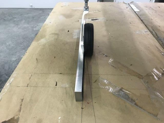
Right tire aligned with parallel line and all 4 lower strut set screws tightened.
Same for left tire. The roll test on the table was perfect. Much better than when each tire had the gross toe in angle.
With this step in the build, I felt like I had slain one of the big dragons on this jet. Getting the gear mod by Mitch at Down and Locked replacing the split roll pins with 4 set screws allowed the toe angle to be adjusted. This made the gear straight without major machine work to modify the rotating angle of the retract. I was very happy how this came out.
The jet was aligned on the table so the tires were on the markings made back in SEP. The set screws on the lower struts were loosened and struts rotated to align tires with the parallel lines on the table.
Nose tire and fuse tail skid were aligned over the split between tables.
A straight edge bubble level was placed next to the tires to align the tires to the lines.
Right tire aligned with parallel line and all 4 lower strut set screws tightened.
Same for left tire. The roll test on the table was perfect. Much better than when each tire had the gross toe in angle.
With this step in the build, I felt like I had slain one of the big dragons on this jet. Getting the gear mod by Mitch at Down and Locked replacing the split roll pins with 4 set screws allowed the toe angle to be adjusted. This made the gear straight without major machine work to modify the rotating angle of the retract. I was very happy how this came out.
Last edited by Viper1GJ; 12-12-2018 at 06:18 PM.
12-12-2018, 06:42 PM
#192
Thread Starter
My Feedback: (20)
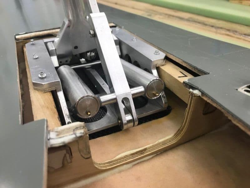
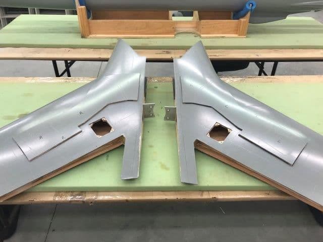
The next question was how the proper toe angle would retract into the gear wells and could the gear doors be made to close when retracted.
Wing removed and waiting for retract fold test into gear wells
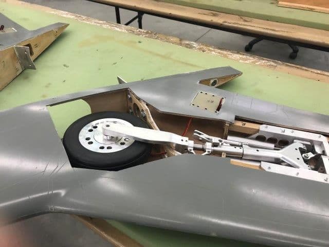
Right main folded in and seems to fit OK.
Leading edge of tire slightly higher in gear well but I think I can make the gear doors go over it
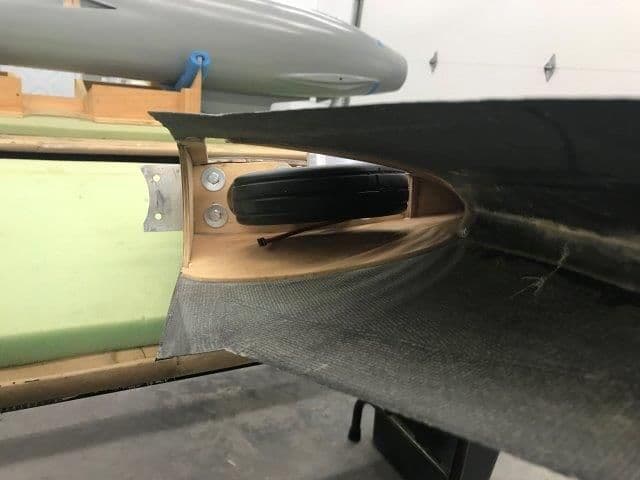
Right main inside the well from front wing intake. Leading edge is slightly high and will take a mod on the gear door to cover it.
Left main folded into the gear well.
Left tire mostly in well
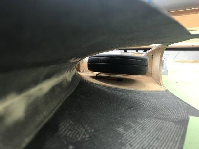
Left tire leading edge slightly lower than the right side.
Over all I am pleased with the gear mods. The toe in angle is fixed. The main strut door angle when extended is acceptable. It will take a little shaping work on the bottom of the wing around the gear well to cover the tire bump but I think that is workable. Its just model airplane grunt work not re engineering the gear mechanics and metal machine work. Overall I think I can make the gear retraction mechanics and doors work. The real question is can the air system make it work. TBD.
Wing removed and waiting for retract fold test into gear wells
Right main folded in and seems to fit OK.
Leading edge of tire slightly higher in gear well but I think I can make the gear doors go over it
Right main inside the well from front wing intake. Leading edge is slightly high and will take a mod on the gear door to cover it.
Left main folded into the gear well.
Left tire mostly in well
Left tire leading edge slightly lower than the right side.
Over all I am pleased with the gear mods. The toe in angle is fixed. The main strut door angle when extended is acceptable. It will take a little shaping work on the bottom of the wing around the gear well to cover the tire bump but I think that is workable. Its just model airplane grunt work not re engineering the gear mechanics and metal machine work. Overall I think I can make the gear retraction mechanics and doors work. The real question is can the air system make it work. TBD.
Last edited by Viper1GJ; 12-12-2018 at 06:46 PM.
12-12-2018, 07:27 PM
#193
Regarding the wing retaining screws: why don't you just glue some threaded rod into the wing (or install the screws from the other side, and glue them in place) and use a nut on the inside of the fuse? I've done this before with great success: to tighten the bolt you can just use a ratchet wrench and it's super quick. No need to remove the former bridge and do weird gymnastics to get the screws in place.
12-13-2018, 07:47 AM
#194

I had a thought along the same lines as maury, but I was thinking more of a hand tightened knurled head nut rather than something requiring a ratchet.
Seems like your current approach will work though, hard to say which would be more or less of a pain.
Seems like your current approach will work though, hard to say which would be more or less of a pain.
12-13-2018, 03:20 PM
#195
Thread Starter
My Feedback: (20)
Thanks for the recommendations. I think the problem with any kind of glued in stud or threaded rod is the inset wing root pocket in the fuse. The last 3/4" of travel when the wing is inserted is inside the pocket does not allow any fore or aft movement to get the spar tab over a fixed bolt stud. The way Bob has it designed is the wing has to slide into the inset pocket and the spar tab slides on the back side of the wing former in contact with it. This is why you have to put the bolt in after the wing is fully inserted into the fuse pocket.
Also once the wing is in you lose access to the front of the former because of the wing intakes which I have not posted any photos of or installed yet. It may be possible to insert a bolt by hand from the front of the former by putting your hand thru the air hole in front of the turbine and pushing it backwards through the mounting hole. Then a nut of some kind could be screwed on the back side, knurled or wing type. The holes are close to the edge of the intake hole so they cant be too big.
I've, been concerned from the beginning about the entire weight of the jet, G forces, and landing forces are transmitted into the wing former. It is just 1/2' aircraft ply but the holes are near the edge of the air intake hole. I have been thinking about laminating a carbon fiber "donut" on the front side of the former to give some more "beef" to the main foundation of the entire jet.
Last edited by Viper1GJ; 12-13-2018 at 03:25 PM.
12-13-2018, 04:01 PM
#196
Thread Starter
My Feedback: (20)
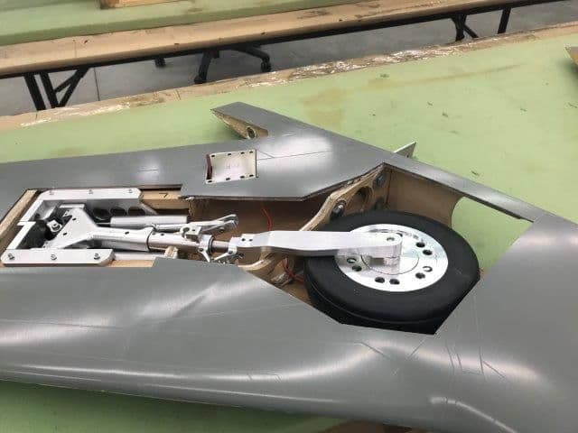
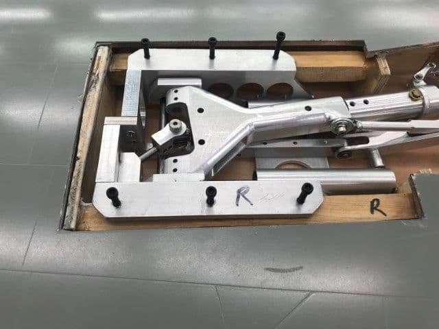
Mounted main landing gear to the gear rails.
First I replaced 2 hex head bolts with counter sunk flat head bolts to make more clearance for the tire in gear well
Drilled left wing mounts and laminated the 3/32" ply spacers on to rails
Drilled right wing mounts for 6-32 bolts
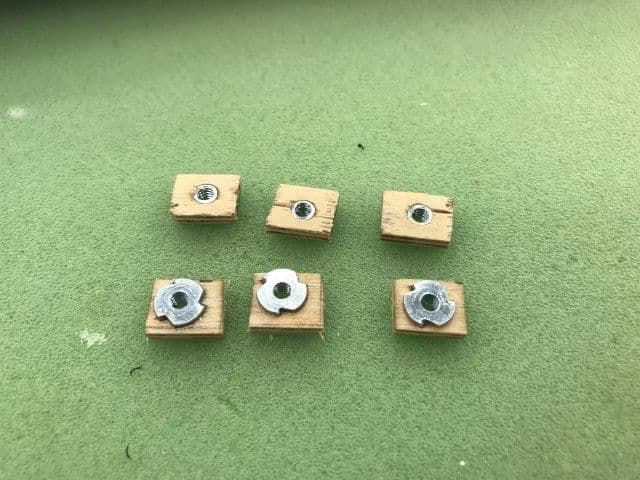
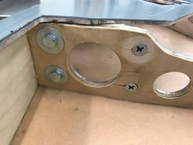
I could not get the blind nuts into the maple beam mounts and I did not want to drill an oversize hole in the mounts so I sunk the blind nuts into 1/8" ply squares
Blind nuts epoxied to bottom of gear mount rails. I use vaseline on bolt threads to keep epoxy from locking bolts in.
Aluminum gear mounts countersunk and gear installed with flat head bolts to give clearance for gear door cover.
Same of left side
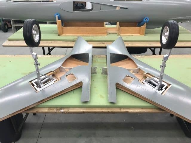
Main gear mounted
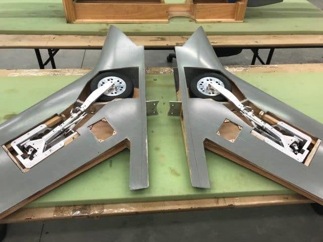
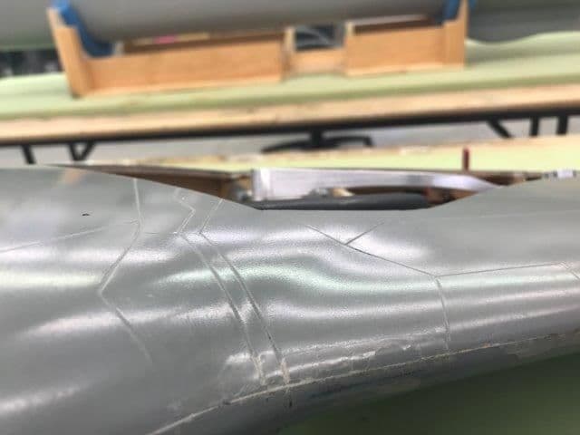
Gear folds into wells with very little clearance around tires. Will have to see how it works with doors.
Next stop...gear doors, which IMO are the worst thing about RC jets. I don't like them, try to avoid them if possible, but on this jet they are necessary. How to do them is TBD but I have some good photos from Phil Clark at Fighteraces in the UK.
This ends work this week. The shop is being taken over for the granddaughters 9th birthday party. 15 kids are going to have a craft painting party and games. I'll try to hide RC stuff in the camper as much as possible. This will be a challenging weekend!
First I replaced 2 hex head bolts with counter sunk flat head bolts to make more clearance for the tire in gear well
Drilled left wing mounts and laminated the 3/32" ply spacers on to rails
Drilled right wing mounts for 6-32 bolts
I could not get the blind nuts into the maple beam mounts and I did not want to drill an oversize hole in the mounts so I sunk the blind nuts into 1/8" ply squares
Blind nuts epoxied to bottom of gear mount rails. I use vaseline on bolt threads to keep epoxy from locking bolts in.
Aluminum gear mounts countersunk and gear installed with flat head bolts to give clearance for gear door cover.
Same of left side
Main gear mounted
Gear folds into wells with very little clearance around tires. Will have to see how it works with doors.
Next stop...gear doors, which IMO are the worst thing about RC jets. I don't like them, try to avoid them if possible, but on this jet they are necessary. How to do them is TBD but I have some good photos from Phil Clark at Fighteraces in the UK.
This ends work this week. The shop is being taken over for the granddaughters 9th birthday party. 15 kids are going to have a craft painting party and games. I'll try to hide RC stuff in the camper as much as possible. This will be a challenging weekend!
Last edited by Viper1GJ; 12-14-2018 at 02:13 PM.
12-14-2018, 02:06 AM
#197
I think the problem with any kind of glued in stud or threaded rod is the inset wing root pocket in the fuse. The last 3/4" of travel when the wing is inserted is inside the pocket does not allow any fore or aft movement to get the spar tab over a fixed bolt stud. The way Bob has it designed is the wing has to slide into the inset pocket and the spar tab slides on the back side of the wing former in contact with it. This is why you have to put the bolt in after the wing is fully inserted into the fuse pocket.
12-14-2018, 06:01 AM
#198

So, if I get you right, until the wing is fully inserted, the hole in the wing and the hole in the fuselage do not fully line up longitudinally? Can't tell from the pictures. The plane where I used this technique also has a wing pocket, but the pocket is parallel to the roll axis and the rod parallel to the wing spar, so it lines up perfectly and goes into the hole, then the bolt inside the fuse takes it from there
i think your stuck on the bolt by the turbine.
There is also a blade style spar far forward of the turbine that has bolts that go in longitudinally through that spar and a fuselage bulkhead. Then there is the bolt by the turbine that goes in laterally as well.
Using a �stud� in the bolt position by the turbine would work, but up towards the blade spar wont bc of the �pocket� the wing goes into.
12-14-2018, 02:19 PM
#199
Thread Starter
My Feedback: (20)
So, if I get you right, until the wing is fully inserted, the hole in the wing and the hole in the fuselage do not fully line up longitudinally? Can't tell from the pictures. The plane where I used this technique also has a wing pocket, but the pocket is parallel to the roll axis and the rod parallel to the wing spar, so it lines up perfectly and goes into the hole, then the bolt inside the fuse takes it from there
Thomas, you are correct.
Gary
Last edited by Viper1GJ; 12-14-2018 at 02:21 PM.
12-14-2018, 02:36 PM
#200

Gary,
With the stud in the wing root method, could you not have a slot in the fuselage to allow the relative movement of the stud as you insert the wing. A large washer or plate underneath the nut would ensure sufficient clamping area and cover up the slot.
Paul
With the stud in the wing root method, could you not have a slot in the fuselage to allow the relative movement of the stud as you insert the wing. A large washer or plate underneath the nut would ensure sufficient clamping area and cover up the slot.
Paul