


1/6 F-105 Build Thread
 11-06-2018, 06:32 PM
#151

Thread Starter
My Feedback: (20)
Pull Up, there is about 2.25" on each side for the stab bearing blocks.
I went back with more time to do a repeatable shim test to make sure the turbine and pipe are straight and level with the fuse.
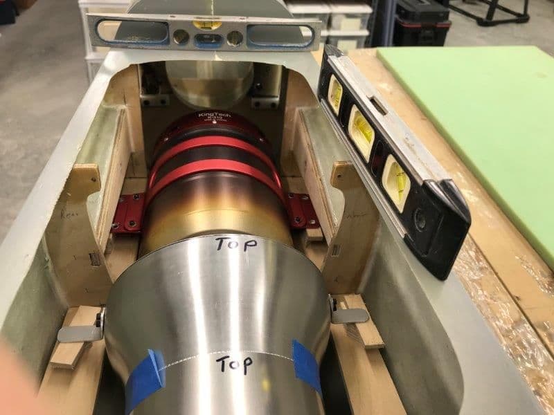
This time I used a 3/4" shim under the turbine and pipe. The fuse was leveled in pitch and roll.
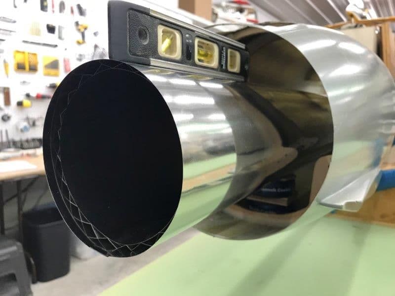
I ensured the fuse was level and the pipe was level and centered in the nozzle exit hole.
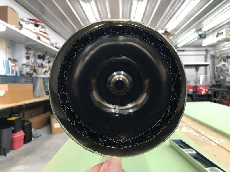
Pipe centered in nozzle exit hole.
Now it looks right from the side. I will go ahead and cut some longer 3/4" plywood shims to mount the turbine and pipe on.
I went back with more time to do a repeatable shim test to make sure the turbine and pipe are straight and level with the fuse.
This time I used a 3/4" shim under the turbine and pipe. The fuse was leveled in pitch and roll.
I ensured the fuse was level and the pipe was level and centered in the nozzle exit hole.
Pipe centered in nozzle exit hole.
Now it looks right from the side. I will go ahead and cut some longer 3/4" plywood shims to mount the turbine and pipe on.
 11-06-2018, 06:45 PM
#152
Thread Starter
My Feedback: (20)
I added an inside edge to the nose gear well for the nose gear doors to rest on when closed.
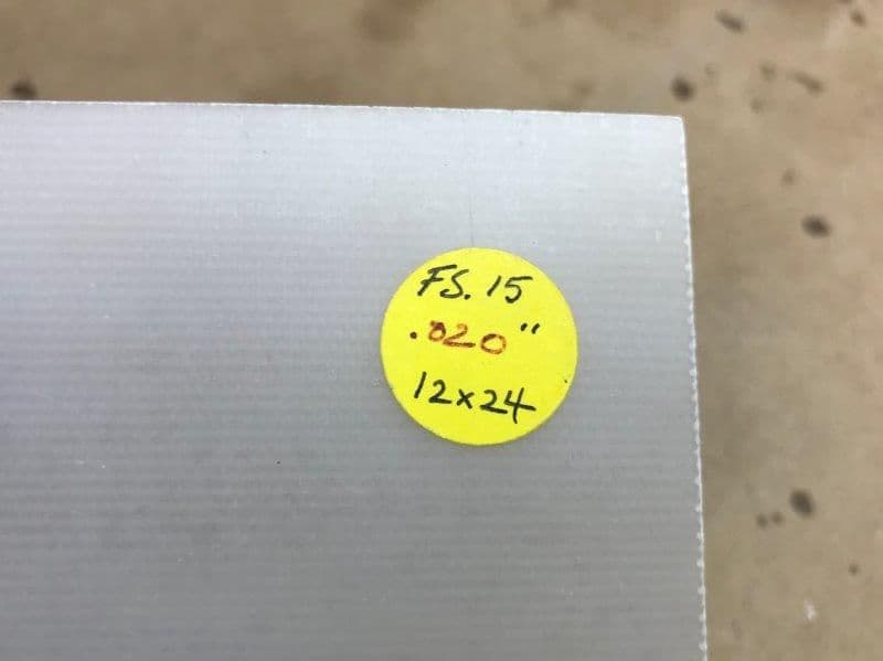
I used .020 G10 sheet
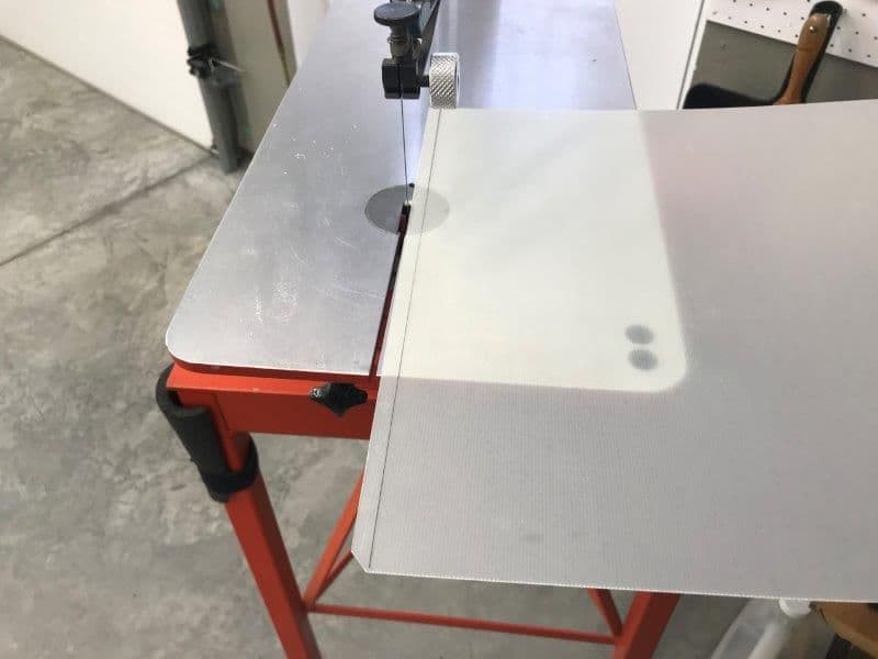
G10 was cut into strips
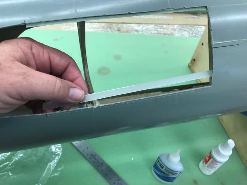
G10 strips were added to the inside of the nose gear door opening
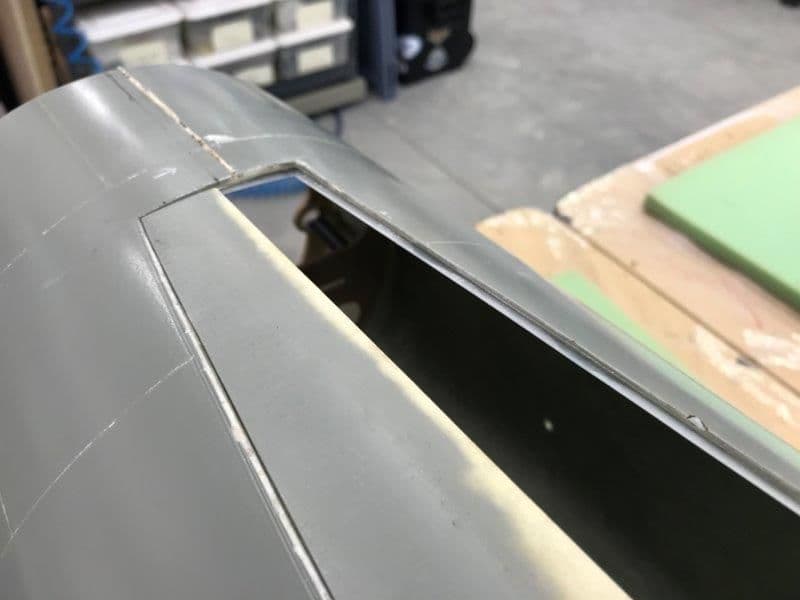
Results were good for resting the nose gear doors on when closed

Now for hinging
I used .020 G10 sheet
G10 was cut into strips
G10 strips were added to the inside of the nose gear door opening
Results were good for resting the nose gear doors on when closed
Now for hinging
11-06-2018, 07:01 PM
#153
Thread Starter
My Feedback: (20)
Dry fit of nose gear and gear door hinges to check for gear and hinge clearance.
Mock up of extra large offset door hinge from enlarged drawing of 3D printed hinges from Ultimate Jets.

Double sided mounting tape use to place hinges in fuse for testing
Wire use to keep hinge pivots in line
Blind nuts installed in nose gear mounts
Nose gear mounted to test for clearance of door hinges
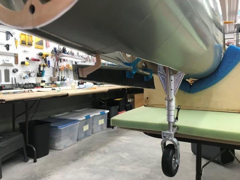
Gear strut clears hinges when extended
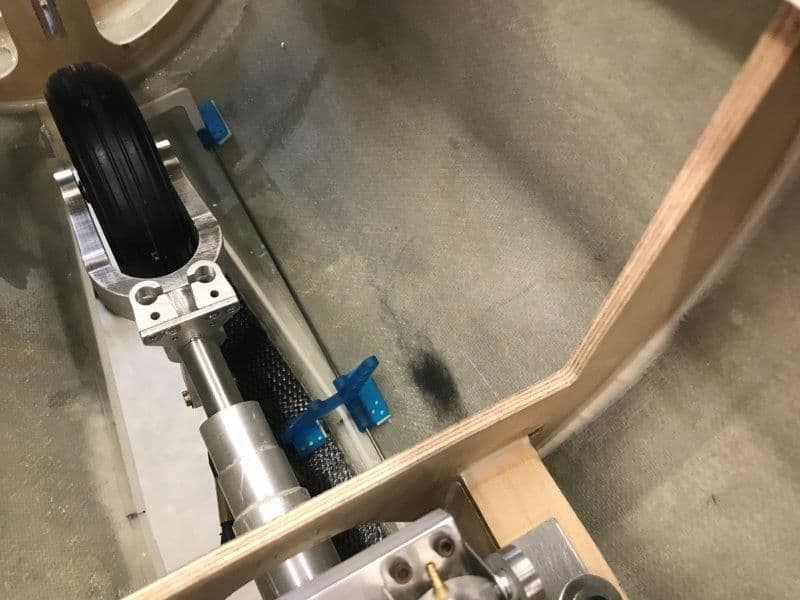
I had to move the large hinge forward to clear the tire when retracted.
Mock up of extra large offset door hinge from enlarged drawing of 3D printed hinges from Ultimate Jets.
Double sided mounting tape use to place hinges in fuse for testing
Wire use to keep hinge pivots in line
Blind nuts installed in nose gear mounts
Nose gear mounted to test for clearance of door hinges
Gear strut clears hinges when extended
I had to move the large hinge forward to clear the tire when retracted.
11-07-2018, 11:29 AM
#154

holy crap those hinges are awesome, I do the hinge pin in the same manner. I am having a hard time sourcing the normal black plastic offset hinges, Yellows and Tams were nice but it appears a lot of people are copying and the material used now is very poor.
11-07-2018, 02:20 PM
#155
My Feedback: (3)

Join Date: Oct 2005
Location: san jose,
CA
Posts: 880
Likes: 0
Received 0 Likes
on
0 Posts
Great thread. I saw one of Bob's F-105s fly(with Ali as pilot) at BITW several years back. It's probably the one you refer to at the beginning of the thread.
Quite a sight to see since I saw the full size fly with the Kansas ANG back in the day.
Gary, did you extend the wing spar or change it? .. couldn't tell from one of the later pics.
Quite a sight to see since I saw the full size fly with the Kansas ANG back in the day.
Gary, did you extend the wing spar or change it? .. couldn't tell from one of the later pics.
11-07-2018, 03:18 PM
#156
Thread Starter
My Feedback: (20)
Hi Matt,
The door hinges are from Ultimate Jets. I really like them. Its a great design. They are 3D printed.
Here is the link: https://www.ultimate-jets.net/produc...-offset-hinges
The large hinge is a mockup of an enlarged hinge that is a special order from Ultimate Jets. The full size mockup was to test the size and fit before hinges were 3D printed. Oli has been very good helping me with things like this in the past. Many thanks Oli.
Gary
11-07-2018, 03:31 PM
#157
Thread Starter
My Feedback: (20)
dbsonic,
Thanks for the compliment on the thread. I guess I enjoy posting stuff as much as working on it.
However, your question above got my attention...what do you know about the wing spar that I don't? Is there something I need to know about extending or changing the wing spar?
The aluminum plate spar and the plywood wing spar former are the foundation of the whole airplane. Its like the foundation of a house. Everything else is built on it. Its not the design I would make but I guess all three of the F-105s I know that have flown used it. It would be very difficult to change. I'm still thinking about a way to beef up the main spar former.
With the known gear retraction, toe in, mounting, and stab design issues, I'm hoping there is not something else.
Gary
Last edited by Viper1GJ; 11-07-2018 at 03:39 PM.
11-07-2018, 04:21 PM
#158
My Feedback: (3)
Join Date: Oct 2005
Location: san jose,
CA
Posts: 880
Likes: 0
Received 0 Likes
on
0 Posts
No, none that I am aware of. Looking back at the pics, appears same.
But agree reinforcement is not a bad idea. Like carbon laminate on the ply former the spar attaches to.
I remember Ali flew it really scale like. Not aggressive. Nice landings too.
Darren
But agree reinforcement is not a bad idea. Like carbon laminate on the ply former the spar attaches to.
I remember Ali flew it really scale like. Not aggressive. Nice landings too.
Darren
11-07-2018, 04:35 PM
#159
Thread Starter
My Feedback: (20)
Yes, similar to the idea I was thinking about.
I was thinking about laminating the front of the former with CF cloth. Then cutting a 1/4" ply doughnut ring and laminating both sides with CF cloth. The hole would be the same size as the air intake hole in the wing former. Then taking that ring and laminating it to the forward side of the wing former. Then re-drill the wing bolt holes through the extra ply and CF beef on the front side. You cant put anything on the back side of the former because of the close fit of the aluminum spar blades and the aft face of the former. I think the weak spot then would be the bolt holes in the 1/8" aluminum spar blade but not much I can do about that.
Thanks for the help, Gary
11-07-2018, 06:21 PM
#160
Thread Starter
My Feedback: (20)
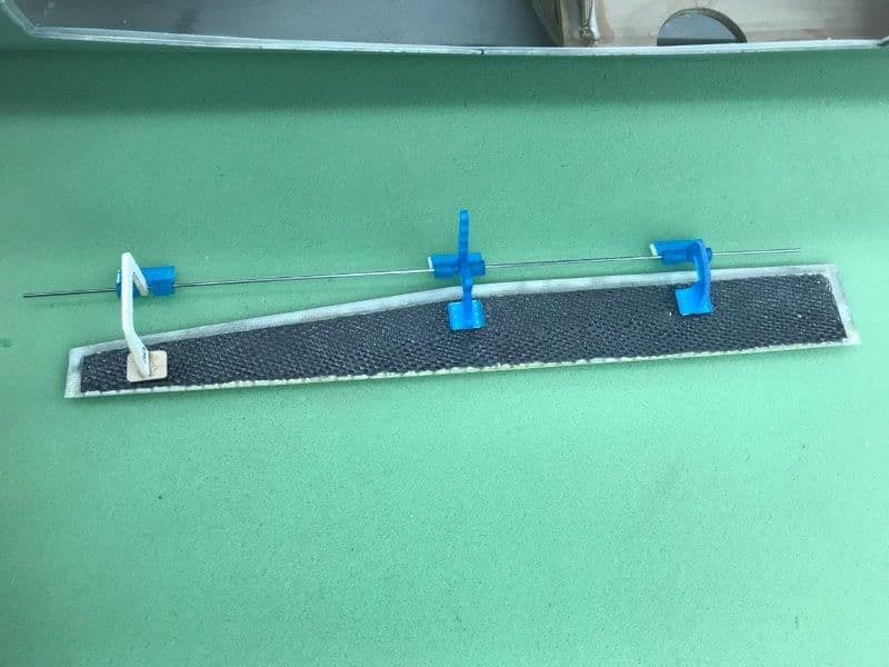
Began installing servos in servo wells. There are 5, all done the same way.
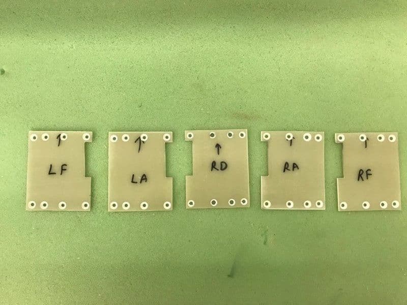
1/16" G10 servo well covers all cut, drilled, and countersunk.
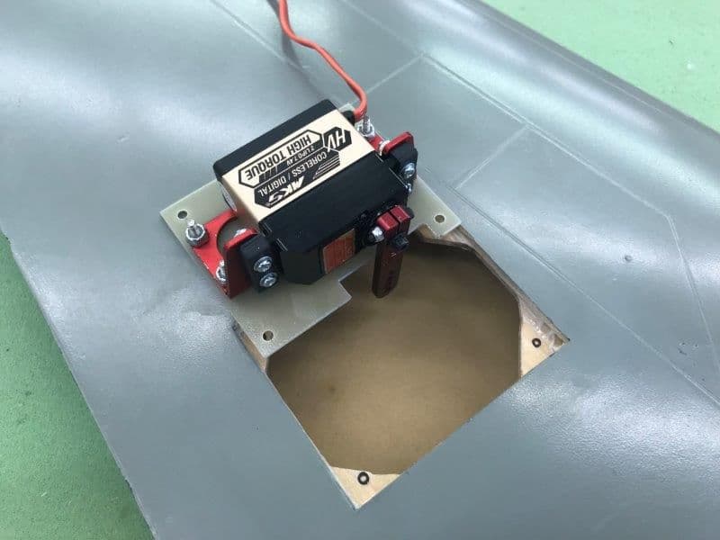
Servos mounted to brackets, servo arms attached, and brackets mounted to G10 covers.
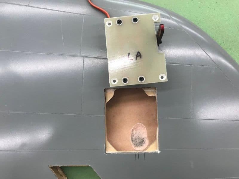
Parts of plywood mounts and airex material on inside of top skin removed as necessary to get clearance for servo and bracket.
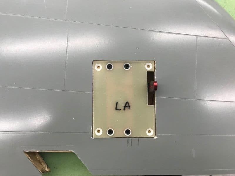
Once the servo cover was dropped in servo the well it was not flush with skin surface so it had to be shimmed on each corner.
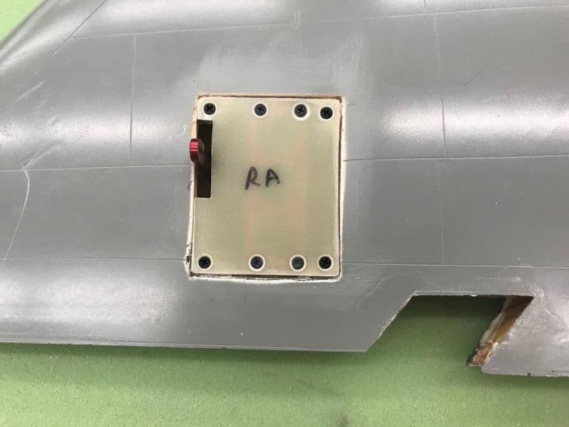
After proper shim level achieved, shims were glued in, holes marked, drilled, blind nuts installed, edges sanded, and 4-40 flat head bolts installed. Right aileron servo completed.
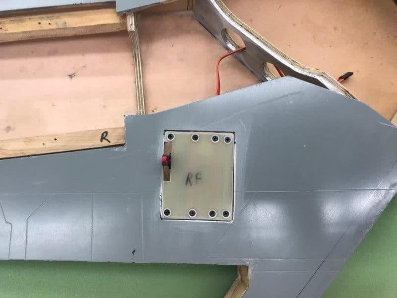
Right flap servo completed
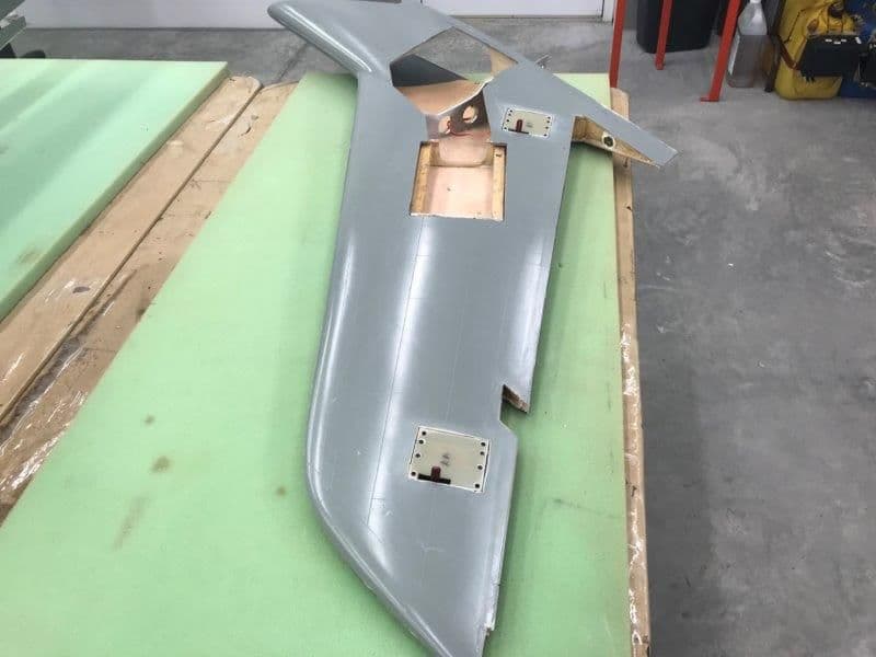
RIght wing done, left wing to go.
Low angle view.
1/16" G10 servo well covers all cut, drilled, and countersunk.
Servos mounted to brackets, servo arms attached, and brackets mounted to G10 covers.
Parts of plywood mounts and airex material on inside of top skin removed as necessary to get clearance for servo and bracket.
Once the servo cover was dropped in servo the well it was not flush with skin surface so it had to be shimmed on each corner.
After proper shim level achieved, shims were glued in, holes marked, drilled, blind nuts installed, edges sanded, and 4-40 flat head bolts installed. Right aileron servo completed.
Right flap servo completed
RIght wing done, left wing to go.
Low angle view.
11-07-2018, 06:50 PM
#161
Thread Starter
My Feedback: (20)
While I've been cutting and hacking in the shop a good friend, Keith Alexander, who is real good with the 3D printing stuff, offered to help with 3D printing of the engine bay airscoops and speedbrake hinges. The speedbrake hinges on the full scale hinge the 4 pedal speedbrake shell that also functions as an afterburner nozzle. They are quite distinctive and add character to the jet. The speedbrake 3D print file was developed by Bob Rullie and he emailed it to me.
The engine bay air scoops were added on later model F105s to help stop engine overheats and fires. They are on all F-105Ds which is what I am modeling.
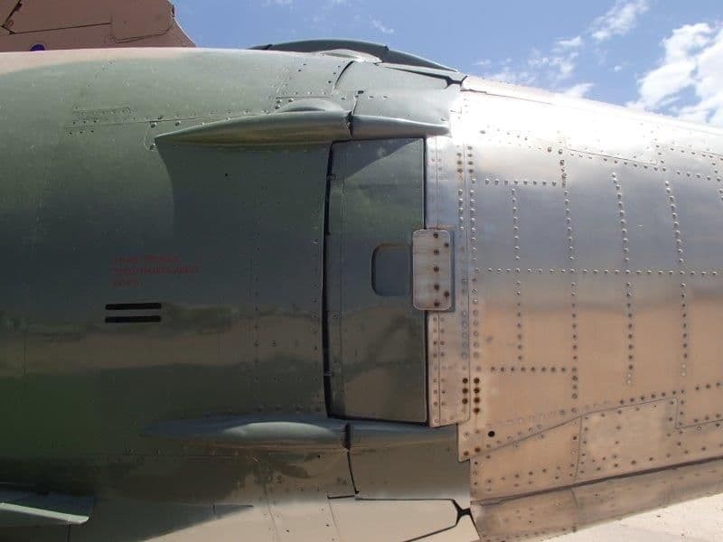
Speedbrake hinge tear drop shaped covers on full scale jet. There are 8 total.
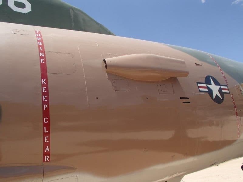
Engine bay air scoop on full scale. There is one on each side. I gave Keith this photo and several others, some known dimensions from the model, and we were able to determine the scale size of the scoop for the model. Then he developed the CAD model and 3D print file based on the photos.
Speedbrake hinge 3D printout.
Engine bay air scoop 3D print out.

Full set ready to go. We will print two sets, one for me and one for Larry Sorenson plus some spares. Thanks Keith for all your help.
Gary
The engine bay air scoops were added on later model F105s to help stop engine overheats and fires. They are on all F-105Ds which is what I am modeling.
Speedbrake hinge tear drop shaped covers on full scale jet. There are 8 total.
Engine bay air scoop on full scale. There is one on each side. I gave Keith this photo and several others, some known dimensions from the model, and we were able to determine the scale size of the scoop for the model. Then he developed the CAD model and 3D print file based on the photos.
Speedbrake hinge 3D printout.
Engine bay air scoop 3D print out.
Full set ready to go. We will print two sets, one for me and one for Larry Sorenson plus some spares. Thanks Keith for all your help.
Gary

 11-08-2018, 06:10 PM
#163
Thread Starter
My Feedback: (20)
Lol Paul, you must think I can do CAD, 3D printing, and laser cutting!
Well, actually I did consider it at first but complexity, incorrect aft shape of the fuse nozzle, extra tail weight, and mostly the other problems I found with the parts, I quickly gave up on it. The fake hinges will have to do.
Gary
Well, actually I did consider it at first but complexity, incorrect aft shape of the fuse nozzle, extra tail weight, and mostly the other problems I found with the parts, I quickly gave up on it. The fake hinges will have to do.
Gary

 11-12-2018, 07:41 PM
#165
Thread Starter
My Feedback: (20)
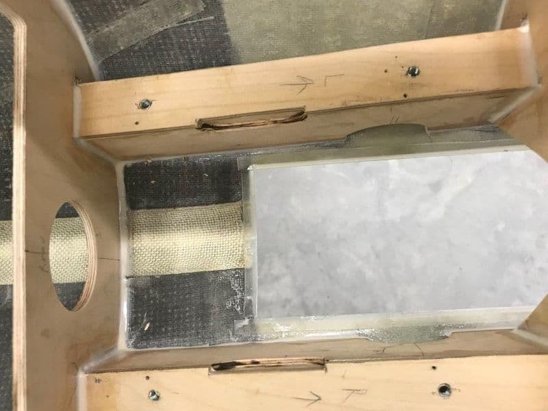
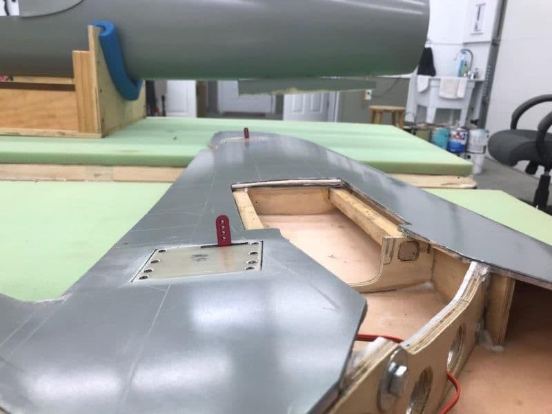
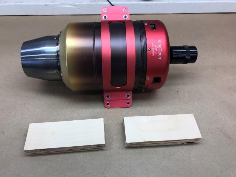
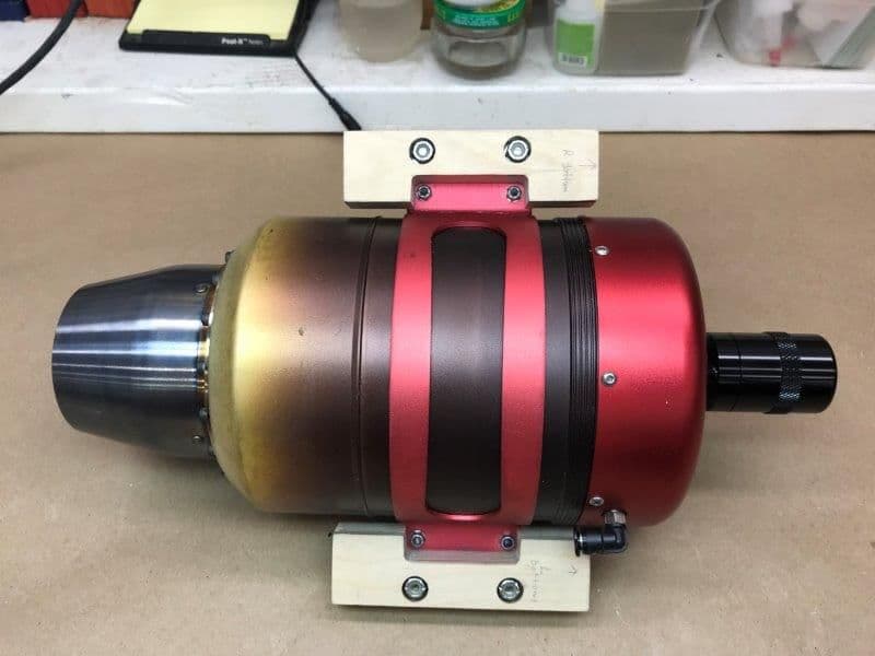
I started trying to get the K-310 turbine in the mounts. I quickly found out it is really tight even though my pink foam template showed a good fit. The F-105 coke bottle fuse shape is most narrow at the turbine mounting location, which makes the tight fit worse.
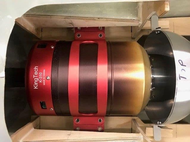
The K-310 has a wide can size and large mounting bracket. I did not realize the bracket extended so far under the wing inset pocket. That makes it is very hard to get the holes drilled, a bolt in, and a tool to turn the bolt. The is not much room between the can and the wood rails for heat resistance on the wood rails so I considered shaving off some of the inside rail. Then I looked at using the bracket bolts for mounting to the rails but there is not much wood meat there after shaving a little more clearance for heat. Also to center the turbine on the fuse centerline it has to be slightly offset to the right on the rails since I found the entire fuse to be slightly offset at the turbine mount area.
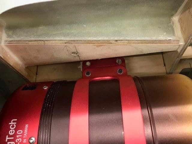
The photo does not show well the distance the mounting holes are under the wing pocket. Its really under there and not much clearance to get a bolt in.
After all this for a day I got frustrated with it and put it in the penalty box for a while. I have some radio installs and upgrades to do on other jets so I'll do that and think about what to do here. Maybe a smaller turbine would be best, but I like the thrust available if you need it. Plus I got the K-310 in a no cash trade so no funds spent on it. Arrrggghhh!
Gary
The K-310 has a wide can size and large mounting bracket. I did not realize the bracket extended so far under the wing inset pocket. That makes it is very hard to get the holes drilled, a bolt in, and a tool to turn the bolt. The is not much room between the can and the wood rails for heat resistance on the wood rails so I considered shaving off some of the inside rail. Then I looked at using the bracket bolts for mounting to the rails but there is not much wood meat there after shaving a little more clearance for heat. Also to center the turbine on the fuse centerline it has to be slightly offset to the right on the rails since I found the entire fuse to be slightly offset at the turbine mount area.
The photo does not show well the distance the mounting holes are under the wing pocket. Its really under there and not much clearance to get a bolt in.
After all this for a day I got frustrated with it and put it in the penalty box for a while. I have some radio installs and upgrades to do on other jets so I'll do that and think about what to do here. Maybe a smaller turbine would be best, but I like the thrust available if you need it. Plus I got the K-310 in a no cash trade so no funds spent on it. Arrrggghhh!
Gary
Last edited by Viper1GJ; 11-12-2018 at 07:43 PM.
11-13-2018, 04:58 AM
#166

Get a couple of mounting tabs from BVM and discard the engine mount. You can use the provided hoops that come with the mounting tabs or a pair of extra large hose clamps, Unless there is a specific need for the kingtech mount.
You're doing great. Keep up the good work.
You're doing great. Keep up the good work.
11-13-2018, 07:23 AM
#167
You could just use the inside holes of the hoop also? Either w/ blind nuts or self-tapping screws. I have never had a problem w/ self-tapping screws since they is no vibration.
Seems like an easy fix.....
Seems like an easy fix.....
Last edited by jetjon; 11-13-2018 at 07:26 AM.
11-13-2018, 05:15 PM
#168
Thread Starter
My Feedback: (20)
Yes the inside holes of the bracket were my first idea. Probably will work ok. I got several ideas sent today, angled bolts with threaded inserts on bottom, bolting the turbine to the 3/4" risers and then bolting the risers to the rails, and others. The F=105 been on the back table for a week now and it seems workable now. I just got frustrated that my plan did not work at first so taking a break has produced several solutions. That's what's so good about this forum. There are so many smart folks here that provide great ideas.
I just installed a satellite receiver and a CTU in my Sabre XLT. Its ready for testing. Now installing the Jeti radio system and CTU in my Avanit XXL. When I get this finished I'll get back to the F-105 with a fresh outlook and press on.
Thanks to all for the ideas and encouragement.
Gary
I just installed a satellite receiver and a CTU in my Sabre XLT. Its ready for testing. Now installing the Jeti radio system and CTU in my Avanit XXL. When I get this finished I'll get back to the F-105 with a fresh outlook and press on.
Thanks to all for the ideas and encouragement.
Gary
11-25-2018, 06:38 PM
#170
Thread Starter
My Feedback: (20)
I finally got back to the F-105 this weekend. I took a couple of weeks to update and install the Jeti radio and CTU in my Sabre XLT and Avanti XXL. I'm very impressed with the CTU on the install, programming, and test runs but have not had a chance to fly it yet.
I made progress on several issues with lots of help during the work break plus I figured out the turbine mount from a suggestion from Jamie Snipes. I do my best CAD (Come Along Design) work while walking around daydreaming, so a couple of weeks didn't hurt.
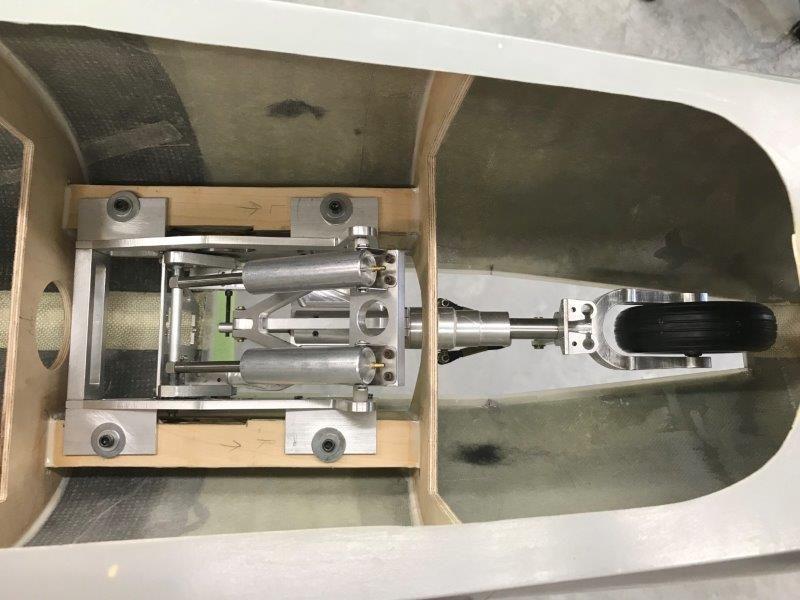
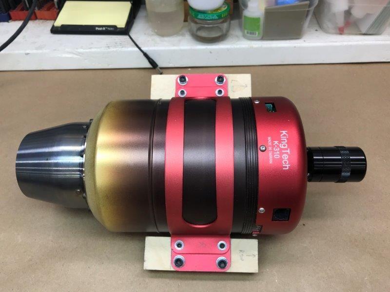
The turbine needed to be raised 3/4" for alignment so I made blocks from plywood to make the risers.
Layers of aircraft ply laminated with epoxy to make 3/4" thick blocks
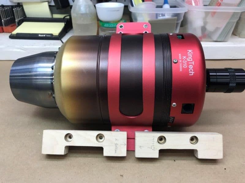
Blocks trimmed to size, cut out, drilled and counter sunk for bolts and nylon lock nuts.
Top view
Bottom view with nylon lock nuts counter sunk flush with bottom surface

Turbine dry fit in position, holes will be drilled through the blocks into the mounting rails to fasten turbine in place after the rails are glued in and alignment determined.
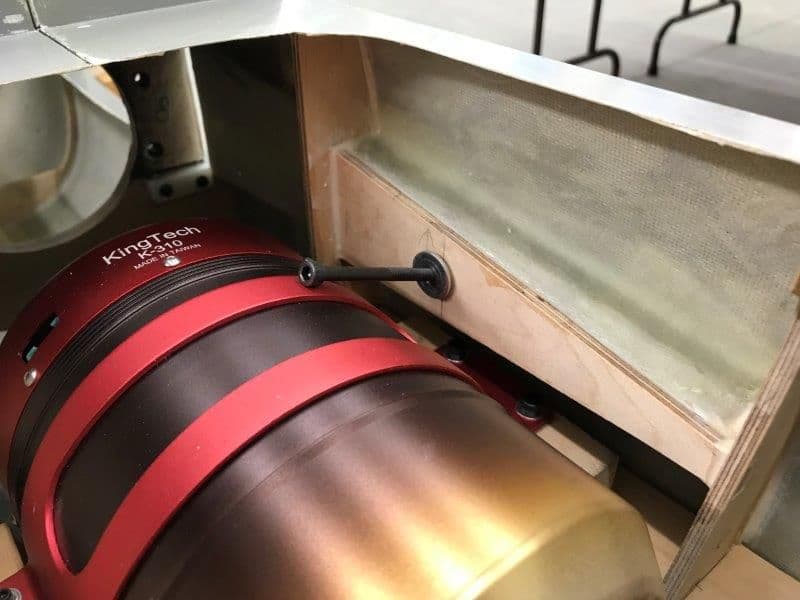
Raising the turbine made it more difficult to insert the wing trailing edge mounting bolt. I will have to drill the hole offset to insert the bolt and then level it to fasten the trailing edge of the wing to the fuse. The bolt only provides tension holding so the offset hole will not matter.
I made progress on several issues with lots of help during the work break plus I figured out the turbine mount from a suggestion from Jamie Snipes. I do my best CAD (Come Along Design) work while walking around daydreaming, so a couple of weeks didn't hurt.
The turbine needed to be raised 3/4" for alignment so I made blocks from plywood to make the risers.
Layers of aircraft ply laminated with epoxy to make 3/4" thick blocks
Blocks trimmed to size, cut out, drilled and counter sunk for bolts and nylon lock nuts.
Top view
Bottom view with nylon lock nuts counter sunk flush with bottom surface
Turbine dry fit in position, holes will be drilled through the blocks into the mounting rails to fasten turbine in place after the rails are glued in and alignment determined.
Raising the turbine made it more difficult to insert the wing trailing edge mounting bolt. I will have to drill the hole offset to insert the bolt and then level it to fasten the trailing edge of the wing to the fuse. The bolt only provides tension holding so the offset hole will not matter.
11-25-2018, 06:47 PM
#171
Thread Starter
My Feedback: (20)
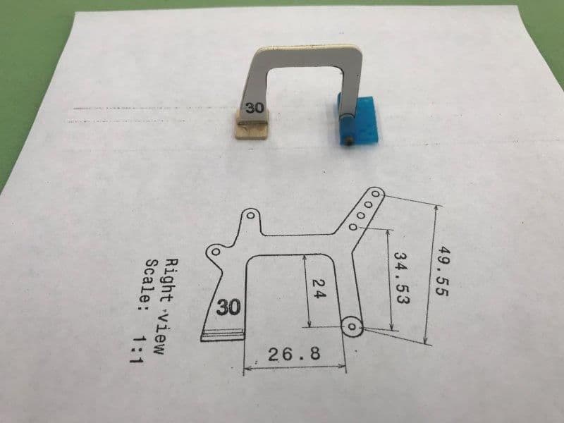
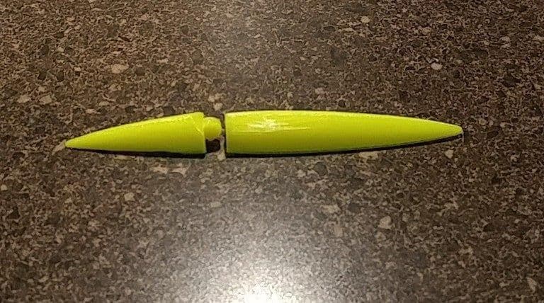
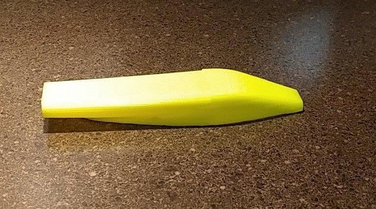
During the work break I received the large offset nose gear door hinges. These hinges were 3D printed by Oli at Ultimate Jets on special order. He did a great job and the hinges look like they will work great on the large gap due to the gear door taper.

11-25-2018, 07:21 PM
#172
Thread Starter
My Feedback: (20)
My friend Keith Alexander has been helping me with 3D printing the engine bay airs coops and speed brake hinge fairings. He gave me his first cuts at the shapes and they look real good. He is going to tweak the air scoops a little but over all they will really add some scale character to the jet. These parts would be a real pain to carve from wood. Many thanks Keith.
Gary

Gary