


1/6 F-105 Build Thread
 09-02-2021, 04:58 PM
#926

Thread Starter
My Feedback: (20)
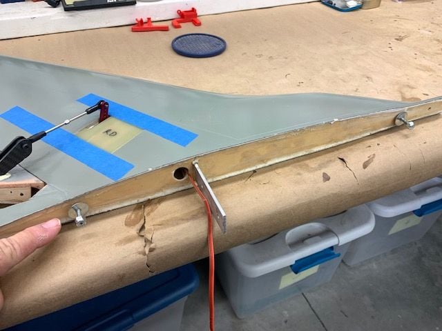
Wings Finished!
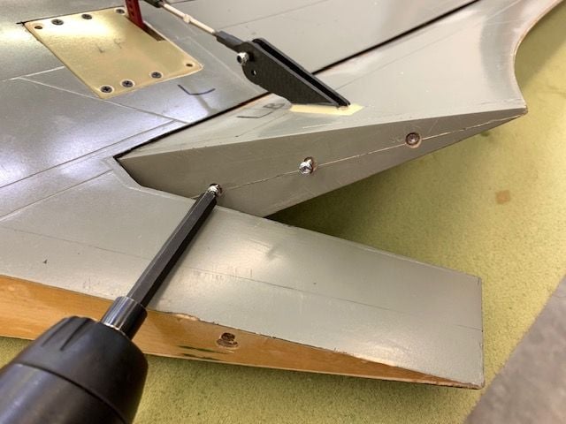
Flap end caps installed
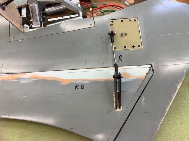
Pushrod ball links secured with washers and lock nuts on both ends.
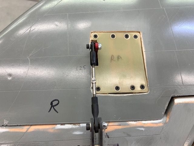
Servo hatches removed and servo plugs safety tied. Servo hatches re-installed with all screws.
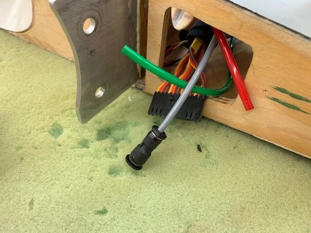
Reducing connector installed on brake line to connect to 4mm lines in fuse
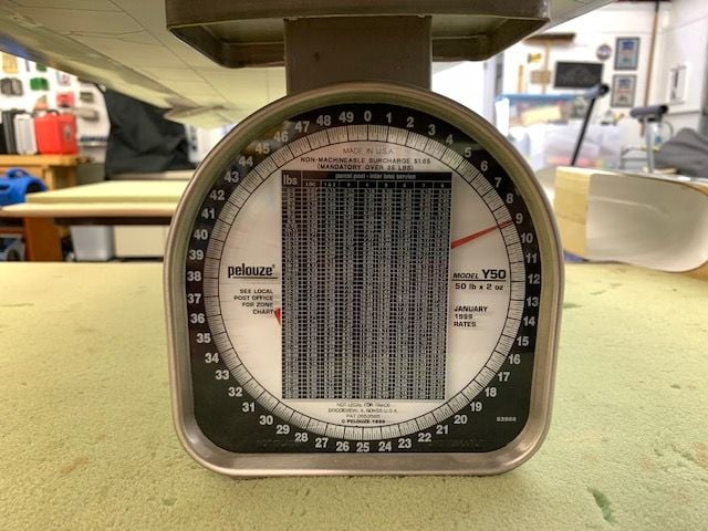
I weighed each wing and both were 9 lbs. Heavy but normal for this jet. At least they are the same!
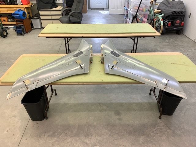
I here by declare these wings finished. They are ready for mounting, CG checks, and final testing on the fuse.
Canopy, cockpit, and vertical fin to go...
Flap end caps installed
Pushrod ball links secured with washers and lock nuts on both ends.
Servo hatches removed and servo plugs safety tied. Servo hatches re-installed with all screws.
Reducing connector installed on brake line to connect to 4mm lines in fuse
I weighed each wing and both were 9 lbs. Heavy but normal for this jet. At least they are the same!
I here by declare these wings finished. They are ready for mounting, CG checks, and final testing on the fuse.
Canopy, cockpit, and vertical fin to go...
Last edited by Viper1GJ; 09-02-2021 at 05:04 PM.

The following 8 users liked this post by Viper1GJ:
Auburn02 (09-02-2021),
camss69 (09-02-2021),
cetigershark (09-05-2021),
f106jax (09-03-2021),
grbaker (09-02-2021),
and 3 others liked this post.
09-04-2021, 05:38 PM
#927
Thread Starter
My Feedback: (20)
Cockpit tub
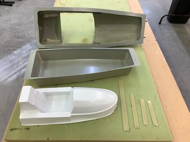
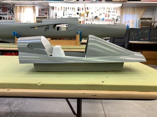
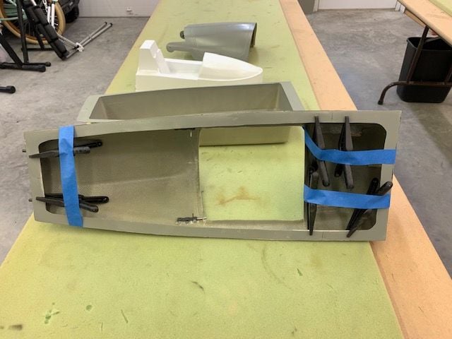
These are the cockpit parts I have. The top two, the canopy hatch and tub came with the 105 parts. The white one is a cockpit from an old Eurosport repair from around 2005. I plan to use it for a temporary cockpit. I used the wet tile saw to cut the 1/16" G-10 strips for the install.
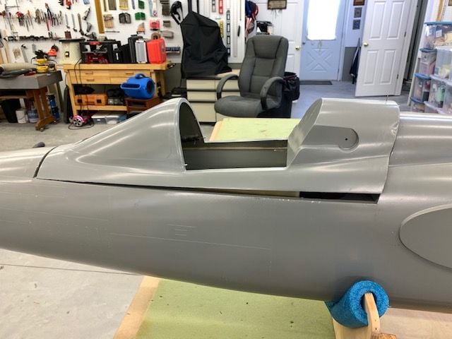
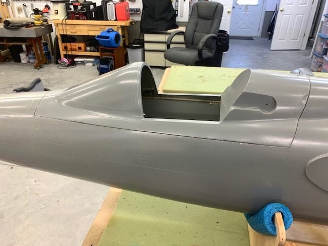
My plan is to install the tub to the bottom of the canopy hatch and put in the Eurosport cockpit in with some Velcro as a temporary cockpit like the mockup here.
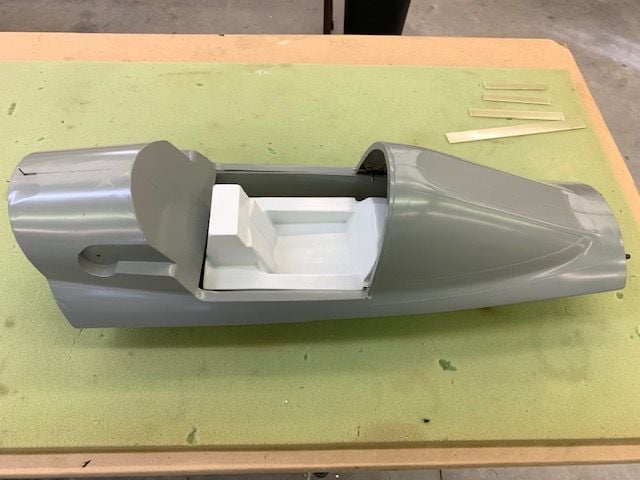
Side view. The canopy hatch has to sit flush on the fuse so screws or mounting tabs can not be in the joint line.
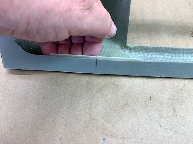
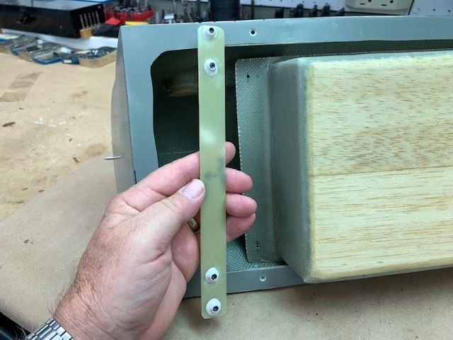
The bottom edges of the canopy hatch are too thin and not strong enough to hold screws. My plan is to epoxy 1/16" G-10 strips inside the base of the hatch to allow a flat head 4-40 screw to be counter sunk into the G-10. The screws will then attach the tub to the inside of the hatch. That's the plan anyway...
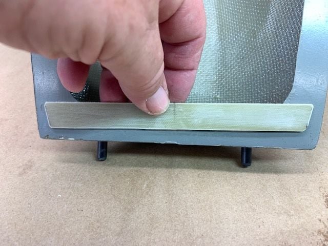
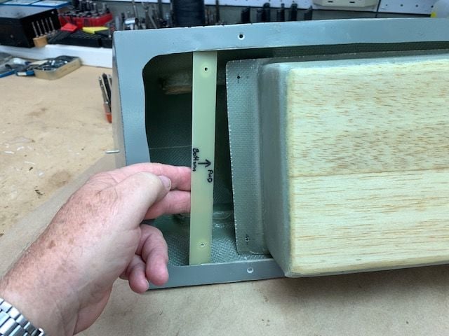
G-10 strip dry fit inside the front of the canopy hatch
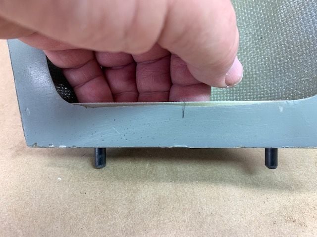
A strip of G-10 on each side of the canopy hatch positioned at the rear of the tub to stiffen the side and allow the countersunk screws.
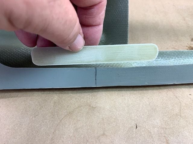
Side strip dry fit on the canopy hatch rail
Three strips epoxied inside the canopy hatch and held in with pinch clamps. I taped the clamps to keep them from flopping around during work.
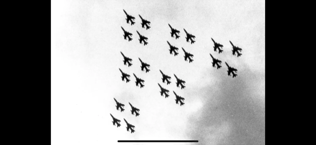
I found this photo today of the Thud retirement flyover at Hill AFB on 4 JUN 1883. I had just left Hill AFB for Kunsan AB in Korea a few months before.
Cool formation.
These are the cockpit parts I have. The top two, the canopy hatch and tub came with the 105 parts. The white one is a cockpit from an old Eurosport repair from around 2005. I plan to use it for a temporary cockpit. I used the wet tile saw to cut the 1/16" G-10 strips for the install.
My plan is to install the tub to the bottom of the canopy hatch and put in the Eurosport cockpit in with some Velcro as a temporary cockpit like the mockup here.
Side view. The canopy hatch has to sit flush on the fuse so screws or mounting tabs can not be in the joint line.
The bottom edges of the canopy hatch are too thin and not strong enough to hold screws. My plan is to epoxy 1/16" G-10 strips inside the base of the hatch to allow a flat head 4-40 screw to be counter sunk into the G-10. The screws will then attach the tub to the inside of the hatch. That's the plan anyway...
G-10 strip dry fit inside the front of the canopy hatch
A strip of G-10 on each side of the canopy hatch positioned at the rear of the tub to stiffen the side and allow the countersunk screws.
Side strip dry fit on the canopy hatch rail
Three strips epoxied inside the canopy hatch and held in with pinch clamps. I taped the clamps to keep them from flopping around during work.
I found this photo today of the Thud retirement flyover at Hill AFB on 4 JUN 1883. I had just left Hill AFB for Kunsan AB in Korea a few months before.
Cool formation.
Last edited by Viper1GJ; 09-04-2021 at 05:44 PM.
09-05-2021, 04:45 PM
#928
Thread Starter
My Feedback: (20)
Cockpit tub install
I changed the plan for the cockpit tub to have screws only on the aft end. The front end will have the tub front lip in a slot with out any screws. First I squared up the tub front lip to fit inside the cockpit hatch.
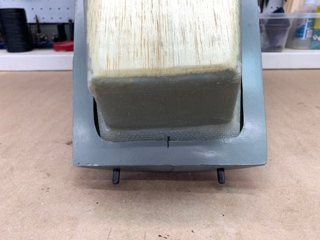
Tub taped in center of cockpit hatch and center marked
Plastic taped over the front lip to keep epoxy from sticking to tub
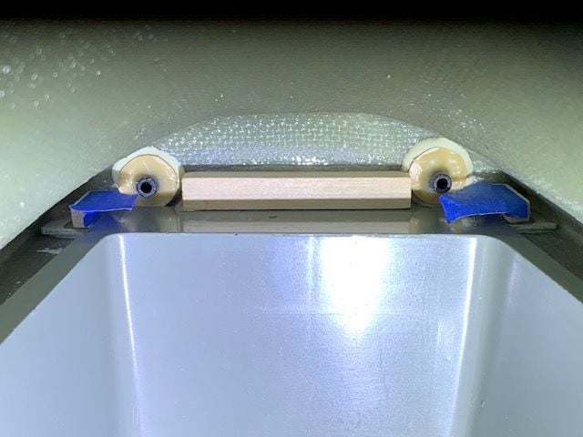
A 3/8" x 3/8" square piece of poplar epoxied to front of canopy hatch to make a slot. I used blue tape to make a removeable handle to put the block in place with long forceps
Block glued in place and tape removed forming a slot underneath the block
1/4" x 1/4" poplar blocks glued on left and right sides of cockpit tub lip to keep it centered in the slot
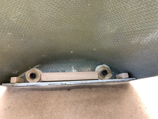
All the blocks glued in the front of the canopy hatch
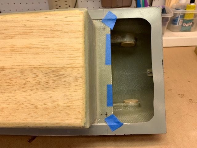
After the front of the tub was in place I taped the aft strip of 1/16" G-10 under the aft lip of the tub. Then drill hole locations were marked.
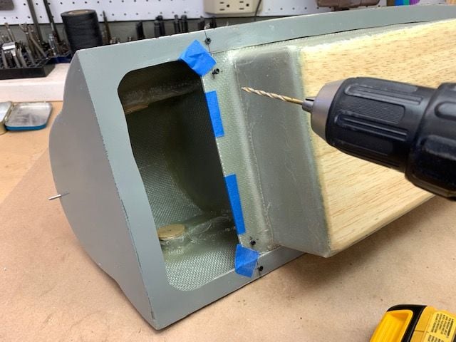
Holes drilled for 4/40 bolts. Bolts inserted after each hole drilled to help hold the G-10 strip in place during the next drilling.
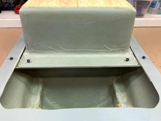
Holes drilled and tape removed
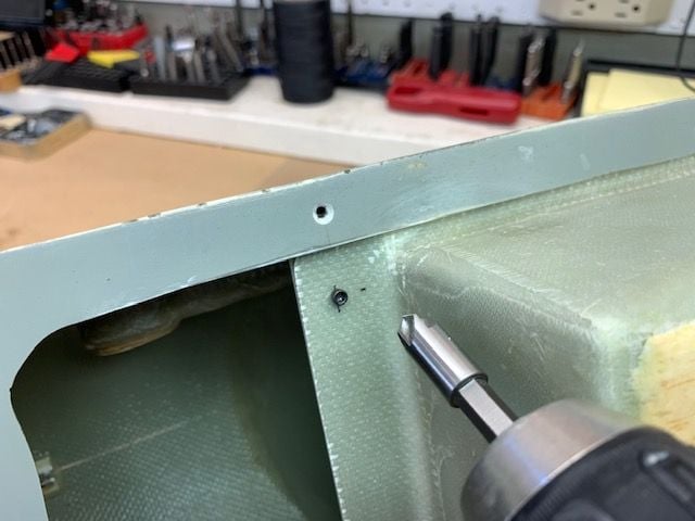
Outside holes were counter sunk for the 4-40 flat head screws that hold the strip and tub to the cockpit hatch
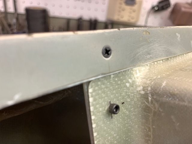
Counter sunk bolt head flush with cockpit tub surface
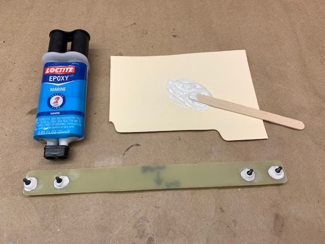
4-40 nylon lock nuts epoxied to the G-10 strip with Locktite Marine epoxy. I got it at Lowes a couple of years ago and am trying to use it up on small stuff. Seems to work just like Hysol 9462 but I don't have any specs on it.
I changed the plan for the cockpit tub to have screws only on the aft end. The front end will have the tub front lip in a slot with out any screws. First I squared up the tub front lip to fit inside the cockpit hatch.
Tub taped in center of cockpit hatch and center marked
Plastic taped over the front lip to keep epoxy from sticking to tub
A 3/8" x 3/8" square piece of poplar epoxied to front of canopy hatch to make a slot. I used blue tape to make a removeable handle to put the block in place with long forceps
Block glued in place and tape removed forming a slot underneath the block
1/4" x 1/4" poplar blocks glued on left and right sides of cockpit tub lip to keep it centered in the slot
All the blocks glued in the front of the canopy hatch
After the front of the tub was in place I taped the aft strip of 1/16" G-10 under the aft lip of the tub. Then drill hole locations were marked.
Holes drilled for 4/40 bolts. Bolts inserted after each hole drilled to help hold the G-10 strip in place during the next drilling.
Holes drilled and tape removed
Outside holes were counter sunk for the 4-40 flat head screws that hold the strip and tub to the cockpit hatch
Counter sunk bolt head flush with cockpit tub surface
4-40 nylon lock nuts epoxied to the G-10 strip with Locktite Marine epoxy. I got it at Lowes a couple of years ago and am trying to use it up on small stuff. Seems to work just like Hysol 9462 but I don't have any specs on it.
09-05-2021, 05:10 PM
#929
Thread Starter
My Feedback: (20)
Refit cockpit hatch to fuse
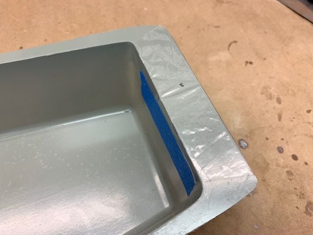
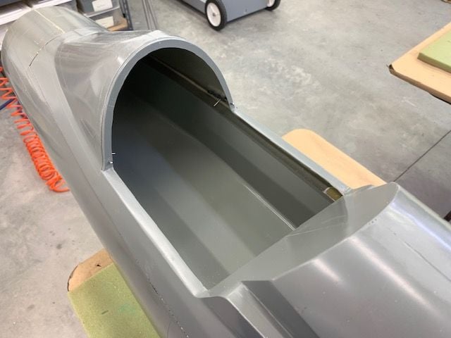
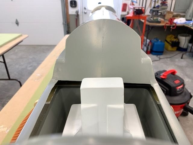
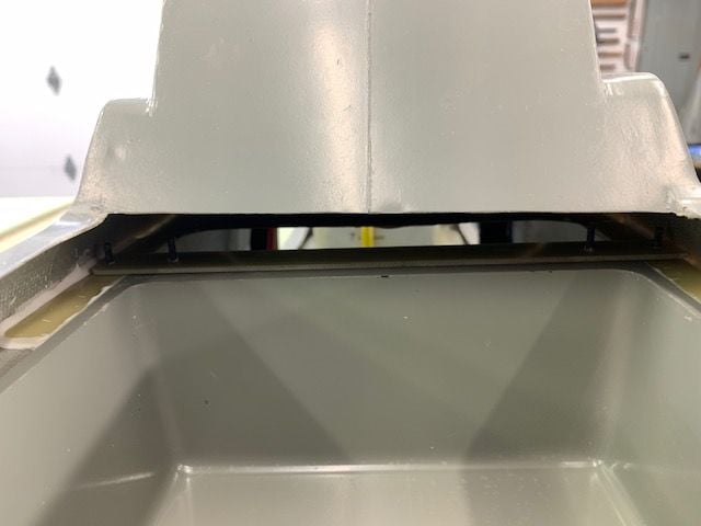
So I got the tub installed to the canopy hatch and was feeling cocky about how it worked out and then I tried some thing really dumb and stupid. I said "lets see how this looks!" Well, as usual, it didn't fit! AARRGGHHH!!!
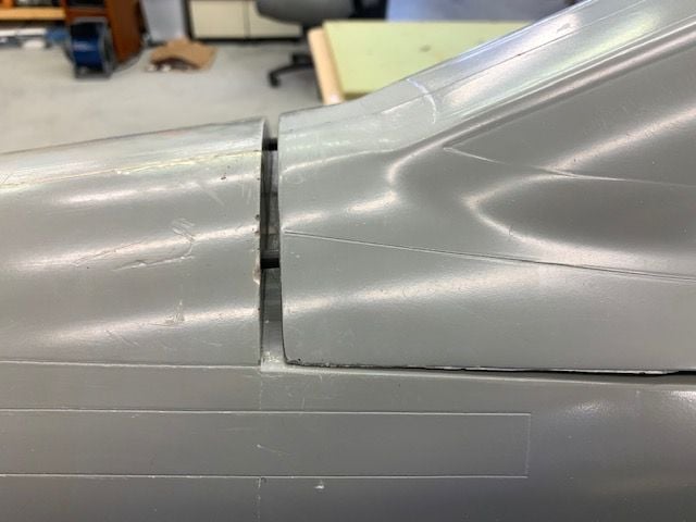
Big gap here...
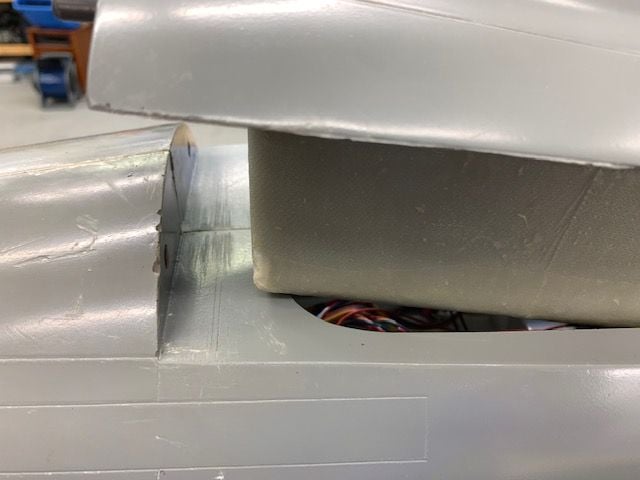
Turned out the tub is hitting the front lip of the fuse opening
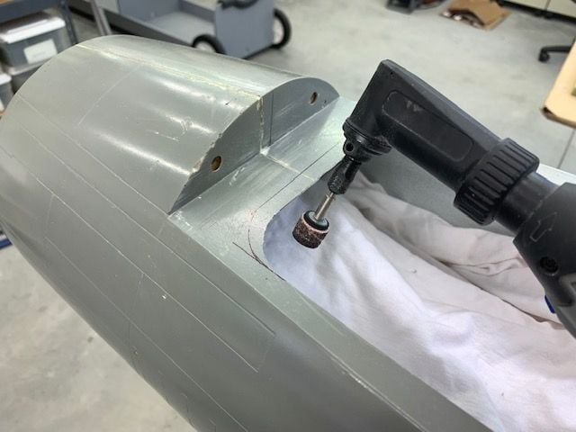
Some measuring, marking, grinding, and sanding and the opening was trimmed out to fit
Fresh cut opening with dust blown out
Canopy hatch fits good now!
Tub inside hatch
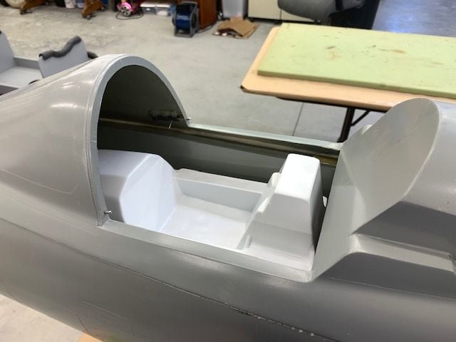
ABS cockpit looks a little small but I'm not building an F-105 cockpit now.
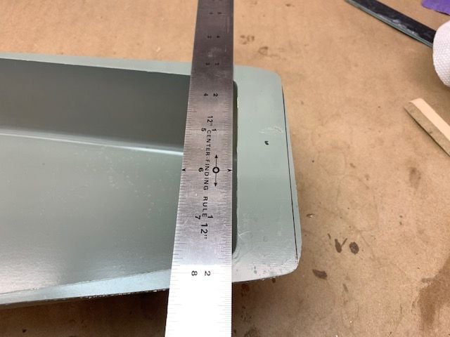
Wait a minute! It'd tilted to the right. What gives... I took everything out and measured the tub and it is square, 3" deep. I don't know. If you build a cockpit that leans to the left it will look ok from the outside. It just goes along with the left wing being thinner than the right....
If you build a cockpit that leans to the left it will look ok from the outside. It just goes along with the left wing being thinner than the right.... It will be the next guys problem.
So I got the tub installed to the canopy hatch and was feeling cocky about how it worked out and then I tried some thing really dumb and stupid. I said "lets see how this looks!" Well, as usual, it didn't fit! AARRGGHHH!!!
Big gap here...
Turned out the tub is hitting the front lip of the fuse opening
Some measuring, marking, grinding, and sanding and the opening was trimmed out to fit
Fresh cut opening with dust blown out
Canopy hatch fits good now!
Tub inside hatch
ABS cockpit looks a little small but I'm not building an F-105 cockpit now.
Wait a minute! It'd tilted to the right. What gives... I took everything out and measured the tub and it is square, 3" deep. I don't know. If you build a cockpit that leans to the left it will look ok from the outside. It just goes along with the left wing being thinner than the right....
If you build a cockpit that leans to the left it will look ok from the outside. It just goes along with the left wing being thinner than the right.... It will be the next guys problem.
09-06-2021, 05:10 PM
#930
Thread Starter
My Feedback: (20)
Attaching tub to canopy hatch
No shop time today except for bolting tub to hatch. Epoxy set on 4-40 safety nuts
G-10 strip inserted above the aft lip of the tub.
Bolts inserted
Bolts tightened and done.
No shop time today except for bolting tub to hatch. Epoxy set on 4-40 safety nuts
G-10 strip inserted above the aft lip of the tub.
Bolts inserted
Bolts tightened and done.
09-07-2021, 05:08 PM
#931
Thread Starter
My Feedback: (20)
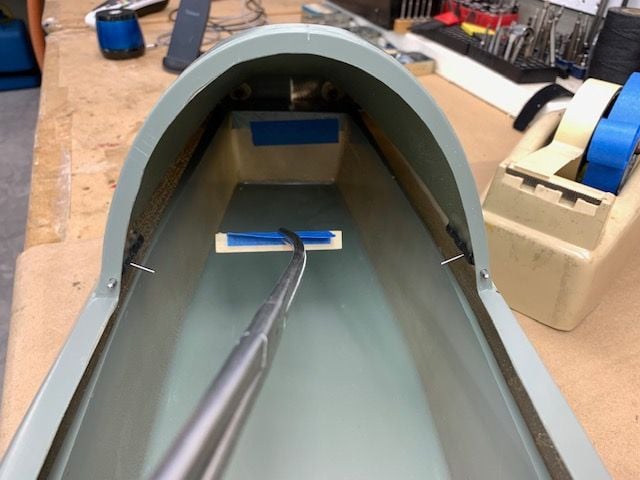
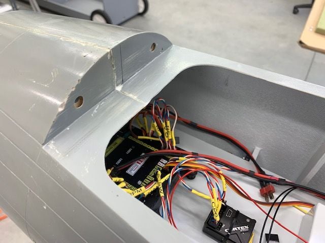
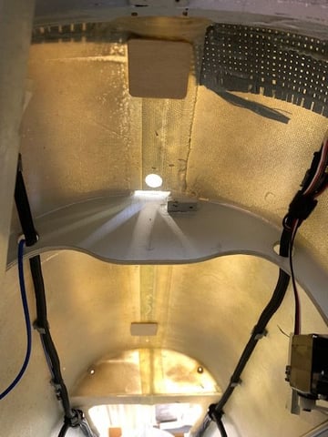
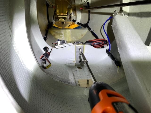
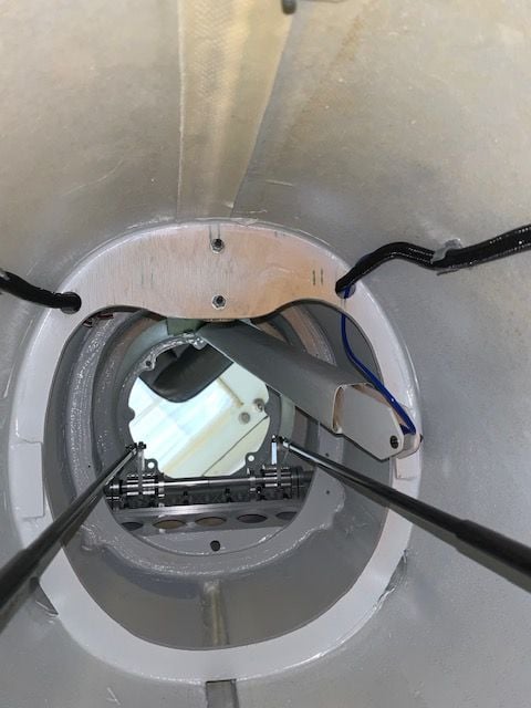
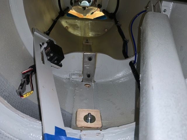
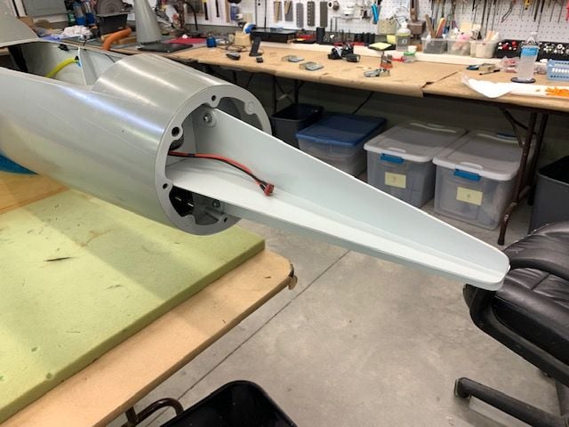
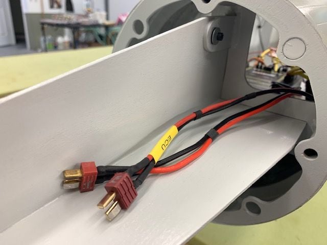
Power leads and antenna
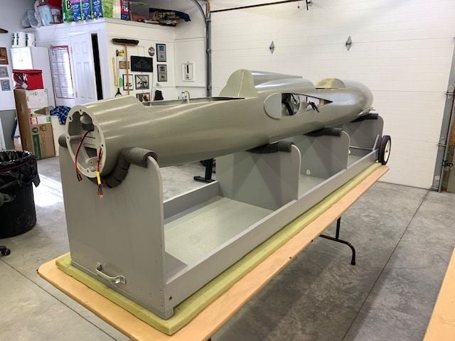
Power leads for both flight batteries and ECU battery installed. Batteries will be mounted in nose cone for initial weight and balance tests
Photo from the early days shows the CF in the forward fuse at the rear nose gear former. I needed to keep the antenna away from this area.
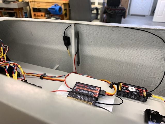
Right side shows primary 2.4 forward antenna vertical mount and right side vertical 900 blade antenna
Right side aft shows primary 2.4 aft antenna mounted horizontal behind the CF area
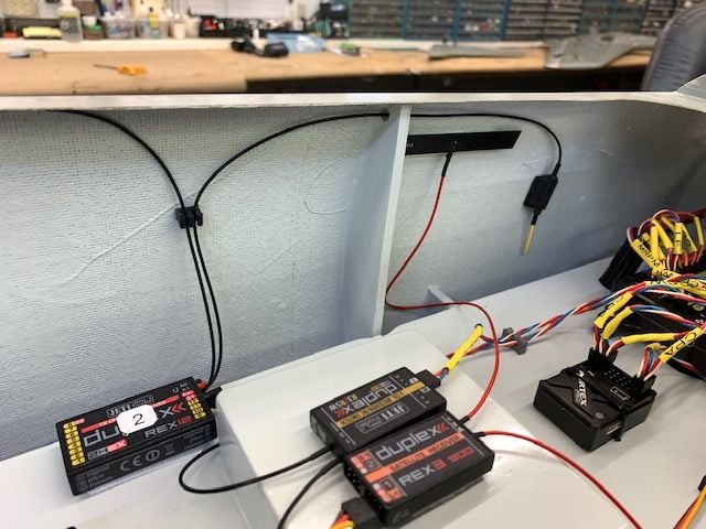
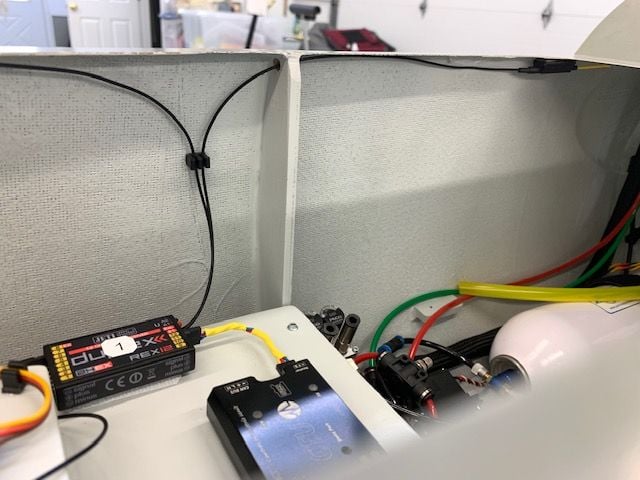
Left side forward shows secondary 2.4 forward antenna vertical mount and left side horizontal 900 blade antenna
Left side shows aft secondary 2.4 antenna mounted horizontal just behind CF area. We'll find out if all this works during power on range checks and 900 backup switch over tests
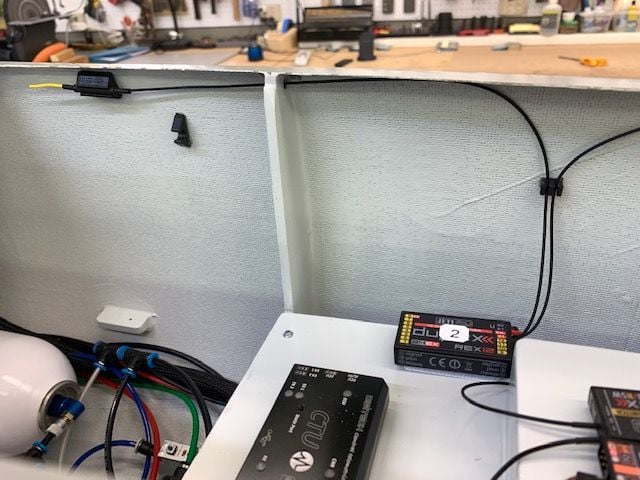
Antenna update
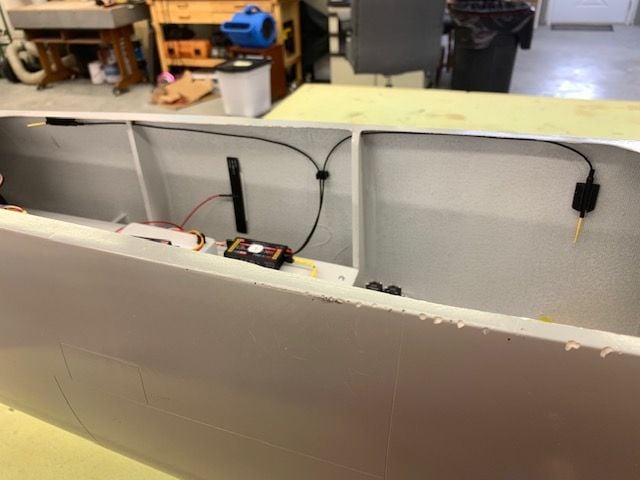
looking at it the next day, I did not like the 2.4 and 900 antenna so close and also got to thinking there may be a strip of CF under the former like it was on the rear former. The photo shows a shadow line there but I don't remember seeing it before. So I moved the front 2.4 to horizontal, moved the 900 vertical blade back between the formers and attached the aft 2.4 vertical behind the CF area. I like this much better.
Power leads for both flight batteries and ECU battery installed. Batteries will be mounted in nose cone for initial weight and balance tests
Photo from the early days shows the CF in the forward fuse at the rear nose gear former. I needed to keep the antenna away from this area.
Right side shows primary 2.4 forward antenna vertical mount and right side vertical 900 blade antenna
Right side aft shows primary 2.4 aft antenna mounted horizontal behind the CF area
Left side forward shows secondary 2.4 forward antenna vertical mount and left side horizontal 900 blade antenna
Left side shows aft secondary 2.4 antenna mounted horizontal just behind CF area. We'll find out if all this works during power on range checks and 900 backup switch over tests
Antenna update
looking at it the next day, I did not like the 2.4 and 900 antenna so close and also got to thinking there may be a strip of CF under the former like it was on the rear former. The photo shows a shadow line there but I don't remember seeing it before. So I moved the front 2.4 to horizontal, moved the 900 vertical blade back between the formers and attached the aft 2.4 vertical behind the CF area. I like this much better.
Last edited by Viper1GJ; 09-08-2021 at 02:07 PM.
09-08-2021, 02:09 PM
#932
Thread Starter
My Feedback: (20)
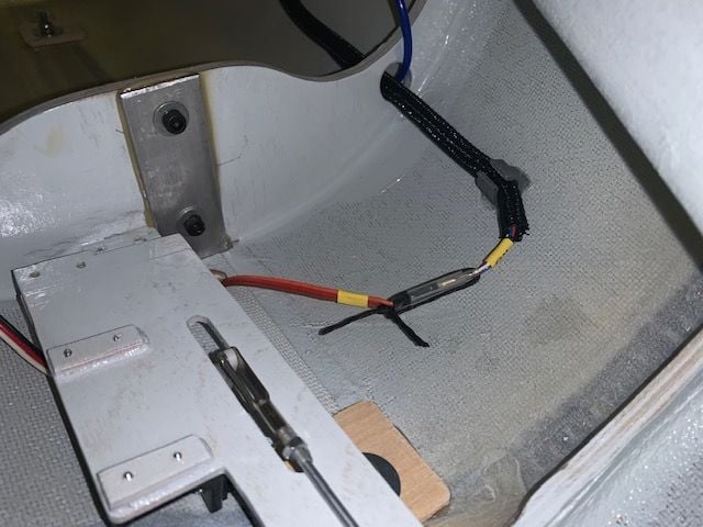
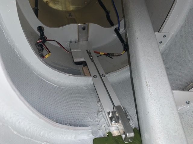
Fuel tray installed
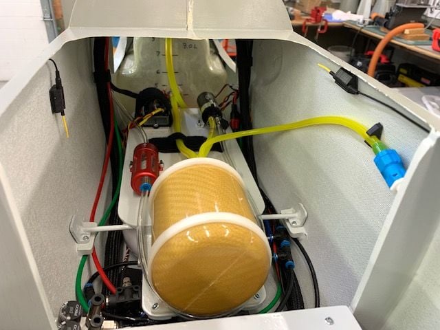
I installed the fuel tray and made all the connections except the safety wire on the air trap fuel intake fitting. I'll delay that till all testing is done in case I have to remove the fuel tray for some reason. I hooked up all the batteries and turned on the systems. The ECU, CTU, pump, and turbine and telemetry all worked. I was shocked!
Vertical fin install to go...
Done for the week now. Packing the trailer tomorrow for a weekend meet.
 09-15-2021, 11:17 PM
#934

Hey Gary,
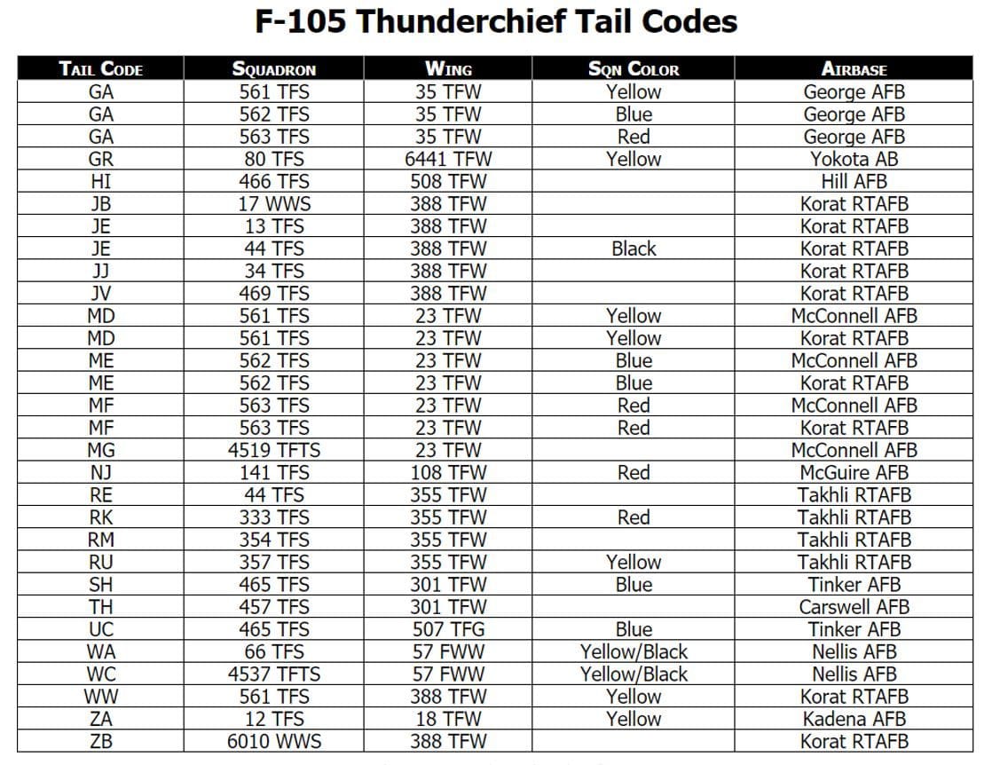
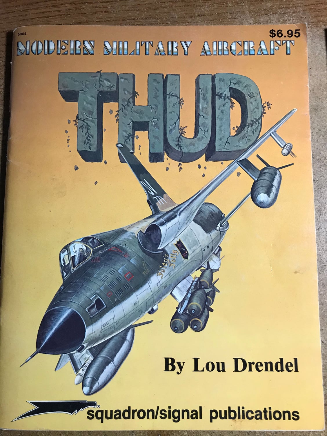
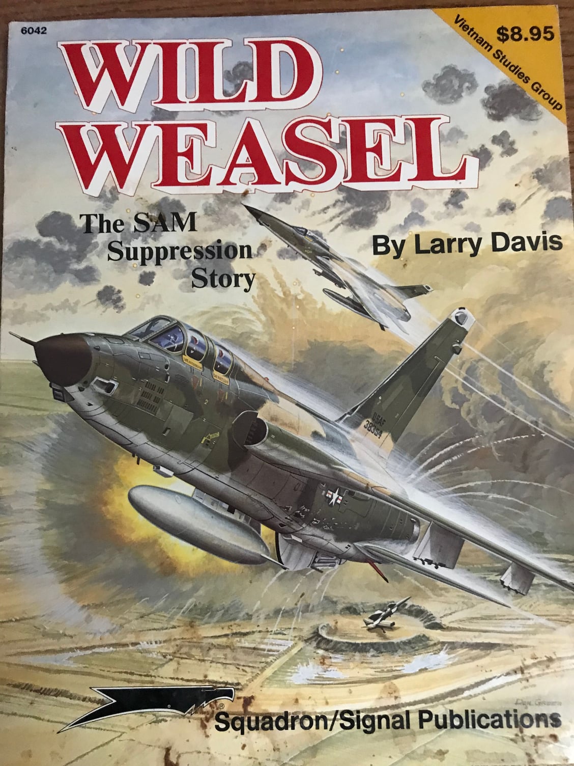
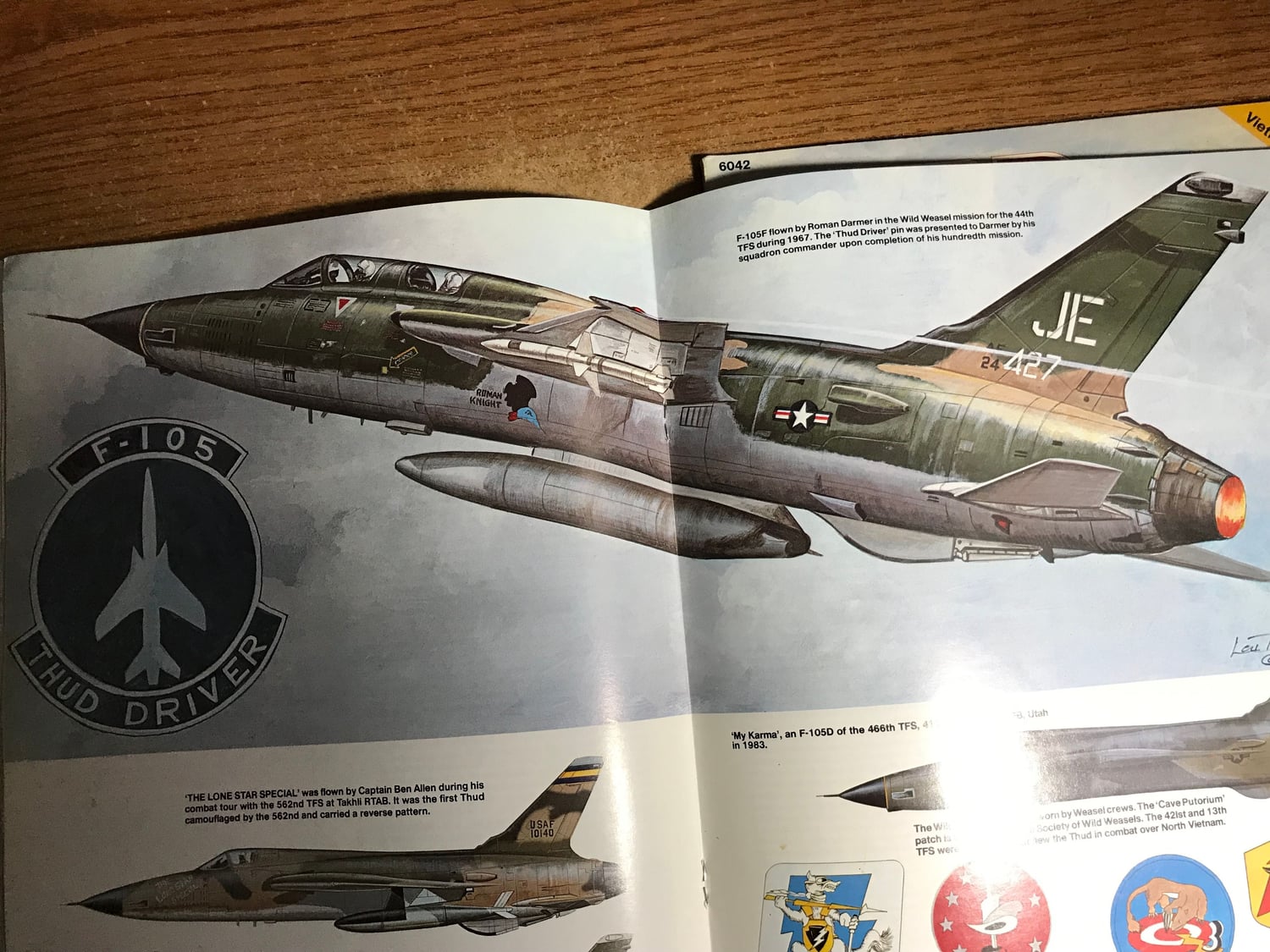
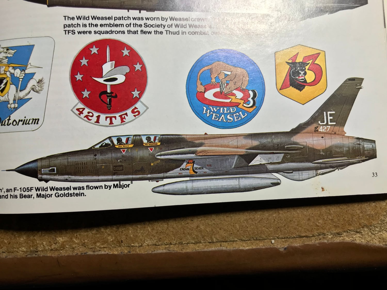
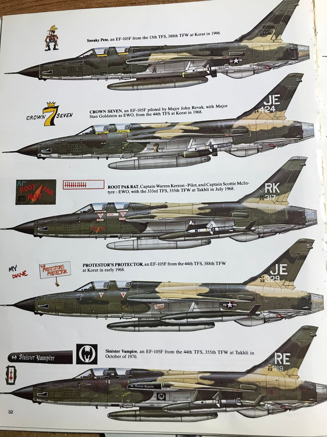
I was curious to see if I had any photos of a F-105 from the 13th TFS with JE tail marking in a really old book published in Jan. 1973 I got from my Dad many years ago. Well I was able to find only two images, but unfortunately it�s a two-seater F-105F in the SEA scheme. Here are some of the images I grabbed from the book. There are lots of photos in this book of single seat F-105Ds with different tail markings. I think you can find those online most likely. My favorite is RE 086 (Big Sal). Anyway thought I�d give it a shot. Enjoy the pictures!
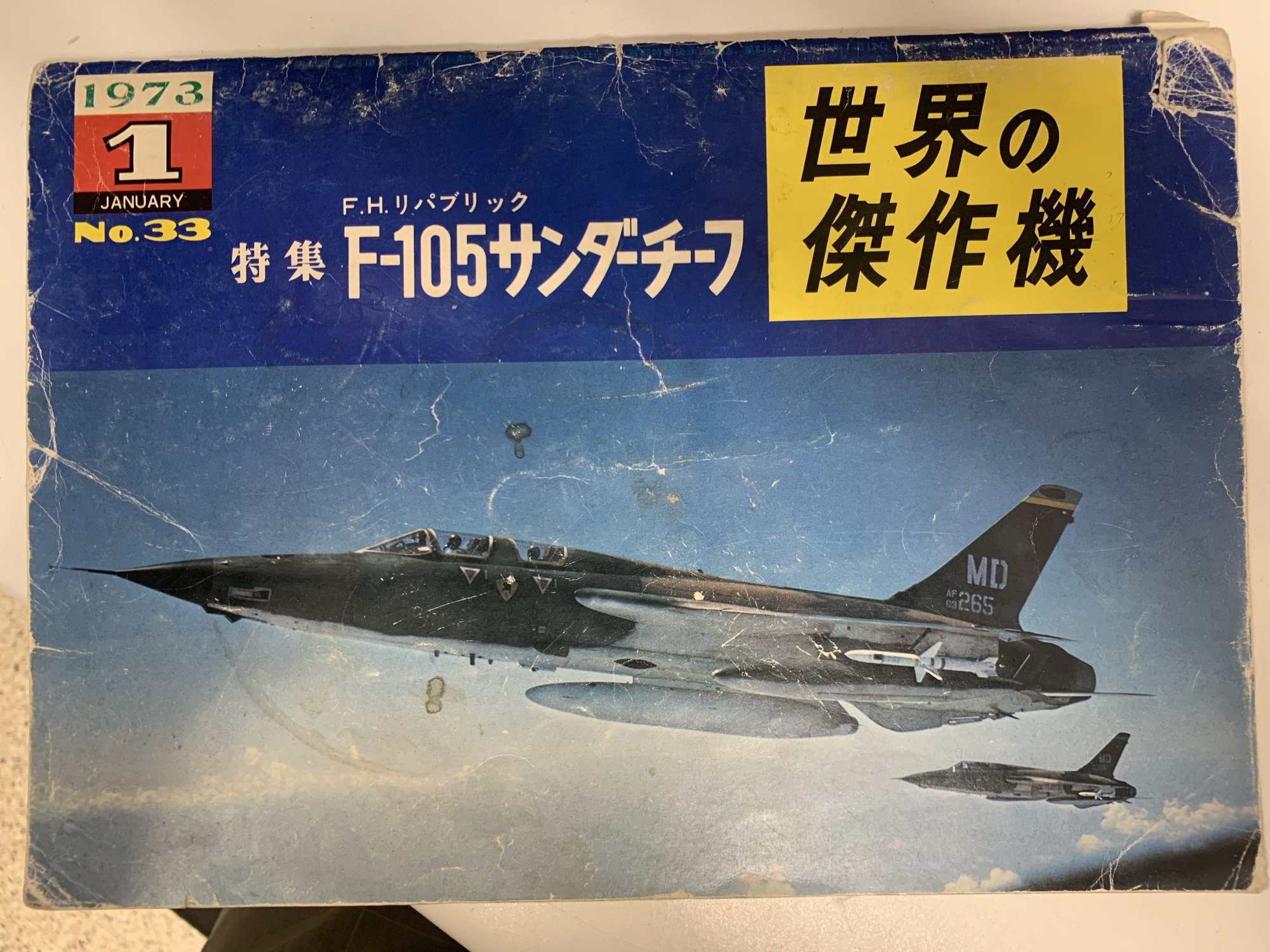
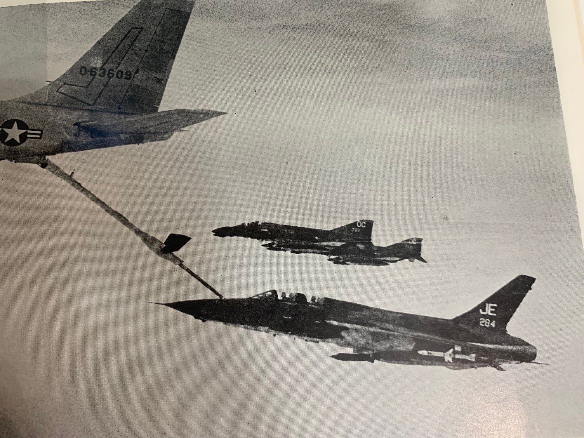
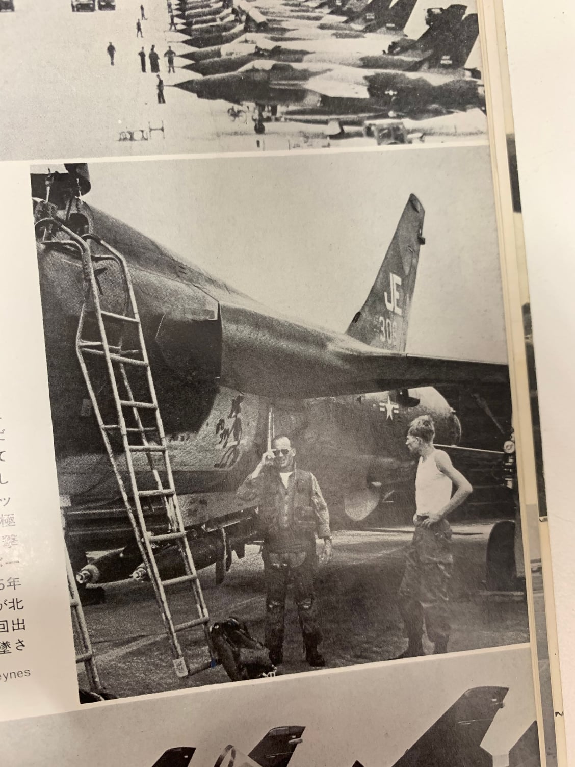
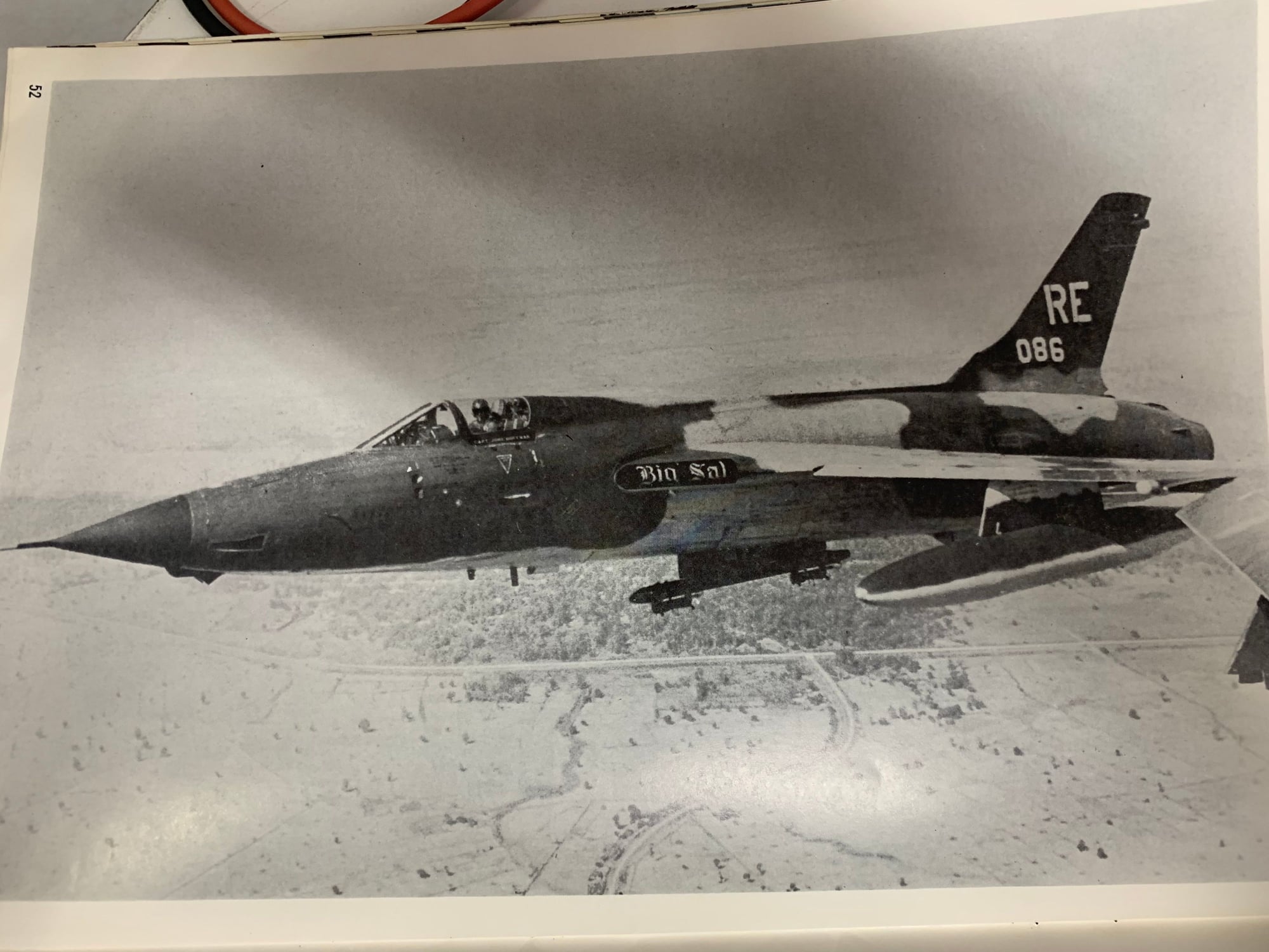
I was curious to see if I had any photos of a F-105 from the 13th TFS with JE tail marking in a really old book published in Jan. 1973 I got from my Dad many years ago. Well I was able to find only two images, but unfortunately it�s a two-seater F-105F in the SEA scheme. Here are some of the images I grabbed from the book. There are lots of photos in this book of single seat F-105Ds with different tail markings. I think you can find those online most likely. My favorite is RE 086 (Big Sal). Anyway thought I�d give it a shot. Enjoy the pictures!
09-17-2021, 02:21 PM
#935
Thread Starter
My Feedback: (20)
Hey Gary,
I was curious to see if I had any photos of a F-105 from the 13th TFS with JE tail marking in a really old book published in Jan. 1973 I got from my Dad many years ago. Well I was able to find only two images, but unfortunately it�s a two-seater F-105F in the SEA scheme. Here are some of the images I grabbed from the book. There are lots of photos in this book of single seat F-105Ds with different tail markings. I think you can find those online most likely. My favorite is RE 086 (Big Sal). Anyway thought I�d give it a shot. Enjoy the pictures!
I was curious to see if I had any photos of a F-105 from the 13th TFS with JE tail marking in a really old book published in Jan. 1973 I got from my Dad many years ago. Well I was able to find only two images, but unfortunately it�s a two-seater F-105F in the SEA scheme. Here are some of the images I grabbed from the book. There are lots of photos in this book of single seat F-105Ds with different tail markings. I think you can find those online most likely. My favorite is RE 086 (Big Sal). Anyway thought I�d give it a shot. Enjoy the pictures!
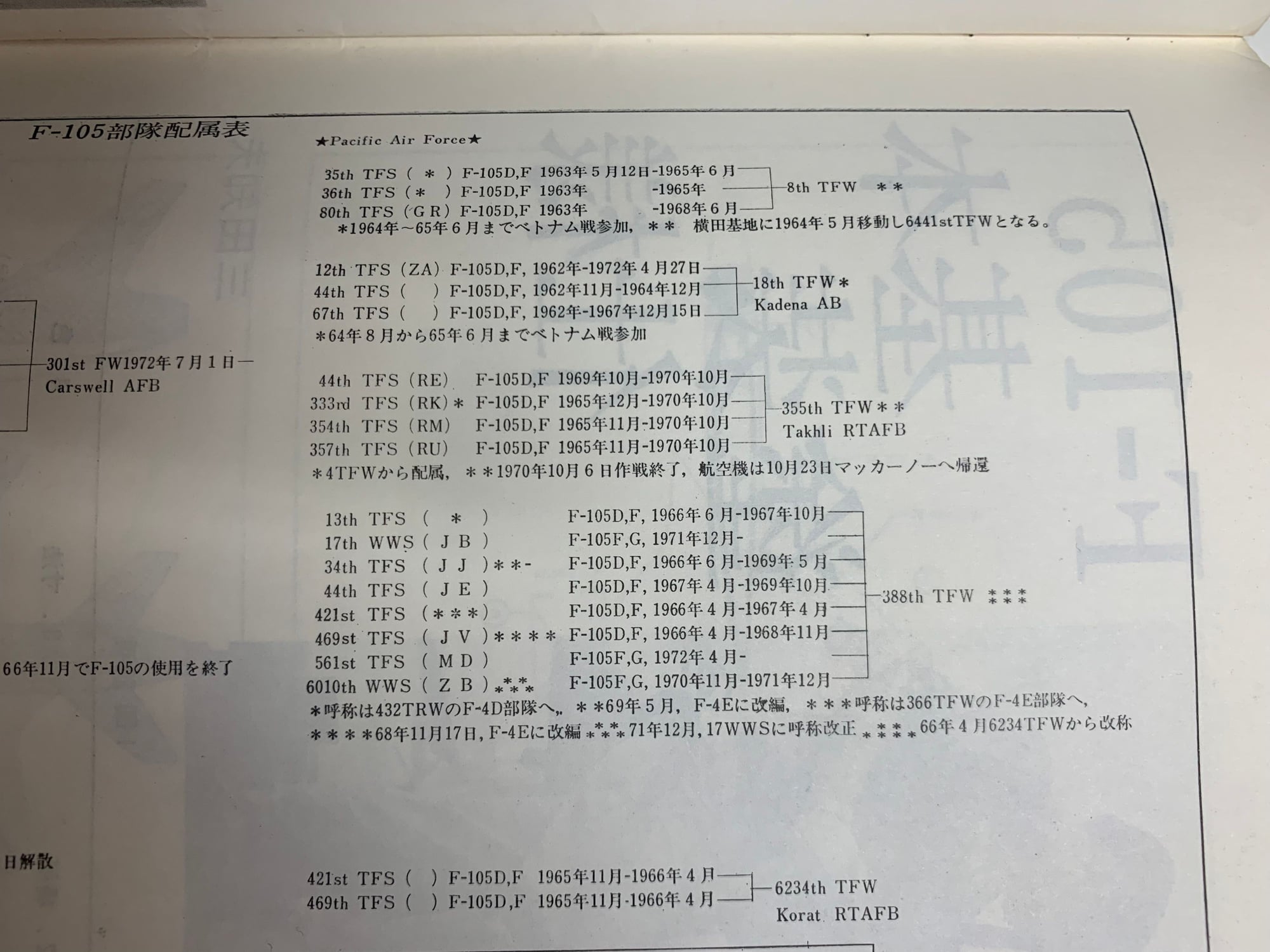
Here is a chart I found but it does not include the 421st.
Thanks,
Gary
09-17-2021, 04:33 PM
#936

I finally dug out my last 2 Thud books. Think my kids swiped the rest..
I'm on the road for 3 weeks starting tomorrow. Maybe I can do a better scan when I'm back.
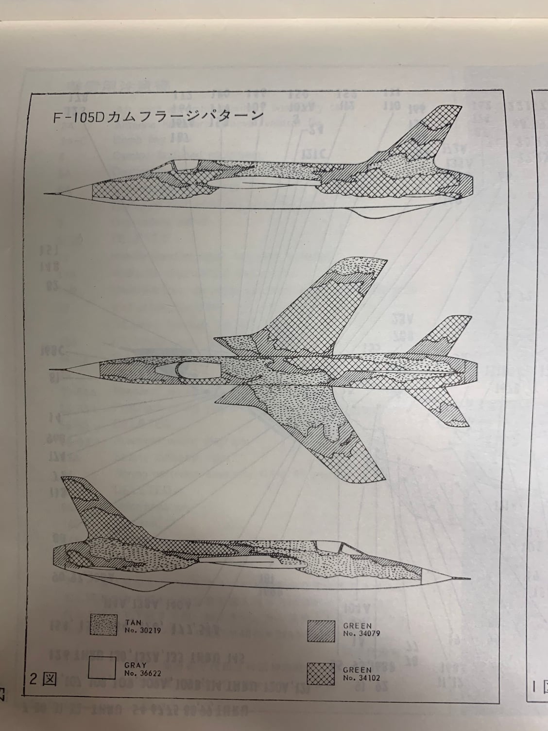
There really isn't much difference between the paint jobs on the D, F, & G. Usually it's just squadron & wing markings and maybe some art or names.
I'm on the road for 3 weeks starting tomorrow. Maybe I can do a better scan when I'm back.
There really isn't much difference between the paint jobs on the D, F, & G. Usually it's just squadron & wing markings and maybe some art or names.
11-29-2021, 06:01 PM
#937
Thread Starter
My Feedback: (20)
I finally dug out my last 2 Thud books. Think my kids swiped the rest..
I'm on the road for 3 weeks starting tomorrow. Maybe I can do a better scan when I'm back.
There really isn't much difference between the paint jobs on the D, F, & G. Usually it's just squadron & wing markings and maybe some art or names.
I'm on the road for 3 weeks starting tomorrow. Maybe I can do a better scan when I'm back.
There really isn't much difference between the paint jobs on the D, F, & G. Usually it's just squadron & wing markings and maybe some art or names.
Gary
11-29-2021, 06:16 PM
#938
Thread Starter
My Feedback: (20)
I see it's been about 2 months since I got any work done on the 105. I remember going to jet meets in OCT and NOV and being busy enough to not get much RC work done since. I plan on getting the 105 back on the table soon and testing the gear swing with the new main gear doors. After that it will be CG checks, turbine starts, runups, and taxi tests, and range checks. After that we will see.
I'm 70 now and can not move the big jets around like in the past. All my other big jets are gone and this is the only one left. I struggle with moving it around and with wings on it is a 2 person job to get it off the table or cradle. We will see how it goes but this one could be looking for a new home.
I'm 70 now and can not move the big jets around like in the past. All my other big jets are gone and this is the only one left. I struggle with moving it around and with wings on it is a 2 person job to get it off the table or cradle. We will see how it goes but this one could be looking for a new home.
Last edited by Viper1GJ; 11-29-2021 at 06:18 PM.
11-30-2021, 10:22 AM
#939
All the F-105's ended up with similar paint schemes. Mostly it came down to whoever had the spray gun in hand on how exactly it came out.
There are decent pictures of the right side of the jet on Airliners.net. I didn't see any marked JE except one F-105G #274. May not matter if you're not trying to do an exact match to a particular tail number.
There are decent pictures of the right side of the jet on Airliners.net. I didn't see any marked JE except one F-105G #274. May not matter if you're not trying to do an exact match to a particular tail number.
Last edited by Thud_Driver; 11-30-2021 at 10:24 AM.
12-02-2021, 03:40 PM
#942
Thread Starter
My Feedback: (20)
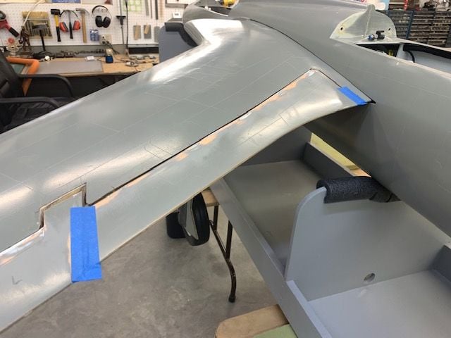
Gear swing tests with main gear doors attached
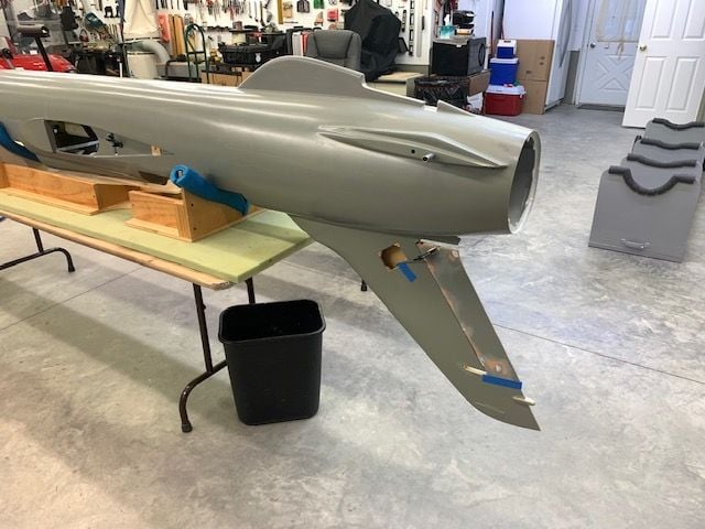
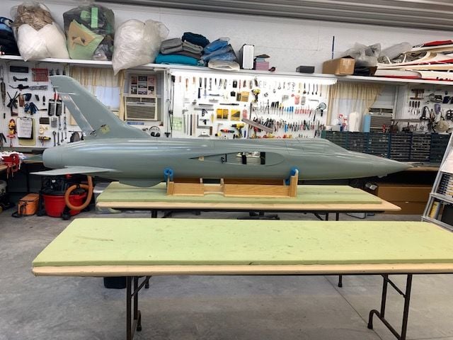
Finally got the Thud back on the work table.
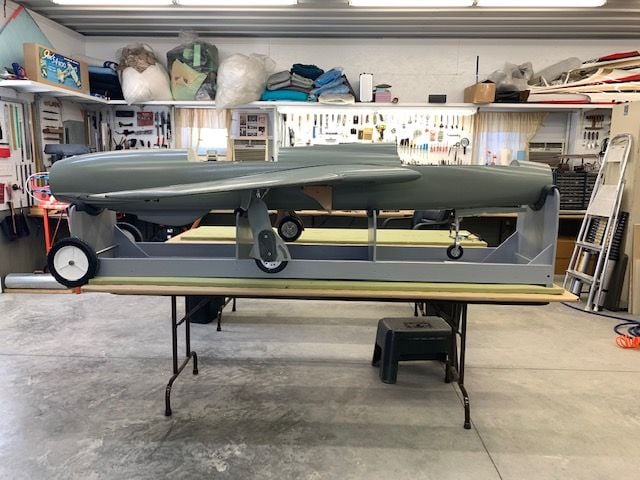
Got the wings on and did multiple gear swing tests
The main doors work good but they are not perfect. There still is a small droop on the door leading edge below the surface of the wing skin but it is as good as I can get it. The trailing edges fit good. There is no way to curve the doors any more without rubbing the wheels. The final fix will have to be a bead of body filler around the bottom leading edge of the main doors to make them flush. Otherwise they work ok. It's time to move on, get the vertical tail on, and final assembly.
Finally got the Thud back on the work table.
Got the wings on and did multiple gear swing tests
The main doors work good but they are not perfect. There still is a small droop on the door leading edge below the surface of the wing skin but it is as good as I can get it. The trailing edges fit good. There is no way to curve the doors any more without rubbing the wheels. The final fix will have to be a bead of body filler around the bottom leading edge of the main doors to make them flush. Otherwise they work ok. It's time to move on, get the vertical tail on, and final assembly.
Last edited by Viper1GJ; 12-02-2021 at 03:43 PM.
The following users liked this post:
Mark Basel (12-03-2021)
12-02-2021, 04:00 PM
#943
Thread Starter
My Feedback: (20)
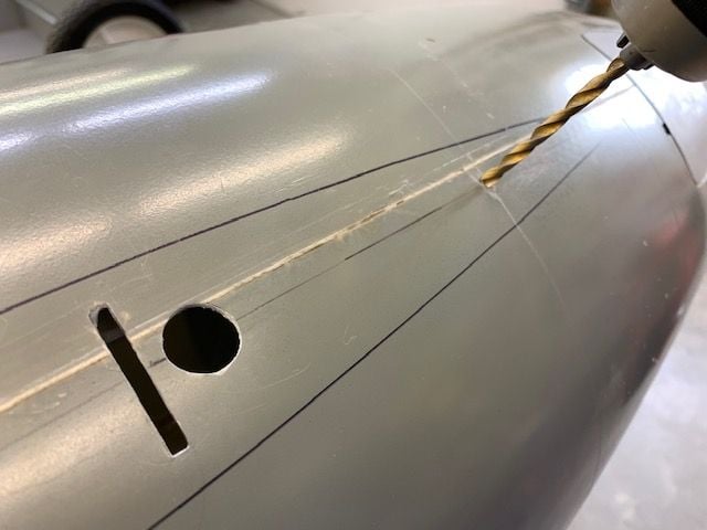
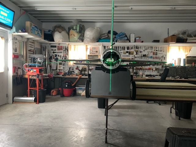
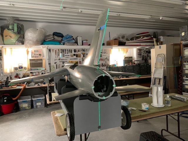
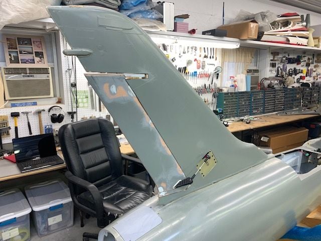
Vertical fin assembly test
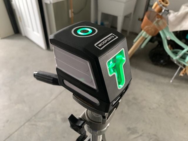
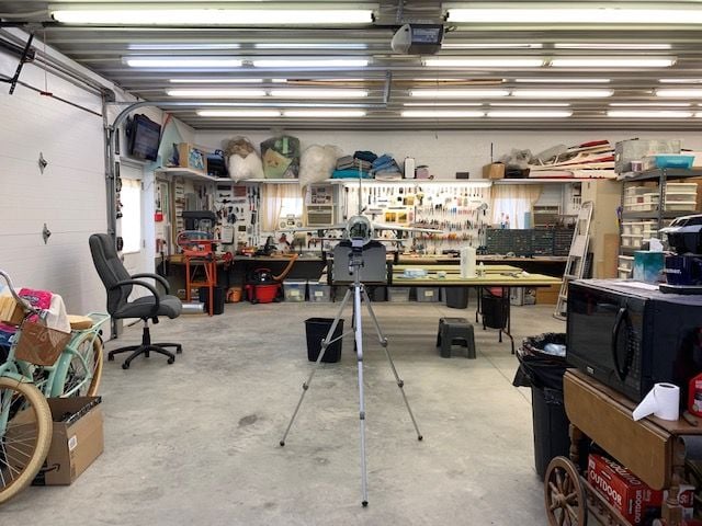
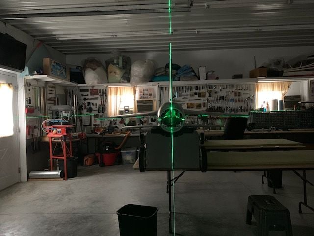
The next step is attaching the vertical fin. I wanted to try out my planned alignment method before committing to drilling and epoxy. First, I mounted a laser level on the tripod behind jet.
After getting everything set up and adjusted, the laser projects two perpendicular lines that can be used to level the wings and fit the vertical fin perpendicular to the wings. I turned the jet 90 left on the table so I would have some back up distance behind the tail to see if the TLAR method matches the laser.
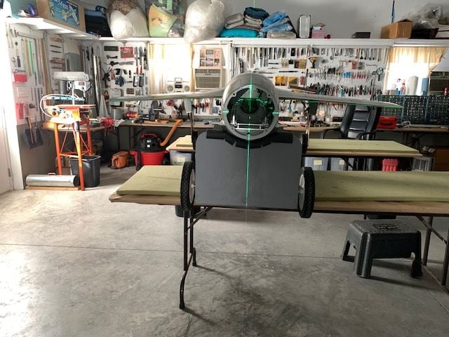
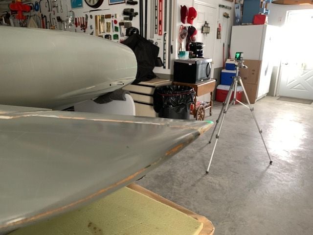
The wings are leveled using the horizontal line. You can see the green line on the wing tips if you look close.
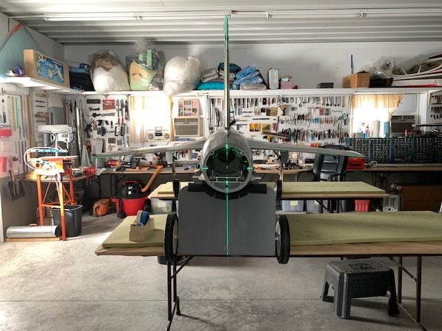
With wings level the vertical fin can be aligned with the green line and clamped in place. I turned off the shop lights to make the green lines move visible, but this was mid day and the sun was washing out the green lines. Once the fin is clamped in the two attachment bolt holes can be drilled in the proper location to keep the fin perpendicular to the wings. With a couple of adjustments I think this method will work ok.
The next step is attaching the vertical fin. I wanted to try out my planned alignment method before committing to drilling and epoxy. First, I mounted a laser level on the tripod behind jet.
After getting everything set up and adjusted, the laser projects two perpendicular lines that can be used to level the wings and fit the vertical fin perpendicular to the wings. I turned the jet 90 left on the table so I would have some back up distance behind the tail to see if the TLAR method matches the laser.
The wings are leveled using the horizontal line. You can see the green line on the wing tips if you look close.
With wings level the vertical fin can be aligned with the green line and clamped in place. I turned off the shop lights to make the green lines move visible, but this was mid day and the sun was washing out the green lines. Once the fin is clamped in the two attachment bolt holes can be drilled in the proper location to keep the fin perpendicular to the wings. With a couple of adjustments I think this method will work ok.
Last edited by Viper1GJ; 12-02-2021 at 04:03 PM.
The following 4 users liked this post by Viper1GJ:
12-08-2021, 05:58 PM
#944
Thread Starter
My Feedback: (20)
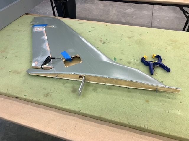
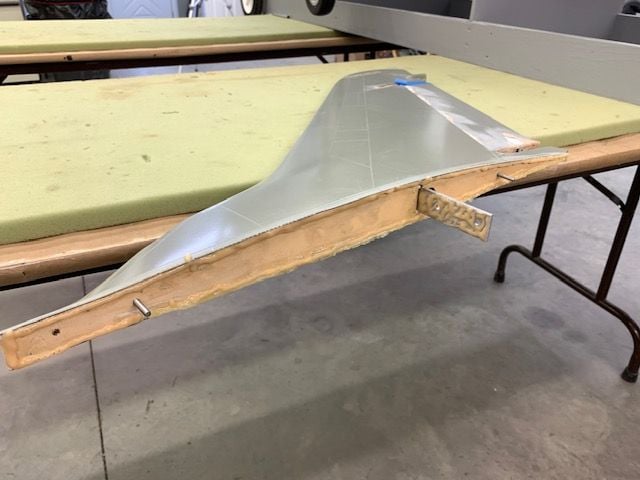
Vertical fin epoxied to fuse
This is the very last major build step. I held it off to the very end to avoid having to fight the big fin as I moved, rolled, and lifted the fuse during the build process. 8-32 washers and nylon safety nuts were fitted to the studs sticking out of the bottom of the fin. The holes in the aluminum spar were drilled out for 8-32 bolts.
1/8" plywood plates epoxied to inside top of the fuse to accept the 8-32 stud bolts
Stud bolt plates drilled. The fin outline was scuff sanded after the photo was taken.
The fuse was set in the cradle and wings and stabs were attached to the fuse again. The flaps and ailerons were taped into neutral position.
The Laser level was turned on, aligned, and the wings were set to level. The fin was test fit and last adjustments made.
Rudder servo removed and clamp ready
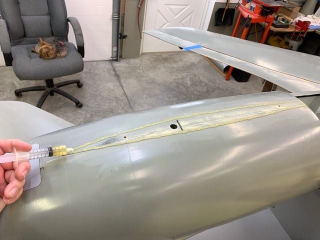
Six10 epoxy laid on fuse where carbon skins of fin make contact
I ran out of SIx10 and switched to Total Boat THIXO epoxy on the bottom of the fin. The fin root rib is slightly recessed inside the fin so the epoxy was only applied on the edges where contact with fuse is made. Epoxy was applied to front of aluminum spar and to rudder former inside the fuse. THIXO has a slightly darker color and is slightly thicker than Six10.
Vertical fin placed in position and alignment verified.
The clamp was applied to keep the fin in position during cure.
Lights turned on and a visual check made from a distance to make sure the TLAR alignment matches the Laser alignment.
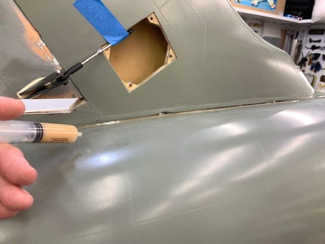
A "finger" fillet of epoxy laid in on both sides of the fin

Fillet smoothed in on left side
Alignment verified again and left overnight for epoxy cure
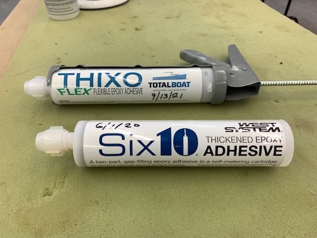
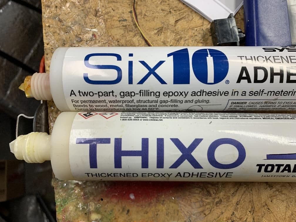
Here are the two epoxies I used. I was told THIXO was a rebranded Six10 by the vender but it is not. It is a different formula, slightly thicker and a different color. I could not tell much difference in the end results but I think Six10 is easier to work with since it is a little thinner. Both are thixotropic. THIXO is a little cheaper than Six10 and both are way cheaper than Hysol. For our use either will work but I think I prefer Six10 because of the thinner paste.
This is the very last major build step. I held it off to the very end to avoid having to fight the big fin as I moved, rolled, and lifted the fuse during the build process. 8-32 washers and nylon safety nuts were fitted to the studs sticking out of the bottom of the fin. The holes in the aluminum spar were drilled out for 8-32 bolts.
1/8" plywood plates epoxied to inside top of the fuse to accept the 8-32 stud bolts
Stud bolt plates drilled. The fin outline was scuff sanded after the photo was taken.
The fuse was set in the cradle and wings and stabs were attached to the fuse again. The flaps and ailerons were taped into neutral position.
The Laser level was turned on, aligned, and the wings were set to level. The fin was test fit and last adjustments made.
Rudder servo removed and clamp ready
Six10 epoxy laid on fuse where carbon skins of fin make contact
I ran out of SIx10 and switched to Total Boat THIXO epoxy on the bottom of the fin. The fin root rib is slightly recessed inside the fin so the epoxy was only applied on the edges where contact with fuse is made. Epoxy was applied to front of aluminum spar and to rudder former inside the fuse. THIXO has a slightly darker color and is slightly thicker than Six10.
Vertical fin placed in position and alignment verified.
The clamp was applied to keep the fin in position during cure.
Lights turned on and a visual check made from a distance to make sure the TLAR alignment matches the Laser alignment.
A "finger" fillet of epoxy laid in on both sides of the fin
Fillet smoothed in on left side
Alignment verified again and left overnight for epoxy cure
Here are the two epoxies I used. I was told THIXO was a rebranded Six10 by the vender but it is not. It is a different formula, slightly thicker and a different color. I could not tell much difference in the end results but I think Six10 is easier to work with since it is a little thinner. Both are thixotropic. THIXO is a little cheaper than Six10 and both are way cheaper than Hysol. For our use either will work but I think I prefer Six10 because of the thinner paste.
The following users liked this post:
grbaker (12-08-2021)
12-08-2021, 06:20 PM
#945
Thread Starter
My Feedback: (20)
Vertical fin and stabs final assembly
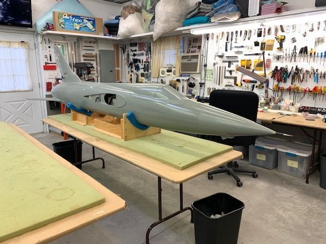
Wings were removed and fuse set on table for final assembly. This is why I waited till the end to attach the fin. It's huge and in the way!
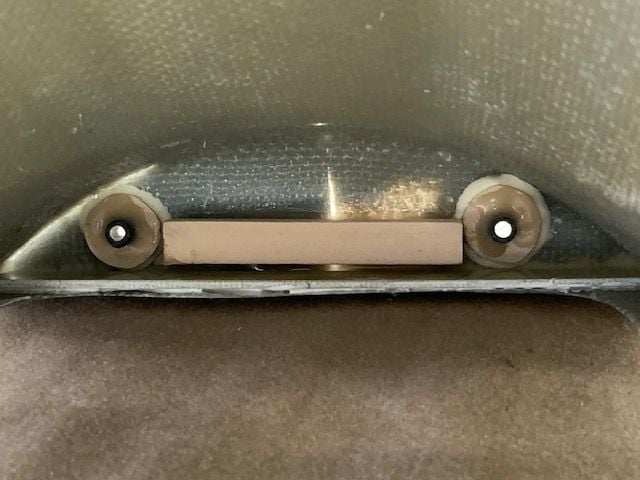
Bolt holes in spar drilled through the fin former and 8-32 bolts installed.
8-32 nylon safety nuts on front side of former.
8-32 safety nuts and washers tightened down on the fin stud bolts.
Rudder servo connected and connector safety tied with waxed thread.
Drag chute jettison servo and pushrod screwed in place
Rudder servo installed and top and bottom caps installed on rudder
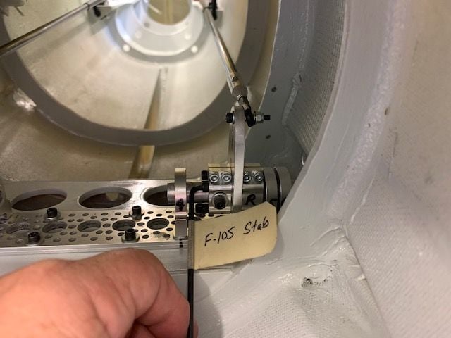
Both stabs installed and all the stab control arm screws tightened. The horizontal clamp screws require a modified hex wrench to fit in the tight space.
Wings were removed and fuse set on table for final assembly. This is why I waited till the end to attach the fin. It's huge and in the way!
Bolt holes in spar drilled through the fin former and 8-32 bolts installed.
8-32 nylon safety nuts on front side of former.
8-32 safety nuts and washers tightened down on the fin stud bolts.
Rudder servo connected and connector safety tied with waxed thread.
Drag chute jettison servo and pushrod screwed in place
Rudder servo installed and top and bottom caps installed on rudder
Both stabs installed and all the stab control arm screws tightened. The horizontal clamp screws require a modified hex wrench to fit in the tight space.
The following users liked this post:
grbaker (12-08-2021)
12-08-2021, 06:52 PM
#946
Thread Starter
My Feedback: (20)
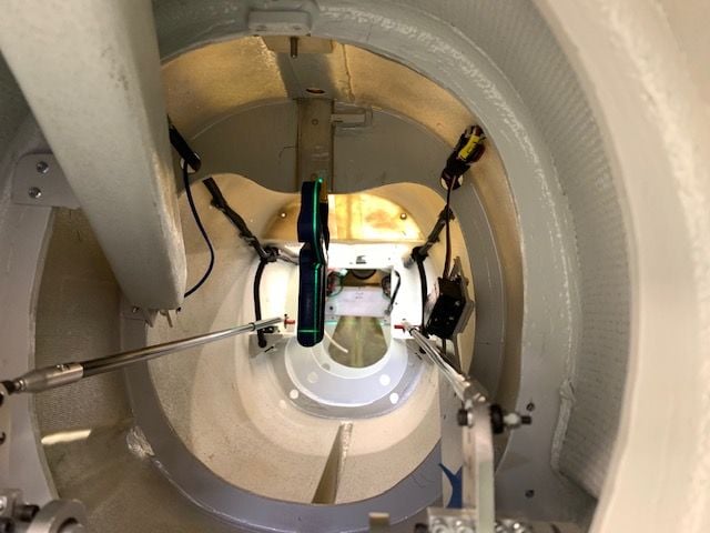
Fuse final assembly
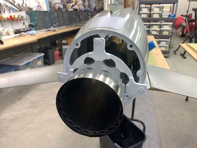
The pipe has to be installed with the bell mouth removed in order to fit past the drag chute tube. Once the pipe is inside the fuse the pipe ring was slipped over the aft end of the pipe
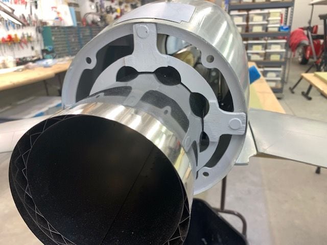
The magnets lock the pipe ring onto the aft fuse former
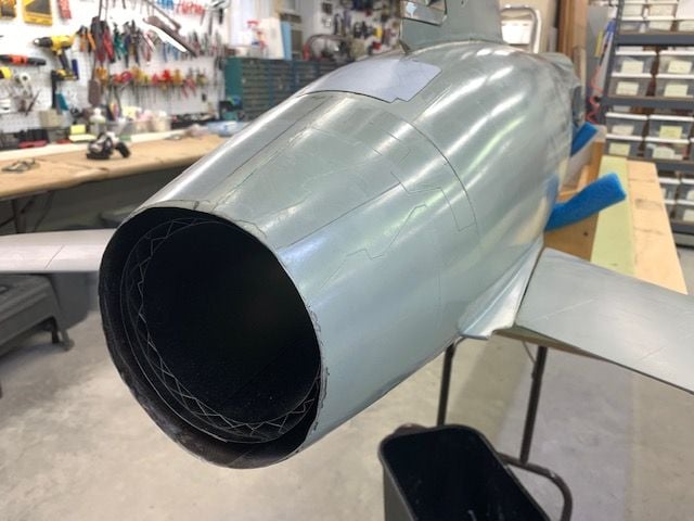
The nozzle section slips into the aft fuse former and is locked on with magnets.
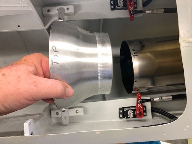
The pipe bell is installed through the turbine hatch
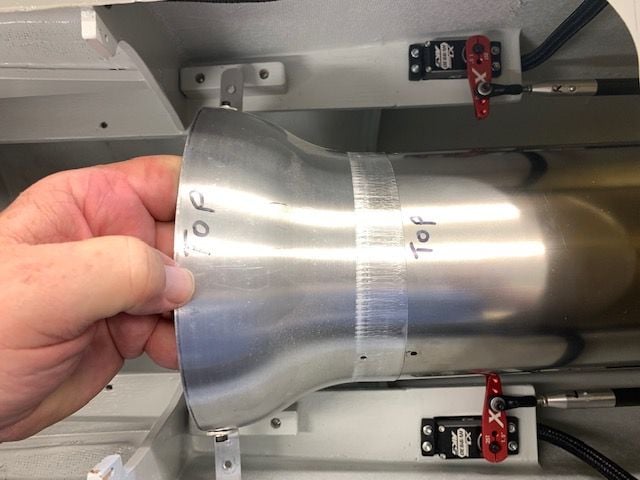
The bell is attached to the pipe with 4 stainless bolts and nuts with star lock washers
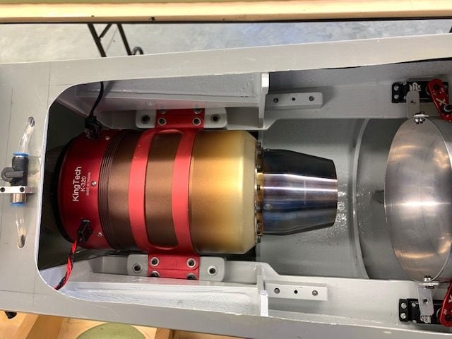
The K-320 turbine is installed with the usual 4 bolts through the plywood spacers.
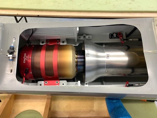
The pipe bell is pulled forward and installed with 2 bolts
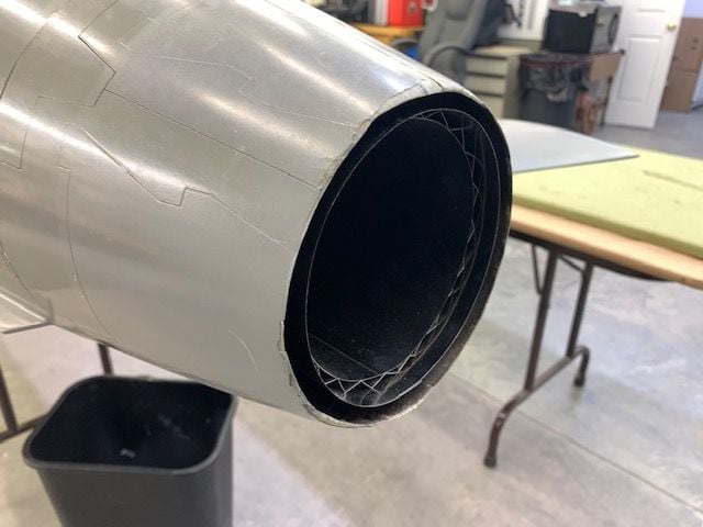
Pipe is nearly flush with the back edge of the nozzle section
Nose rack is installed with two bolts and rubber sealing washers
Battery locations and mounting method is TBD. There are lots of options.
Nose radome installed with magnets. I copied the method from the CARF Rebel Max.
It's done! The next guy will get to figure out the canopy, cockpit, and paint.
My next step is to see if I can get it from the table the cradle on the ground. Then will come the first install of wings from ground level. That will require laying on the ground and looking up into the bottom of the wheel well to install the 4 outboard wing spar screws on both sides. Kind of like a car mechanic on a crawler under the car.
Then comes the real task. Getting it out of the cradle on to the wheels. Then some ops checks, fuel system tests, and turbine start. To be continued.
The pipe has to be installed with the bell mouth removed in order to fit past the drag chute tube. Once the pipe is inside the fuse the pipe ring was slipped over the aft end of the pipe
The magnets lock the pipe ring onto the aft fuse former
The nozzle section slips into the aft fuse former and is locked on with magnets.
The pipe bell is installed through the turbine hatch
The bell is attached to the pipe with 4 stainless bolts and nuts with star lock washers
The K-320 turbine is installed with the usual 4 bolts through the plywood spacers.
The pipe bell is pulled forward and installed with 2 bolts
Pipe is nearly flush with the back edge of the nozzle section
Nose rack is installed with two bolts and rubber sealing washers
Battery locations and mounting method is TBD. There are lots of options.
Nose radome installed with magnets. I copied the method from the CARF Rebel Max.
It's done! The next guy will get to figure out the canopy, cockpit, and paint.
My next step is to see if I can get it from the table the cradle on the ground. Then will come the first install of wings from ground level. That will require laying on the ground and looking up into the bottom of the wheel well to install the 4 outboard wing spar screws on both sides. Kind of like a car mechanic on a crawler under the car.
Then comes the real task. Getting it out of the cradle on to the wheels. Then some ops checks, fuel system tests, and turbine start. To be continued.
The following users liked this post:
grbaker (12-08-2021)
12-08-2021, 06:53 PM
#947

Hey Gary, I see you are using the Thixo Flex which is supposed to be more shock resistant than the regular Thixo I use. I was thinking of trying the Flex. Do you notice much difference? The regular seems a lighter color than yours also.
Last edited by causeitflies; 12-08-2021 at 07:00 PM.
12-08-2021, 07:01 PM
#948
Thread Starter
My Feedback: (20)
It's the first time I used it. I did not realize it was the "flex" even though it says it right on the label. Maybe it will be better that the regular if it is more flexible and not brittle. It is a little thicker than Six10 for sure. I will have to try the regular THIXO next time and see.
Thanks, Gary
12-08-2021, 07:04 PM
#949

Fuse final assembly
The pipe has to be installed with the bell mouth removed in order to fit past the drag chute tube. Once the pipe is inside the fuse the pipe ring was slipped over the aft end of the pipe
The magnets lock the pipe ring onto the aft fuse former
The nozzle section slips into the aft fuse former and is locked on with magnets.
The pipe bell is installed through the turbine hatch
The bell is attached to the pipe with 4 stainless bolts and nuts with star lock washers
The K-320 turbine is installed with the usual 4 bolts through the plywood spacers.
The pipe bell is pulled forward and installed with 2 bolts
Pipe is nearly flush with the back edge of the nozzle section
Nose rack is installed with two bolts and rubber sealing washers
Battery locations and mounting method is TBD. There are lots of options.
Nose radome installed with magnets. I copied the method from the CARF Rebel Max.
It's done! The next guy will get to figure out the canopy, cockpit, and paint.
My next step is to see if I can get it from the table the cradle on the ground. Then will come the first install of wings from ground level. That will require laying on the ground and looking up into the bottom of the wheel well to install the 4 outboard wing spar screws on both sides. Kind of like a car mechanic on a crawler under the car.
Then comes the real task. Getting it out of the cradle on to the wheels. Then some ops checks, fuel system tests, and turbine start. To be continued.
are you saying you�re not even going to try and fly this masterpiece of craftsmanship?
12-08-2021, 07:20 PM
#950

Vertical fin epoxied to fuse
This is the very last major build step. I held it off to the very end to avoid having to fight the big fin as I moved, rolled, and lifted the fuse during the build process. 8-32 washers and nylon safety nuts were fitted to the studs sticking out of the bottom of the fin. The holes in the aluminum spar were drilled out for 8-32 bolts.
1/8" plywood plates epoxied to inside top of the fuse to accept the 8-32 stud bolts
Stud bolt plates drilled. The fin outline was scuff sanded after the photo was taken.
The fuse was set in the cradle and wings and stabs were attached to the fuse again. The flaps and ailerons were taped into neutral position.
The Laser level was turned on, aligned, and the wings were set to level. The fin was test fit and last adjustments made.
Rudder servo removed and clamp ready
Six10 epoxy laid on fuse where carbon skins of fin make contact
I ran out of SIx10 and switched to Total Boat THIXO epoxy on the bottom of the fin. The fin root rib is slightly recessed inside the fin so the epoxy was only applied on the edges where contact with fuse is made. Epoxy was applied to front of aluminum spar and to rudder former inside the fuse. THIXO has a slightly darker color and is slightly thicker than Six10.
Vertical fin placed in position and alignment verified.
The clamp was applied to keep the fin in position during cure.
Lights turned on and a visual check made from a distance to make sure the TLAR alignment matches the Laser alignment.
A "finger" fillet of epoxy laid in on both sides of the fin
Fillet smoothed in on left side
Alignment verified again and left overnight for epoxy cure
Here are the two epoxies I used. I was told THIXO was a rebranded Six10 by the vender but it is not. It is a different formula, slightly thicker and a different color. I could not tell much difference in the end results but I think Six10 is easier to work with since it is a little thinner. Both are thixotropic. THIXO is a little cheaper than Six10 and both are way cheaper than Hysol. For our use either will work but I think I prefer Six10 because of the thinner paste.
The following users liked this post:
Viper1GJ (12-18-2021)