


1/6 F-105 Build Thread
 04-07-2021, 05:04 PM
#901

Thread Starter
My Feedback: (20)
Had a few requests for updates on the F-105. No work accomplished since the last post in Feb. The right main gear is still sticking up and I have not made time to work on it since. After I returned from the fly in the first of March I got side tracked working on spring house and yard chores plus a repair on the camper. I did a couple of foamy turbine conversion engine changes and then got started on the F-16 XL I ordered back in December. So the 105 is in the penalty box for a while. I am waiting on the gear rotation blocks so once those parts come in for the gear upgrade I will get back to it. Thanks for following.
Gary
Gary
Last edited by Viper1GJ; 04-07-2021 at 05:07 PM.

The following users liked this post:
bonefishfool (04-08-2021)
05-08-2021, 05:55 PM
#902
Thread Starter
My Feedback: (20)
Landing gear rotation blocks arrived.
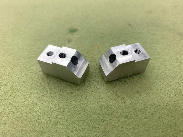
I got these blocks machined by Larry today. This hopefully will solve the rotation angle problems. I'm currently working on my F-16XL now getting ready for FIF. I hope ot get back to the F-105 project in June.
I got these blocks machined by Larry today. This hopefully will solve the rotation angle problems. I'm currently working on my F-16XL now getting ready for FIF. I hope ot get back to the F-105 project in June.
The following users liked this post:
bonefishfool (05-08-2021)
08-22-2021, 04:16 PM
#903
Thread Starter
My Feedback: (20)
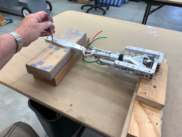
Main gear alignment blocks installed
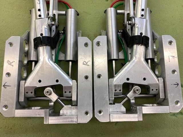
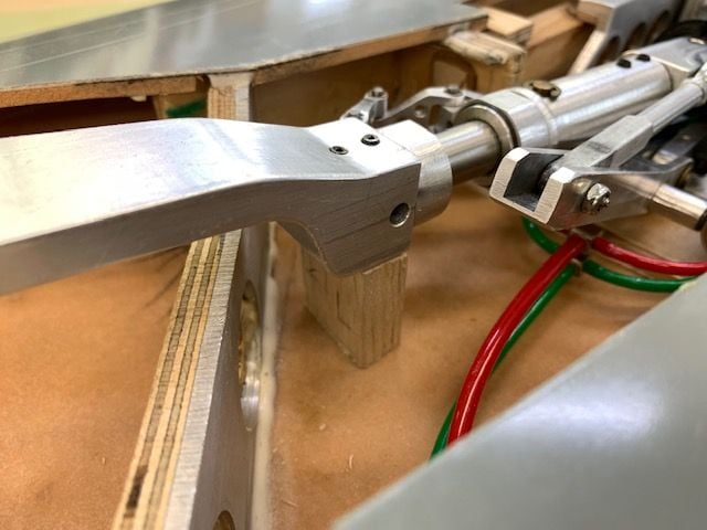
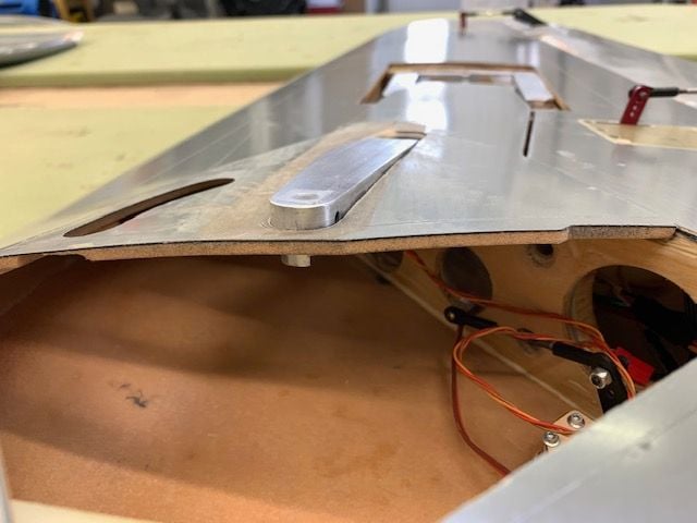
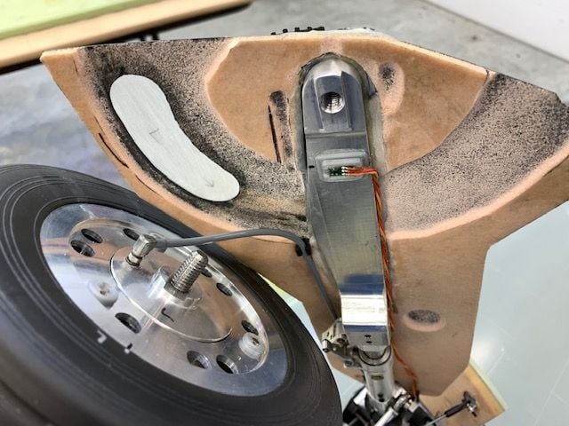
After a long delay the F-105 landed back on the work table. Summer is over, my wife's summer trips are over, grandkids started school, and hopefully some steady shop time in upcoming weeks. I installed the main gear rotation blocks that Larry sent me back in May. Both blocks installed quickly and with no binding. Perfect machining by Larry developing a retrofit part into the existing gear assembly.
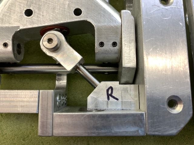
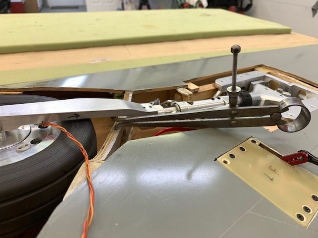
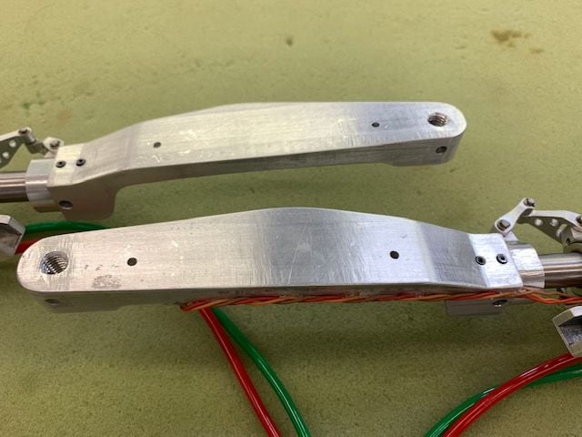
The new blocks fit perfectly and have the proper angle for the rotation pin seen here.
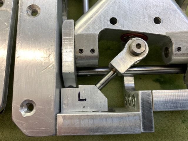
The cutout on top allows the gear trunnion to rotate with clearance from the block.
Gear ready to reinstall and test alignment. My shop supervisor is in the grey chair.
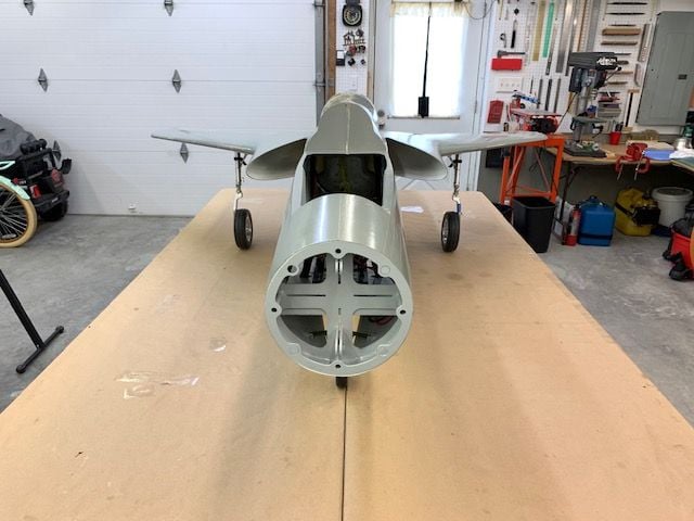
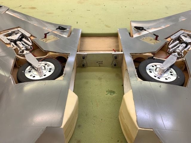
Success! The main gear now align perfectly when extended and the wheels fit inside the gear well when retracted.

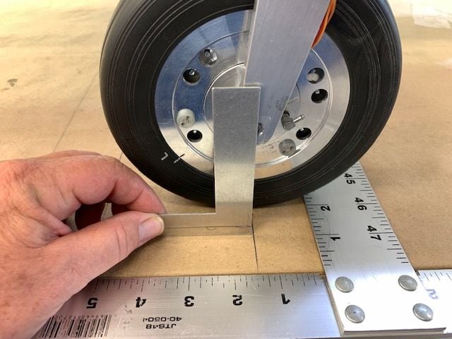
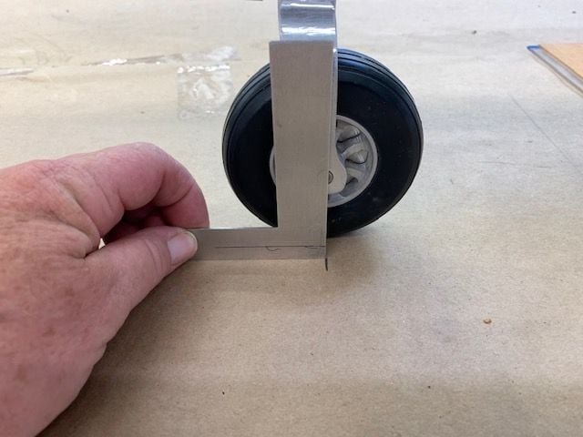
Left main wheel aligned with pencil line on table

Same for right. The unacceptable tow angle is gone. This was the number one problem that I identified when starting this project 3 years ago. Many thanks and great work Larry.
After a long delay the F-105 landed back on the work table. Summer is over, my wife's summer trips are over, grandkids started school, and hopefully some steady shop time in upcoming weeks. I installed the main gear rotation blocks that Larry sent me back in May. Both blocks installed quickly and with no binding. Perfect machining by Larry developing a retrofit part into the existing gear assembly.
The new blocks fit perfectly and have the proper angle for the rotation pin seen here.
The cutout on top allows the gear trunnion to rotate with clearance from the block.
Gear ready to reinstall and test alignment. My shop supervisor is in the grey chair.
Success! The main gear now align perfectly when extended and the wheels fit inside the gear well when retracted.
Left main wheel aligned with pencil line on table
Same for right. The unacceptable tow angle is gone. This was the number one problem that I identified when starting this project 3 years ago. Many thanks and great work Larry.
The following users liked this post:
skunkwurk (08-22-2021)

The following users liked this post:
Viper1GJ (08-22-2021)
08-22-2021, 04:54 PM
#905
Thread Starter
My Feedback: (20)
Initial weight and balance
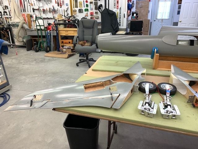
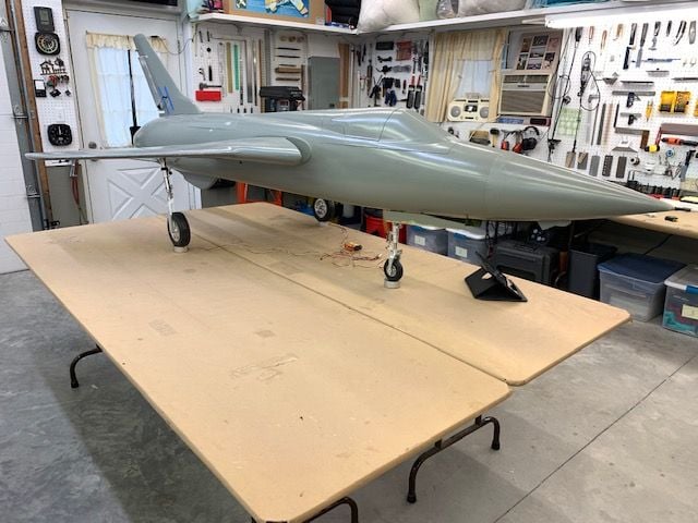
I decided to do the first weight and balance test while the wings were attached since it is a chore to put them on. I wanted to find out just how bad the bad news was going to be, so I did a full dress rehearsal by loading all the components and parts on the jet to get it as close as possible to final weight less fuel. Batteries, turbine, pipe, drag chute, etc, etc.
After building up the jet I squared it up on the table and marked the positions of the main gear and nose gear
Nose gear position marked
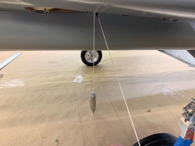
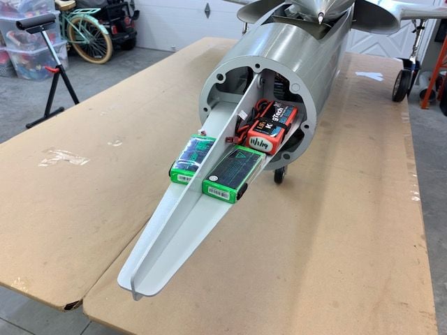
I used a plum bob to locate the CG under the main wing spar where Bob told me he flew his back in 2019.
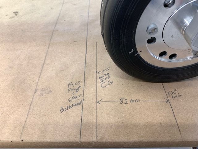
Measurements for Xicoy CG Machine marked on table. The plum bob marked the front of the spar bulkhead and the actual spar is 15mm behind the plum bob line. This leaves 82mm from MLG to CG.
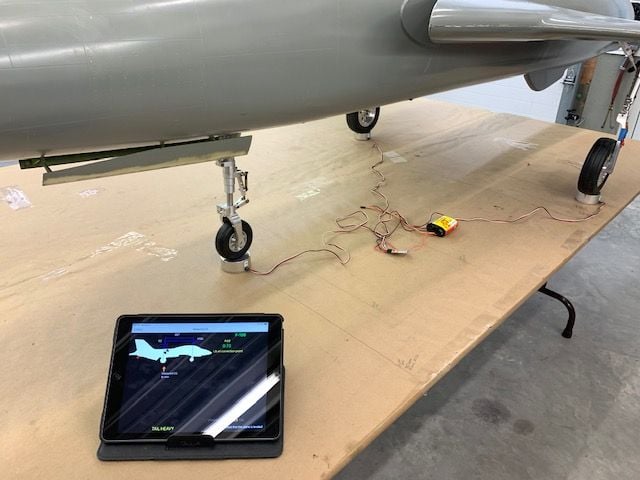
The moment of truth when you find out just how bad it is going to be....
...and I was shocked!
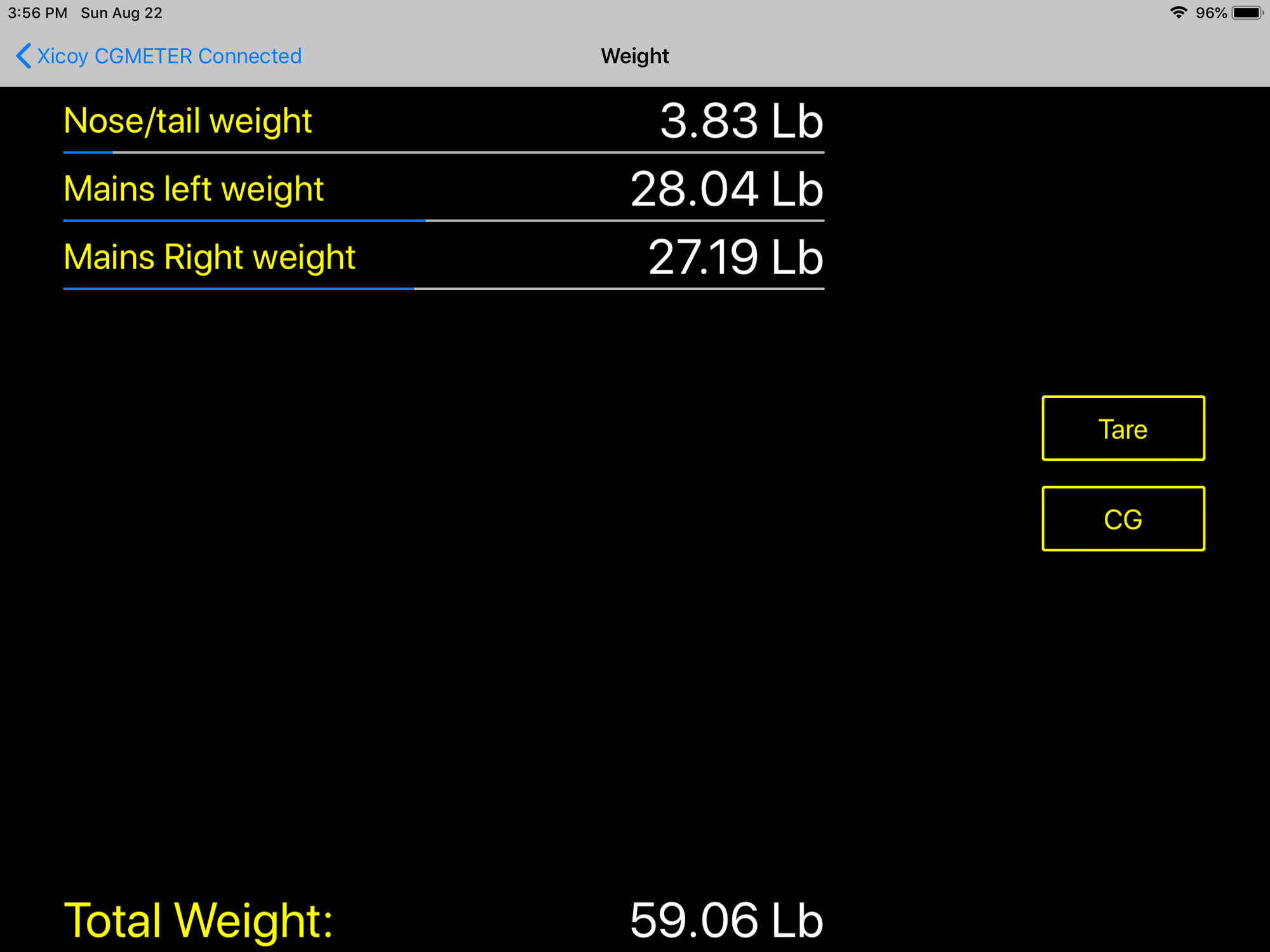
I expected to see 70 lbs or more... but it was only 59 lbs! I was dumbfounded! I was sure it was much heavier, but here it is. It will be LTMA2 for sure with fuel but not nearly as bad as I thought.
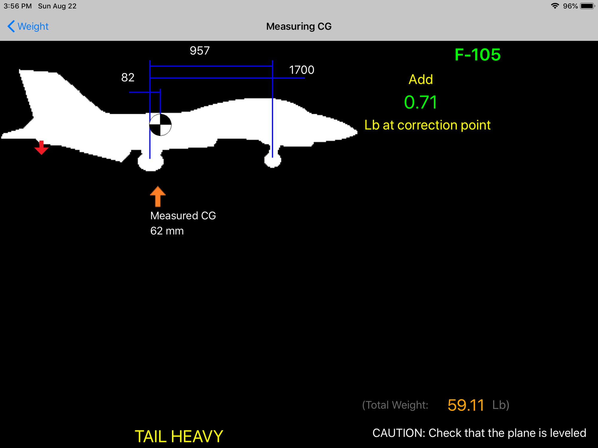
What's more amazing is I thought it would take a massive nose weight to offset the long tail and heavy vertical fin and stabs, but it was nearly balanced now with just batteries in the nose. It does not account for air trap tank fuel, cockpit, or pilot. So I was so pleased that there will not be much ballast needed if any at all.
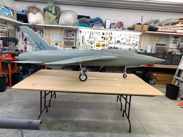
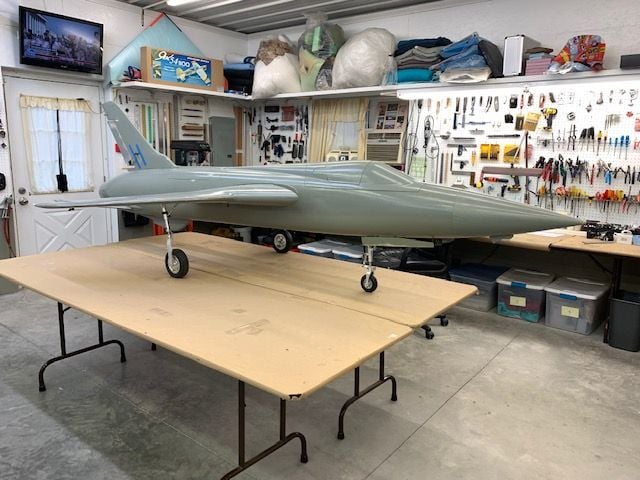
With two bits of good news today I took some happy snaps for motivation.
Next steps are mounting main gear doors on the main strut.
I decided to do the first weight and balance test while the wings were attached since it is a chore to put them on. I wanted to find out just how bad the bad news was going to be, so I did a full dress rehearsal by loading all the components and parts on the jet to get it as close as possible to final weight less fuel. Batteries, turbine, pipe, drag chute, etc, etc.
After building up the jet I squared it up on the table and marked the positions of the main gear and nose gear
Nose gear position marked
I used a plum bob to locate the CG under the main wing spar where Bob told me he flew his back in 2019.
Measurements for Xicoy CG Machine marked on table. The plum bob marked the front of the spar bulkhead and the actual spar is 15mm behind the plum bob line. This leaves 82mm from MLG to CG.
The moment of truth when you find out just how bad it is going to be....
...and I was shocked!
I expected to see 70 lbs or more... but it was only 59 lbs! I was dumbfounded! I was sure it was much heavier, but here it is. It will be LTMA2 for sure with fuel but not nearly as bad as I thought.
What's more amazing is I thought it would take a massive nose weight to offset the long tail and heavy vertical fin and stabs, but it was nearly balanced now with just batteries in the nose. It does not account for air trap tank fuel, cockpit, or pilot. So I was so pleased that there will not be much ballast needed if any at all.
With two bits of good news today I took some happy snaps for motivation.
Next steps are mounting main gear doors on the main strut.


The following users liked this post:
Viper1GJ (08-29-2021)
08-24-2021, 03:41 PM
#907
Thread Starter
My Feedback: (20)
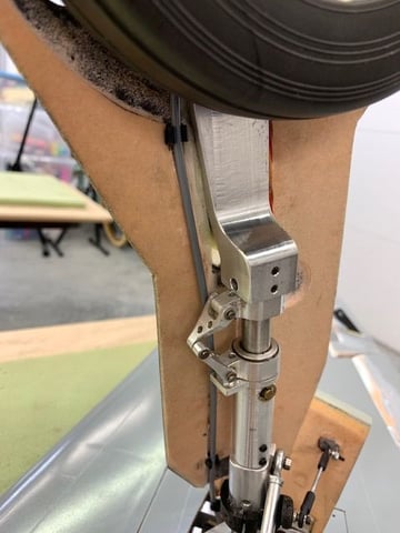
Fitting gear doors to struts
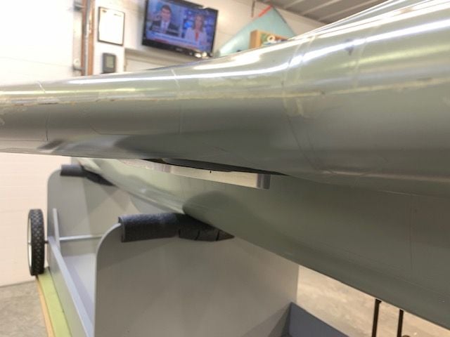
Now that the new gear rotation blocks are installed the wheel goes into the wheel well but the strut hangs out below the bottom wing skin. Right side shown here.
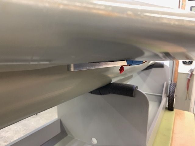
This was a known problem so my plan is to make non scale bump on the gear door to hide the strut.
I measured the distance between the inside of the strut and the wing spar when the wings were still attached and gravity was pulling the slop in the retracts down.
I cut and fit wood blocks to hold the gear in the "gear up" position while the wing is up side down on the table.
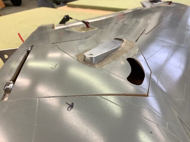
This is the door position prior to making the relief cut for the strut on the left side.
Right side before relief cuts made
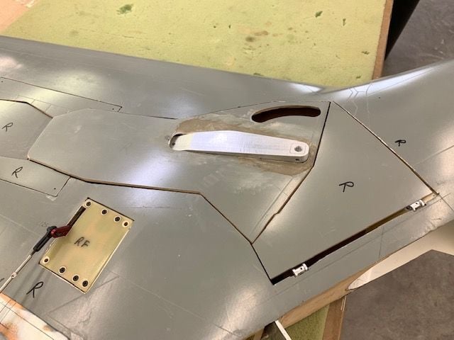
Relief cut for right strut
Cut out for left strut. At least the doors are close to flush now.
The plan is to build the structural bump over the strut with 2 layers of CF and then fare it to the edges or the gear door. Then the gear doors will be mounted to the lower strut by two machine screws drilled through the structural CF bump and tapped into the strut. The inner door will have a matching non structural bump of foam covered by fiberglass fared toward the edges.
Door would not fit very well at first. I found 2 points of contact which had to be ground away.
The wheel brake air fittings were making contact with the door
Relief cut made for air fittings
The 3D printed outer door arm bracket was hitting the door and required another relief cut.
I put the wheel back on to check for fit and its still fighting me! AARRGGHH!
I have to make more relief cuts for the wheels and then cover them up with the bump over the strut. It never ends...
Now that the new gear rotation blocks are installed the wheel goes into the wheel well but the strut hangs out below the bottom wing skin. Right side shown here.
This was a known problem so my plan is to make non scale bump on the gear door to hide the strut.
I measured the distance between the inside of the strut and the wing spar when the wings were still attached and gravity was pulling the slop in the retracts down.
I cut and fit wood blocks to hold the gear in the "gear up" position while the wing is up side down on the table.
This is the door position prior to making the relief cut for the strut on the left side.
Right side before relief cuts made
Relief cut for right strut
Cut out for left strut. At least the doors are close to flush now.
The plan is to build the structural bump over the strut with 2 layers of CF and then fare it to the edges or the gear door. Then the gear doors will be mounted to the lower strut by two machine screws drilled through the structural CF bump and tapped into the strut. The inner door will have a matching non structural bump of foam covered by fiberglass fared toward the edges.
Door would not fit very well at first. I found 2 points of contact which had to be ground away.
The wheel brake air fittings were making contact with the door
Relief cut made for air fittings
The 3D printed outer door arm bracket was hitting the door and required another relief cut.
I put the wheel back on to check for fit and its still fighting me! AARRGGHH!
I have to make more relief cuts for the wheels and then cover them up with the bump over the strut. It never ends...
The following 3 users liked this post by Viper1GJ:
08-28-2021, 04:04 PM
#908
Thread Starter
My Feedback: (20)
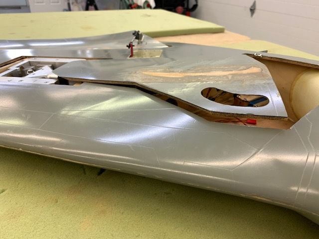
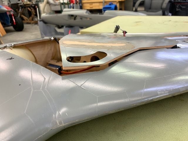
Installing inside edges of gear well openings.
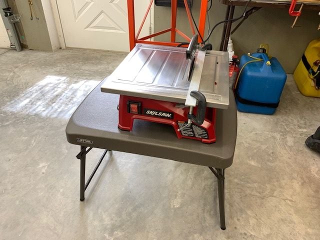
I set up my wet tile saw to cut several strips of .020 G-10 material. I found this is a good way to make several straight cuts. Doesn't tear up my jig saw blades and no dust.
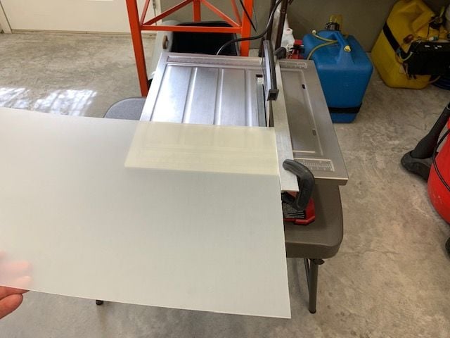
Had to make an aluminum fence because the regular fence allowed the thin material to slide under it.
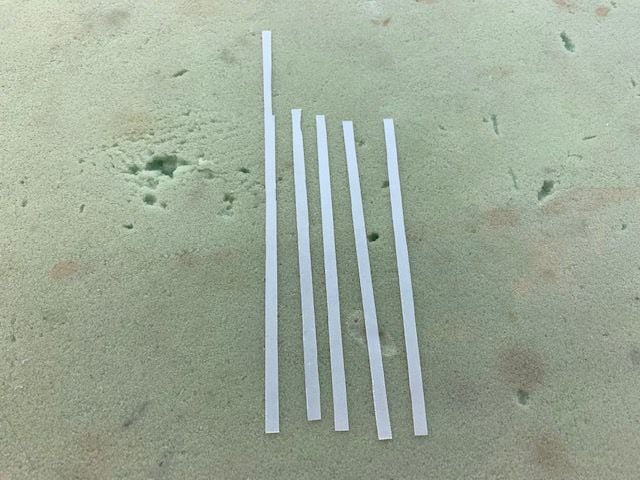
First batch. I had to cut some more to finish the job. The irregular cuts at the top were on the big piece before I started cutting.
I used thin CA to attach the strips to the edges of the gear well. I quickly learned to place a piece of clear plastic under my fingers after the first one. Bet you can't guess why!
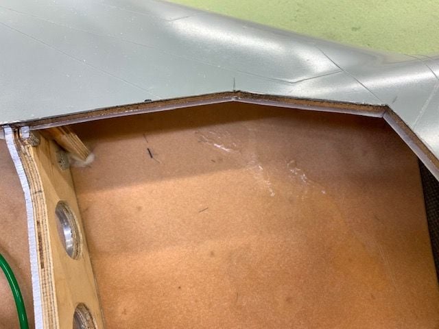
Leading edge of gear well
 .
.
Trailing edge. I went around all the strips again with thin CA and medium if there were any gaps. They are glued on really well now.
Notches cut for inner gear door hinges
Now the gear doors will lay in the wheel well and I can position the main door on the lower strut at the correct level.
I set up my wet tile saw to cut several strips of .020 G-10 material. I found this is a good way to make several straight cuts. Doesn't tear up my jig saw blades and no dust.
Had to make an aluminum fence because the regular fence allowed the thin material to slide under it.
First batch. I had to cut some more to finish the job. The irregular cuts at the top were on the big piece before I started cutting.
I used thin CA to attach the strips to the edges of the gear well. I quickly learned to place a piece of clear plastic under my fingers after the first one. Bet you can't guess why!
Leading edge of gear well
.Trailing edge. I went around all the strips again with thin CA and medium if there were any gaps. They are glued on really well now.
Notches cut for inner gear door hinges
Now the gear doors will lay in the wheel well and I can position the main door on the lower strut at the correct level.
08-28-2021, 04:34 PM
#909
Thread Starter
My Feedback: (20)
Fitting main gear doors to struts.
Try as I might, I could never get the gear position correct if the wing was upside down. Since I only get one chance to get it right I decided to place the wing right side up to install doors on the struts. Sooo...I invented a way to work on it with the gear slop hanging down as it will be in the retracted position. I bolted the spar into the wings and place them on plastic storage containers.
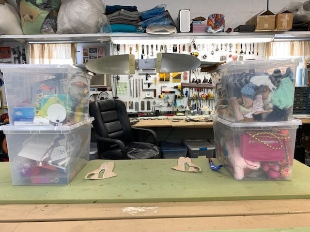
I stole the containers from my granddaughters closet so I have no idea what's in them. I put the wing on top using a foam pads and had room to work underneath.
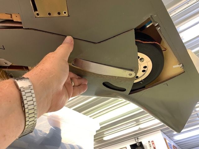
With gravity droop I could never get the doors to fit into front an back edges. I tried heating to bend them but no luck.
Finally I had to grind a slot in the back side and cut the fiberglass surface to get bend to work when heating.
It worked.
I finally got a good enough fit and taped doors in position with gear in retracted position. Right side here.
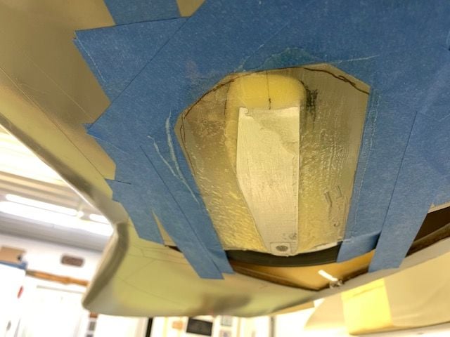
Left side ready. The plan was to inject thick epoxy into the space around the strut to get a tight fit.
I waxed the strut but did not have confidence it would release so I smeared some Vaseline on the strut. The epoxy was pushed into the edge gaps and filled in at the top of the strut. Peel ply was placed over the fill in area.
Other side done
Tape placed over peel ply to keep the surface smooth
Peel ply removed after cure
Doors have a tight fit around strut now
I used a thin piece of G-10 to cover the holes I cut last year when first trying to get the doors to fit before the new gear blocks corrected the rotation angle when in the gear well.
G-10 attached with thin CA
All done ready to mount...or so I thought!

After bending the doors to fit I found the tires were rubbing on the trailing edge of the doors. So back to the dust table to grind out the foam all the way around this time. It's always something again!
Try as I might, I could never get the gear position correct if the wing was upside down. Since I only get one chance to get it right I decided to place the wing right side up to install doors on the struts. Sooo...I invented a way to work on it with the gear slop hanging down as it will be in the retracted position. I bolted the spar into the wings and place them on plastic storage containers.
I stole the containers from my granddaughters closet so I have no idea what's in them. I put the wing on top using a foam pads and had room to work underneath.
With gravity droop I could never get the doors to fit into front an back edges. I tried heating to bend them but no luck.
Finally I had to grind a slot in the back side and cut the fiberglass surface to get bend to work when heating.
It worked.
I finally got a good enough fit and taped doors in position with gear in retracted position. Right side here.
Left side ready. The plan was to inject thick epoxy into the space around the strut to get a tight fit.
I waxed the strut but did not have confidence it would release so I smeared some Vaseline on the strut. The epoxy was pushed into the edge gaps and filled in at the top of the strut. Peel ply was placed over the fill in area.
Other side done
Tape placed over peel ply to keep the surface smooth
Peel ply removed after cure
Doors have a tight fit around strut now
I used a thin piece of G-10 to cover the holes I cut last year when first trying to get the doors to fit before the new gear blocks corrected the rotation angle when in the gear well.
G-10 attached with thin CA
All done ready to mount...or so I thought!
After bending the doors to fit I found the tires were rubbing on the trailing edge of the doors. So back to the dust table to grind out the foam all the way around this time. It's always something again!
Last edited by Viper1GJ; 08-29-2021 at 03:27 AM.
08-28-2021, 06:02 PM
#910
Thread Starter
My Feedback: (20)
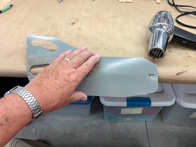
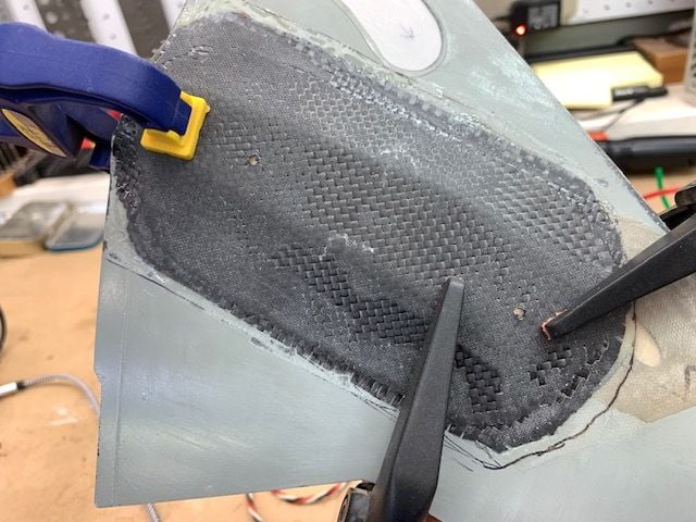
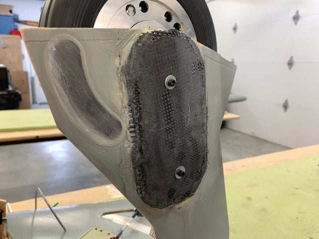
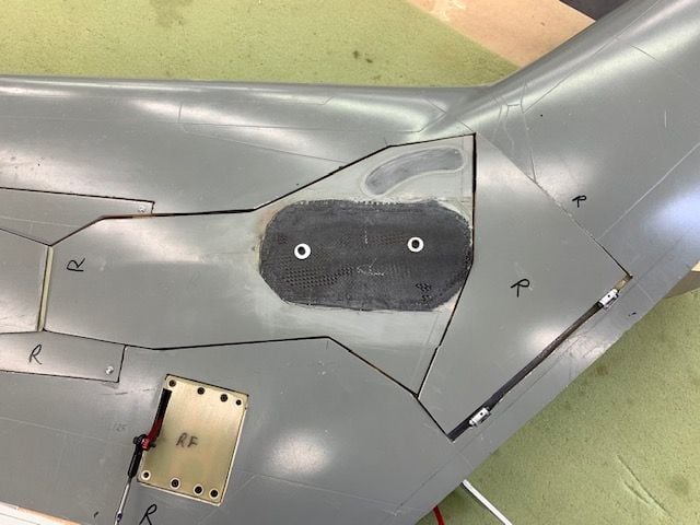
Molding carbon fiber surface on gear door
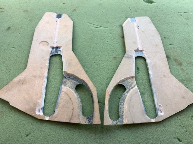
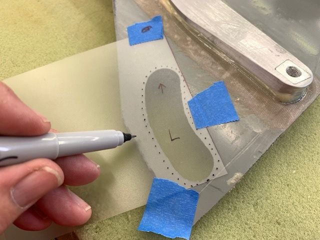
The plan is to make a double layer CF bump on the gear door over the strut that can be used to bolt the gear door to the strut. First a paper pattern was cut for the CF cloth. The second layer pattern is smaller so it will be easier to taper and fare to the edge of the gear doors
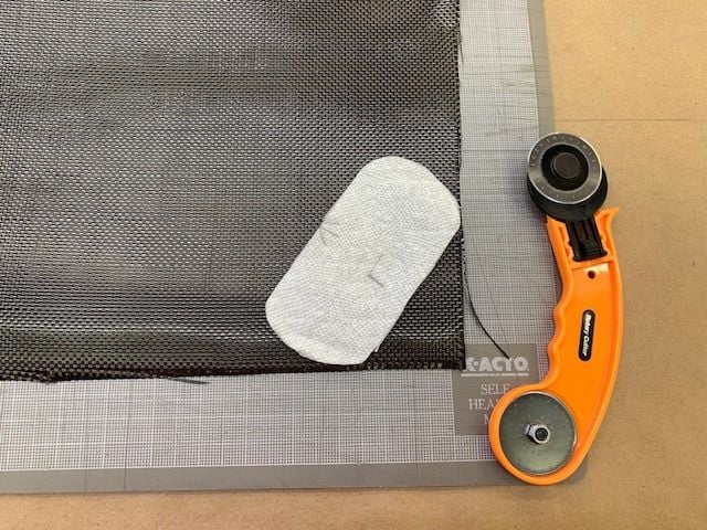
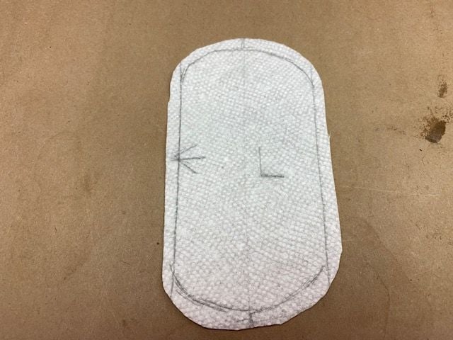
Paper pattern used to cut the CF cloth. I ran the weave of the second layer 45 degrees to the first layer. Somewhere I heard it would be stronger. IDK.
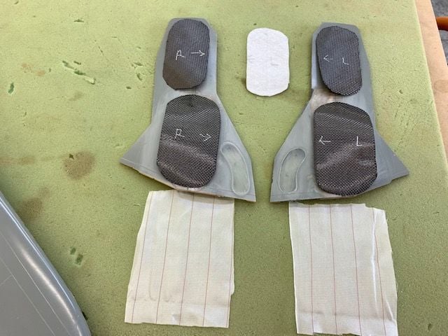
Parts cut and laid out. Peel ply was trimmed to fit after this photo
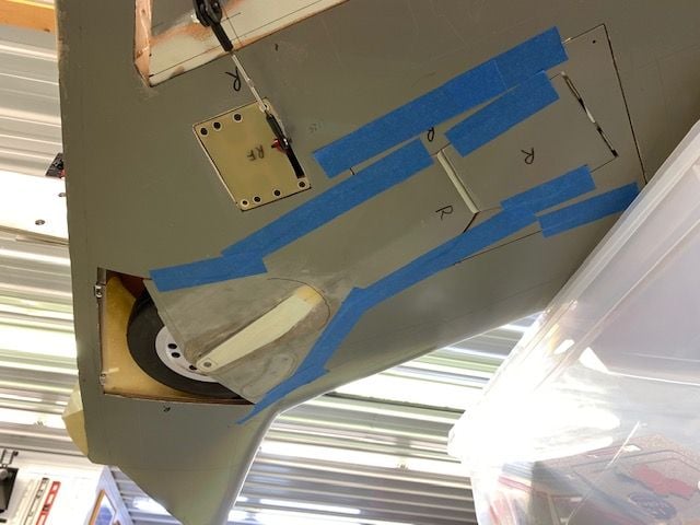
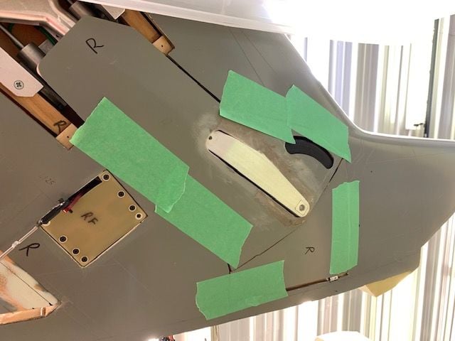
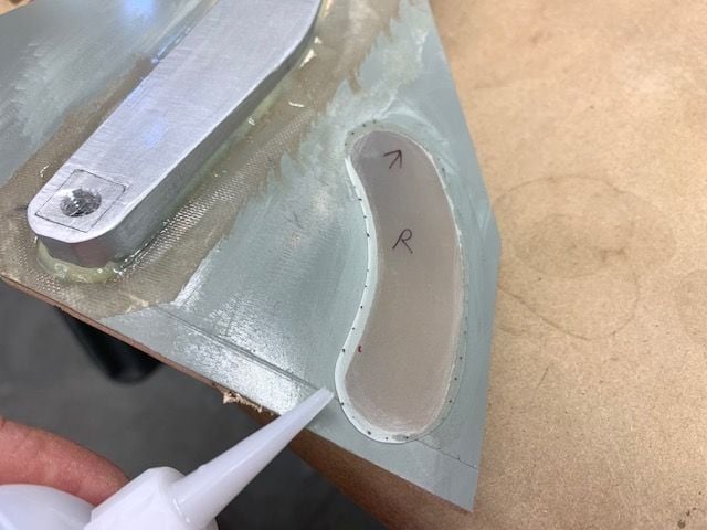
Release agent applied to struts and gear doors taped into position
Area around CF taped to keep epoxy off. I want the tape overlay to stick to the surface just outside of CF area to make the CF layers taper to the door surface.
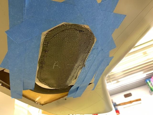
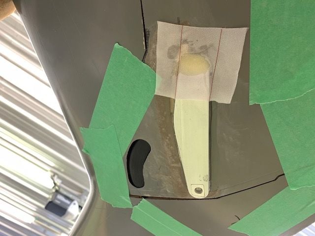
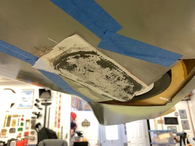
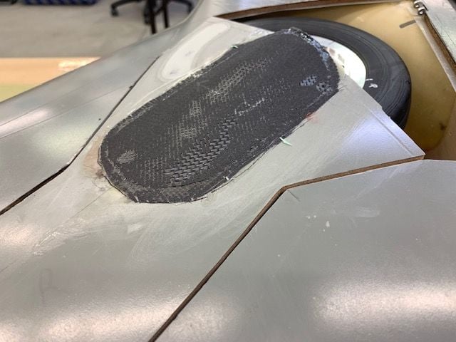
Thickened epoxy applied around strut and troweled to taper off at the edge of the blue tape. Then two layers of wetted out CF cloth applied over the strut and tapered out to the blue tape line

Blue tape removed around CF layers
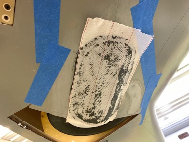
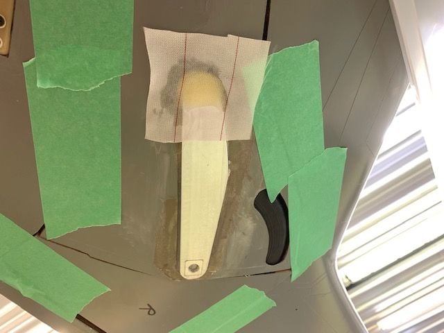
Peel ply applied over the CF cloth layers
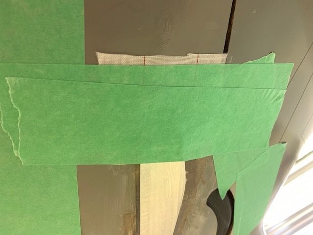
Tape applied over peel ply to keep the CF cloth tapered down to the door surface just at the CF edge.
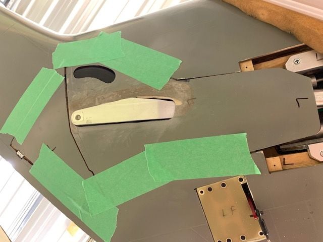
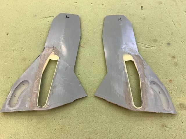
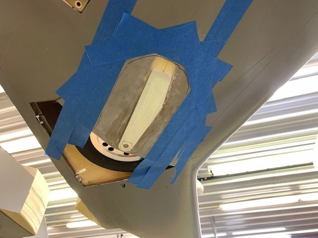
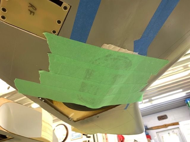
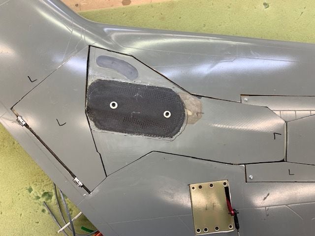
The left side now. Thickened epoxy applied around the strut and tapered out to the blue tape line
Both layers of wetted CF cloth applied, tape removed, and peel ply applied
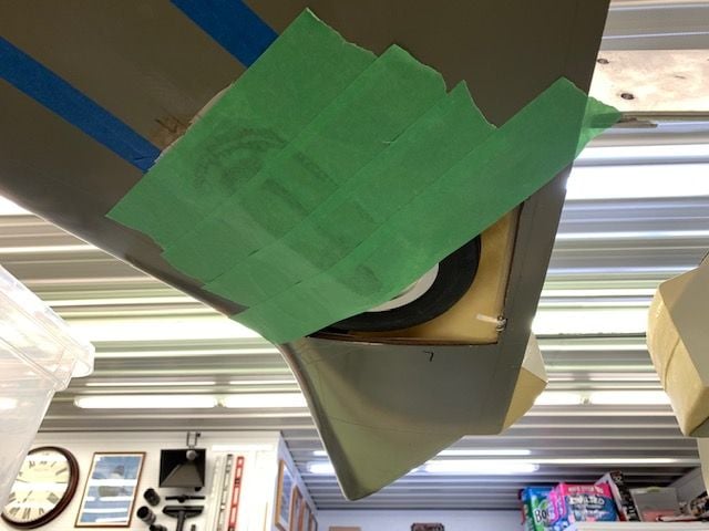
Tape over peel ply. Hopefully with a little body work the doors can be bolted on to the struts. I'm tired of messing with the landing gear.
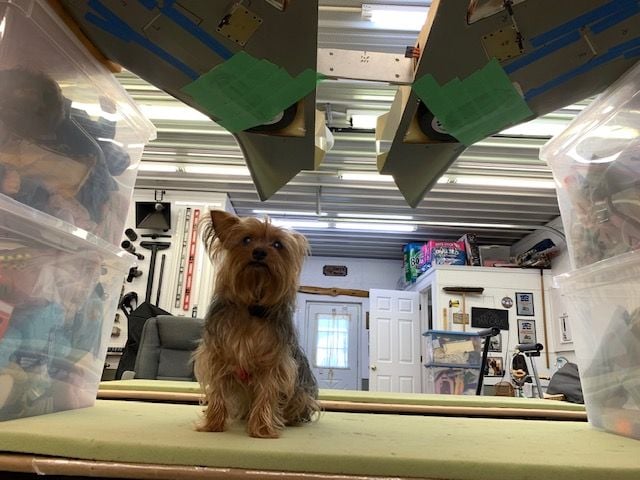
Shop supervisor says she's had enough too and time to call it a day!
The plan is to make a double layer CF bump on the gear door over the strut that can be used to bolt the gear door to the strut. First a paper pattern was cut for the CF cloth. The second layer pattern is smaller so it will be easier to taper and fare to the edge of the gear doors
Paper pattern used to cut the CF cloth. I ran the weave of the second layer 45 degrees to the first layer. Somewhere I heard it would be stronger. IDK.
Parts cut and laid out. Peel ply was trimmed to fit after this photo
Release agent applied to struts and gear doors taped into position
Area around CF taped to keep epoxy off. I want the tape overlay to stick to the surface just outside of CF area to make the CF layers taper to the door surface.
Thickened epoxy applied around strut and troweled to taper off at the edge of the blue tape. Then two layers of wetted out CF cloth applied over the strut and tapered out to the blue tape line
Blue tape removed around CF layers
Peel ply applied over the CF cloth layers
Tape applied over peel ply to keep the CF cloth tapered down to the door surface just at the CF edge.
The left side now. Thickened epoxy applied around the strut and tapered out to the blue tape line
Both layers of wetted CF cloth applied, tape removed, and peel ply applied
Tape over peel ply. Hopefully with a little body work the doors can be bolted on to the struts. I'm tired of messing with the landing gear.
Shop supervisor says she's had enough too and time to call it a day!
The following users liked this post:
jcterrettaz (08-28-2021)

The following users liked this post:
Viper1GJ (08-29-2021)

The following users liked this post:
Viper1GJ (08-29-2021)
08-29-2021, 04:43 PM
#913
Thread Starter
My Feedback: (20)
I plan to paint it as an F-105D in classic SEA scheme from the 13th Fighter Squadron which was my last operational squadron assignment in the F-16. That's if it gets that far. I'm not going to do any body work or painting till I fly it and see if it can last. I'm concerned about the main gear and gear mounts with the weight. We will see.
Thanks,
Gary
08-29-2021, 04:59 PM
#914
Thread Starter
My Feedback: (20)
Gear doors cured
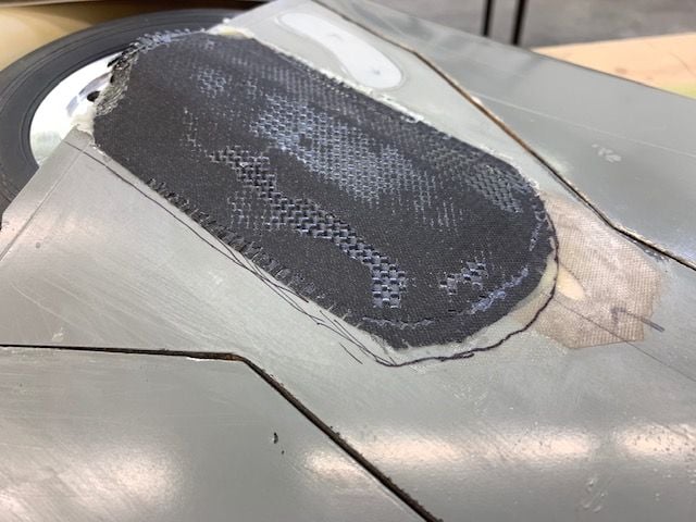
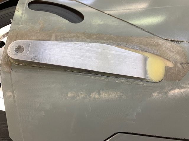
Tape and peel ply removed.
I pleased with how it came out.
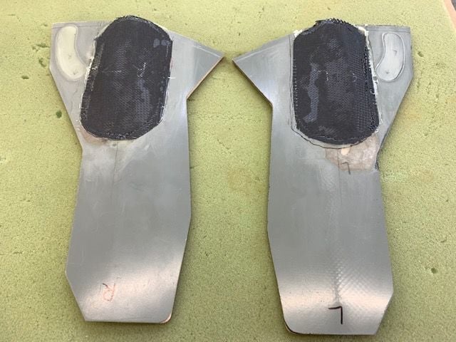
Both doors popped off the struts without a fuss
The CF will make a nice mounting surface to the lower strut.
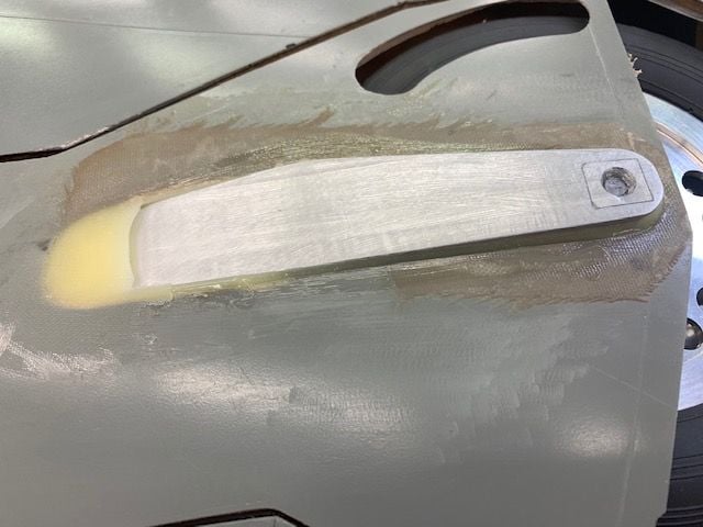
Top layer of CF tapered in well
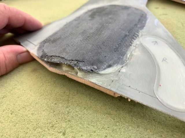
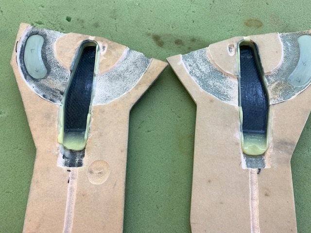
Bottom of doors will require some fill and shaping
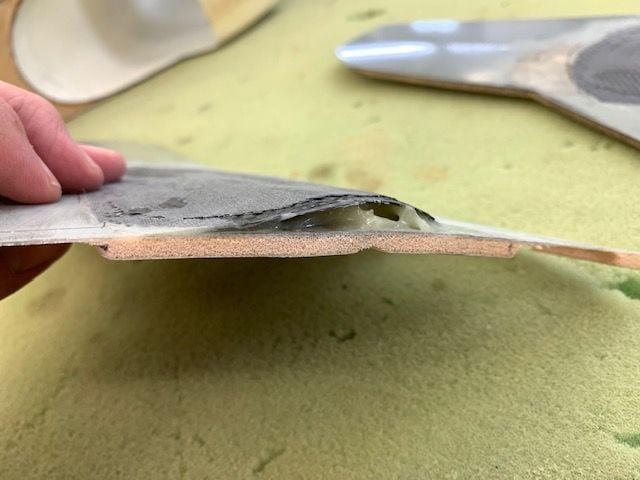
Same here
I had planned to blend the bump over to the inner door but now I will not.
I'm just going to fill and round off the bottom of the main door and keep all the body work on the main door. Much less work than blending the bump over to the inner door as I had first planned. It can't be seen when gear is down and will never be noticed at all when retracted while flying.
Tape and peel ply removed.
I pleased with how it came out.
Both doors popped off the struts without a fuss
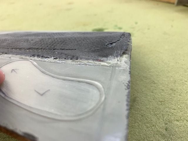
The CF will make a nice mounting surface to the lower strut.
Top layer of CF tapered in well
Bottom of doors will require some fill and shaping
Same here
I had planned to blend the bump over to the inner door but now I will not.
I'm just going to fill and round off the bottom of the main door and keep all the body work on the main door. Much less work than blending the bump over to the inner door as I had first planned. It can't be seen when gear is down and will never be noticed at all when retracted while flying.
08-29-2021, 05:13 PM
#916
Thread Starter
My Feedback: (20)
Outer gear doors final glued together and adjusted
I had only tack glued the outer door hinges and ball links on since last testing. I did final gluing of all hinges and ball link bracket. Pushrods adjusted. I glued the 3D printed door arm to the strut with goop to keep it from sliding on the lower strut.
Going...
Going...
Going...
Gone! Many thanks to my friend Keith for designing the 3D printed door arm. As I remember I gave up on it and he made it work. Thanks again Keith!
Next task is to figure a way to route the brake line and RPM sensor wire from the wheel through the gear to the wing route without pinching, cutting, or binding. There is no good way with the strut bending, rotating, and mechanics moving at the bottom. We will see...
The following 2 users liked this post by Viper1GJ:
jcterrettaz (08-30-2021),
skunkwurk (08-30-2021)
The following users liked this post:
Viper1GJ (08-30-2021)

The following users liked this post:
Viper1GJ (08-30-2021)
08-30-2021, 07:20 AM
#919
Thread Starter
My Feedback: (20)
Hi Dave,
I was 13th OpsO in 91-92 timeframe at MSJ, then OSS/CC and DOG after that. I retired from Lockheed Ft Worth Carswell in 95 doing F-16 production test and acceptance flights.
Watching your F-100 work. I envy your weathering skills. Keep posting pics.
I'm still looking for any photos of a 13th F-105 with the JE tail code. Would you have any sources?
You still flying?
Gary
08-30-2021, 07:25 AM
#920
Thread Starter
My Feedback: (20)
LOL, I'm not sure who's submitting, me or this jet. Sometimes I just want it out of the way. It's too big and heavy for me to move around now and I'm moving to smaller jets. I may let the next guy paint it.
08-30-2021, 01:14 PM
#921

My Feedback: (13)
Gary,
missed you by a few years. Those were the Block 30 days weren’t they? Neat place for sure. They were WWs when I got there
i don’t know of any of those pics but will ask some of the younger guys that just left there and see if they’ve got a book in the squadron or something with photos
I’ve been in the Gomers for the last 12 hrs or so. Getting near the end though
Thanks for the kind words on the Hun. Thankfully I’ve got a buddy smart on weathering who isn’t afraid to tell it like it is and create a better end product
ive said it many times: this Thud is lucky to have found you or it would be a static model or smoking hole. You’ve done it justice
The following users liked this post:
Viper1GJ (08-30-2021)
08-30-2021, 04:54 PM
#922
Thread Starter
My Feedback: (20)

The following users liked this post:
Viper1GJ (08-31-2021)
08-31-2021, 05:43 PM
#924
Thread Starter
My Feedback: (20)
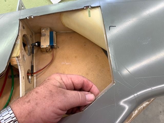
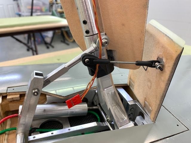
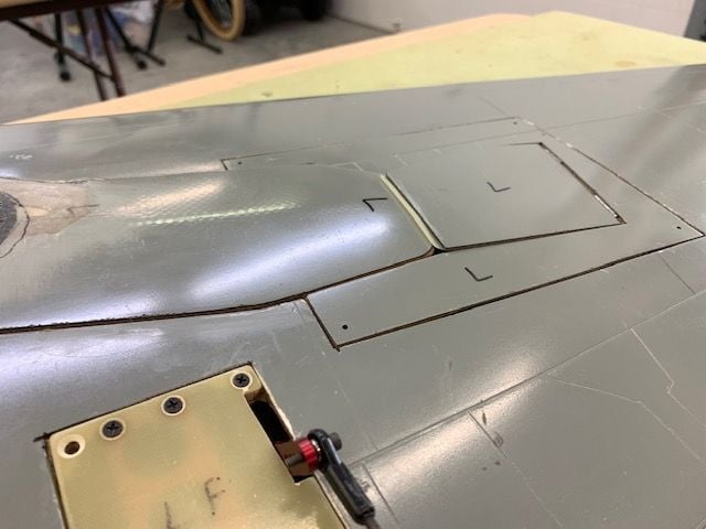
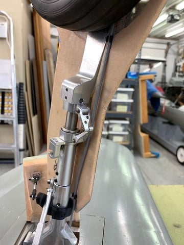
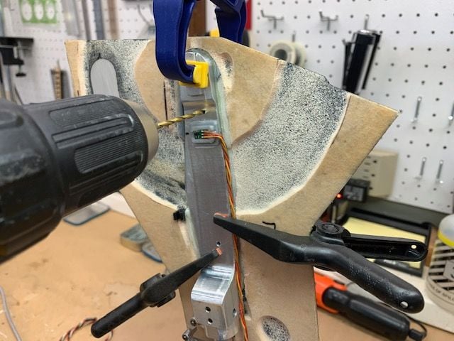
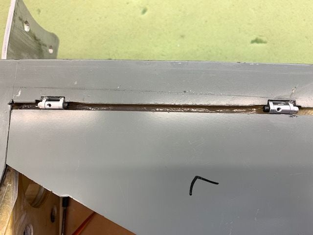
Installing brake air line and RPM wire
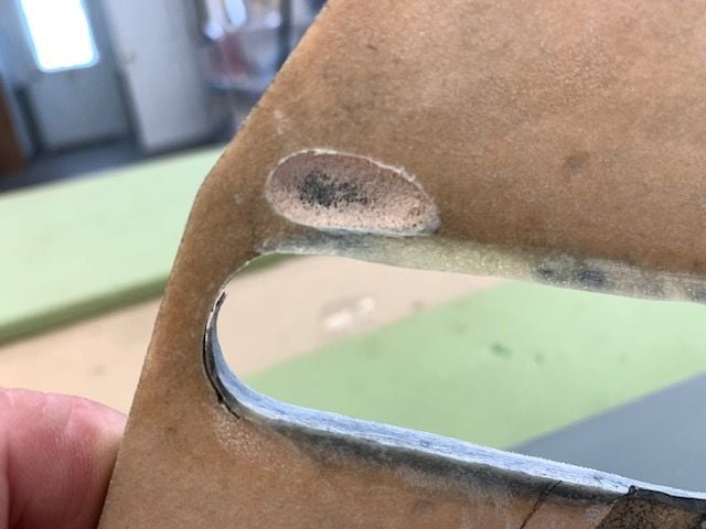
It took 2 days to figure this out. It looks simple now but there were multiple attempts to get here. Hopefully this install will work. The first problem is the close proximity of the wheel and tire to the gear door. This is caused by the need to recess the strut into the gear door and bend a curve in the door to get it to fit to the bottom of the wing. As a result there is almost no room anymore to run the brake line and RPM sensor wire without them touching the tire. Also I wanted to be able to remove the wheel, brake, and gear door for maintenance so everything needed quick disconnects.
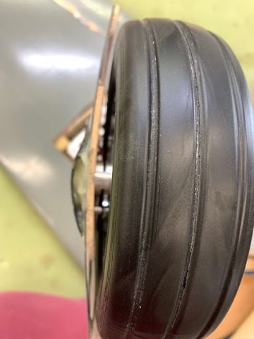
Here is the problem, no clearance.
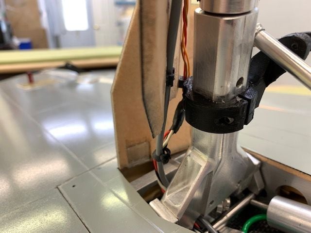
This was the final solution to the RPM sensor. WIres were Gooped to the lower strut inside edge. This is only place I could find to place them with the strut sunk into the door. The sensor will stay with the strut but allows the wheel, brake, and door to come off for maintenance.
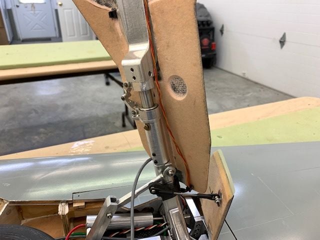
Next issue is to provide protection when the strut compresses. The wires are attached to the upper door clip and will keep them from getting pinched as the strut compresses since the door is only attached to the lower strut.
Location of wire clip was set by trial and error to keep clear of outer door arm, clear of upper strut when lower strut rotates, and clear of the rotation pin below the strut in the photo
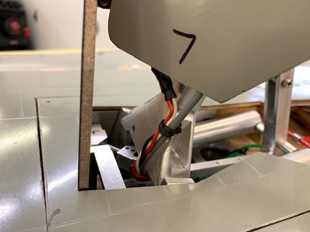
The brake air fitting now has to be recessed into the door and had to have a relief for the brake line running down in the photo. The first air clip had to be recessed to keep the air line away from the wheel.
As with the wire, the air line is attached to the door to keep it from getting pinched when strut compresses. The gear door will slide toward the wing when strut compressed because it is only attached to the lower strut.
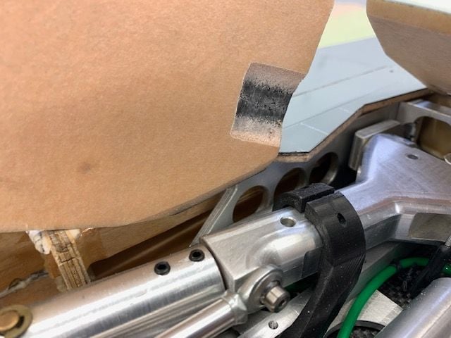
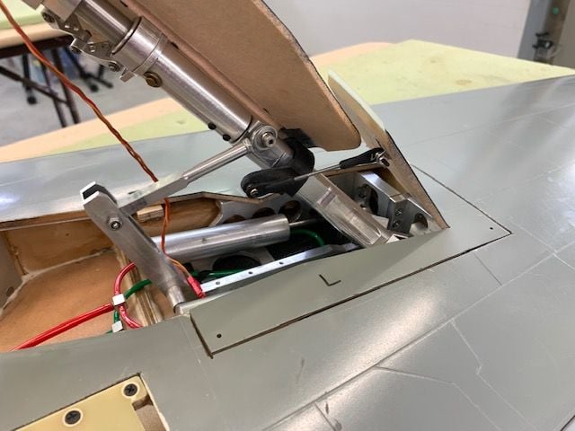
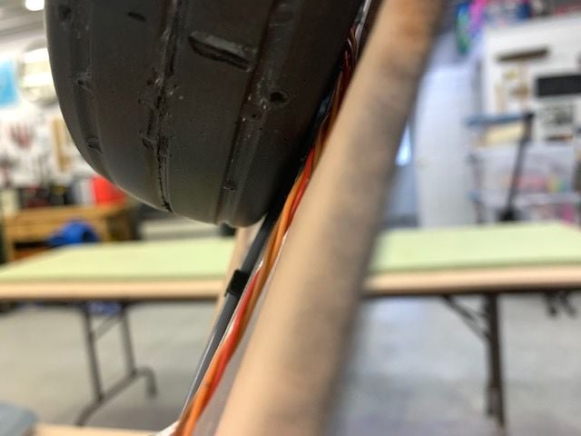
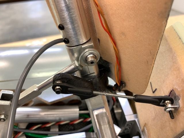
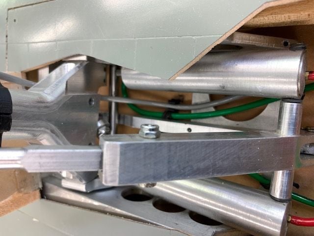
The next issue was to run the air line and wires together between the door and strut and under the hinge point of the upper strut, and stay away from all the moving metal inside the gear frame.
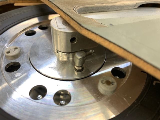
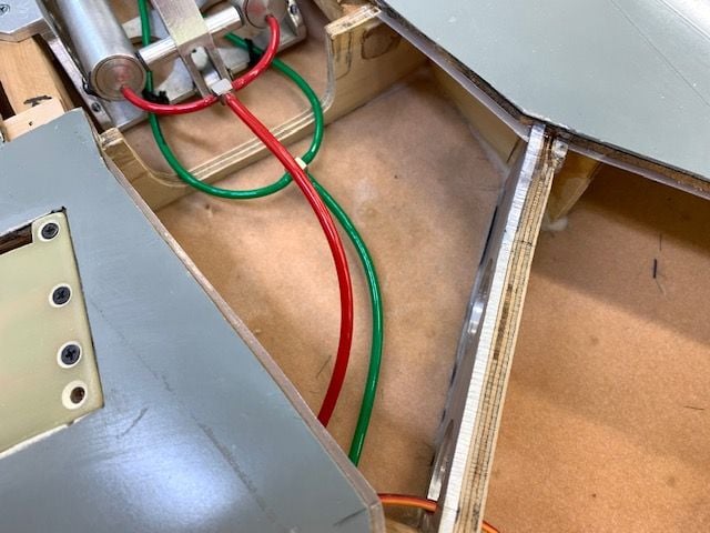
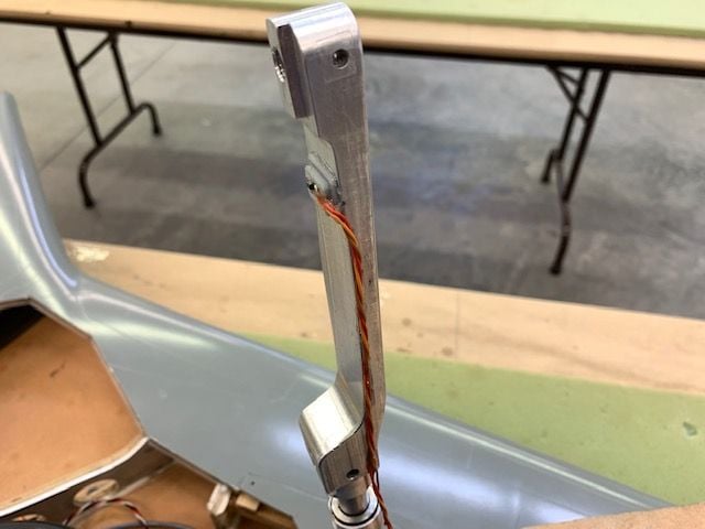
I tied them together with some waxed lacing thread to go under the forward side because the rotation pin is on the aft side as seen here.
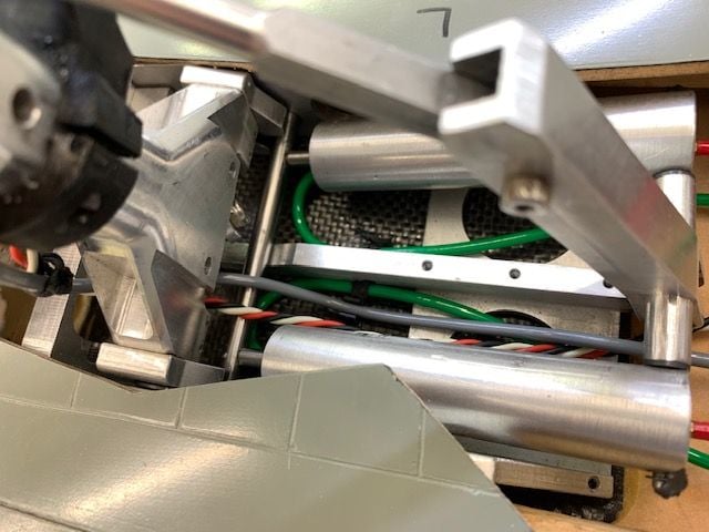
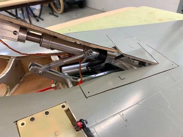
They had to go under the strut but over the slider bar to keep from getting pinched or stretched. Both lines had to be on the side away from the rotation pin to get under the gear with out getting cut. I had to use a clip on the wing skin to keep the tubing and wire from popping up and getting pinched while gear retracts and preventing the gear from locking up. Then both had to go under the outer cylinder support bar to keep them from stretching and popping out of the clip when the gear retracts. All this took a while to figure out.
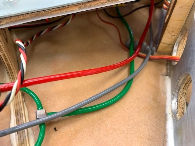
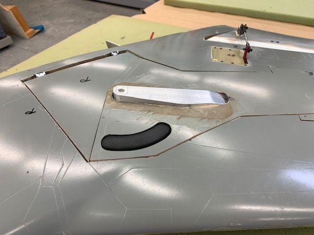
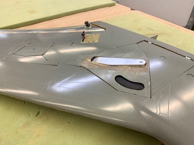
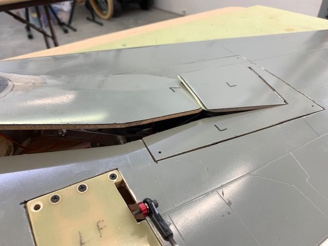
Exit out to the wing root was normal.
The left side took 2 days. The right side without the RPM sensor took only about an hour. Was a steep learning curve.
Tubing clips on wing skin here
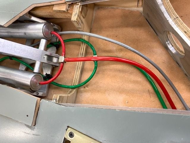
Tubes run to wing root on right side.
Next is to bolt the gear doors to the struts.
It took 2 days to figure this out. It looks simple now but there were multiple attempts to get here. Hopefully this install will work. The first problem is the close proximity of the wheel and tire to the gear door. This is caused by the need to recess the strut into the gear door and bend a curve in the door to get it to fit to the bottom of the wing. As a result there is almost no room anymore to run the brake line and RPM sensor wire without them touching the tire. Also I wanted to be able to remove the wheel, brake, and gear door for maintenance so everything needed quick disconnects.
Here is the problem, no clearance.
This was the final solution to the RPM sensor. WIres were Gooped to the lower strut inside edge. This is only place I could find to place them with the strut sunk into the door. The sensor will stay with the strut but allows the wheel, brake, and door to come off for maintenance.
Next issue is to provide protection when the strut compresses. The wires are attached to the upper door clip and will keep them from getting pinched as the strut compresses since the door is only attached to the lower strut.
Location of wire clip was set by trial and error to keep clear of outer door arm, clear of upper strut when lower strut rotates, and clear of the rotation pin below the strut in the photo
The brake air fitting now has to be recessed into the door and had to have a relief for the brake line running down in the photo. The first air clip had to be recessed to keep the air line away from the wheel.
As with the wire, the air line is attached to the door to keep it from getting pinched when strut compresses. The gear door will slide toward the wing when strut compressed because it is only attached to the lower strut.
The next issue was to run the air line and wires together between the door and strut and under the hinge point of the upper strut, and stay away from all the moving metal inside the gear frame.
I tied them together with some waxed lacing thread to go under the forward side because the rotation pin is on the aft side as seen here.
They had to go under the strut but over the slider bar to keep from getting pinched or stretched. Both lines had to be on the side away from the rotation pin to get under the gear with out getting cut. I had to use a clip on the wing skin to keep the tubing and wire from popping up and getting pinched while gear retracts and preventing the gear from locking up. Then both had to go under the outer cylinder support bar to keep them from stretching and popping out of the clip when the gear retracts. All this took a while to figure out.
Exit out to the wing root was normal.
The left side took 2 days. The right side without the RPM sensor took only about an hour. Was a steep learning curve.
Tubing clips on wing skin here
Tubes run to wing root on right side.
Next is to bolt the gear doors to the struts.
The following users liked this post:
grbaker (09-01-2021)
09-01-2021, 03:30 PM
#925
Thread Starter
My Feedback: (20)
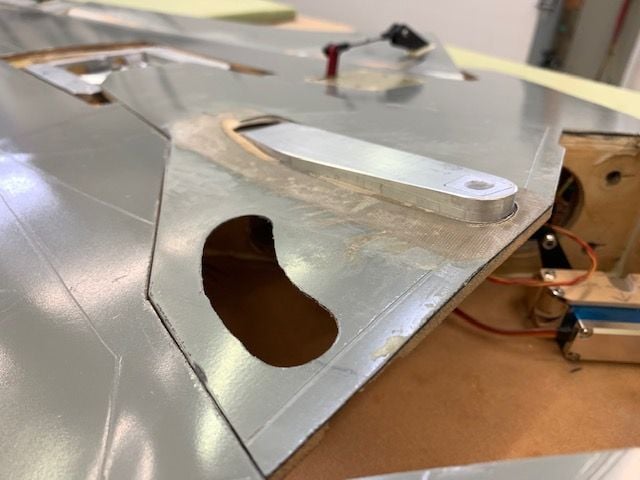
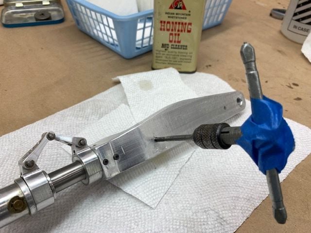
Installing gear doors
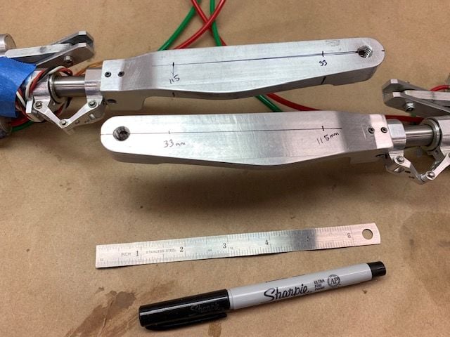
Struts were marked for drill locations. The 33mm spot was to clear the RPM sensor on the other side. The 115mm was TLAR.
Marked locations center punched
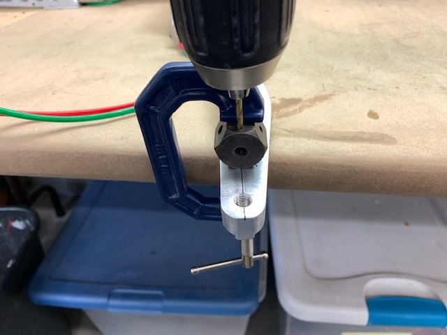
Drill jig used to keep it near straight.
Holes drilled with #36 drill for 6-32 tap
After holes drilled in lower strut the door was clamped on and back drilled for screw hole
Screw holes in CF door skin
Threads tapped with 6-32 tap using some cutting oil
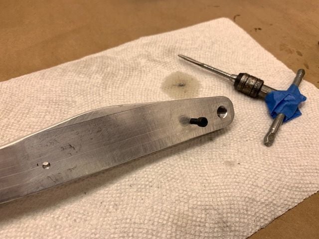
Threads tested with 6-32 bolt
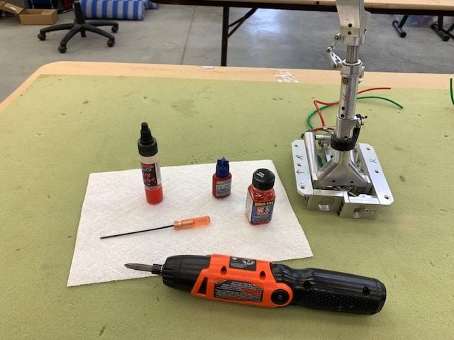
Next step is wings final assembly. I went through each gear with VibTite, Blue Locktite and silicon lube on moving parts. Kind of a final check before mounting and testing. I'm counting on the cone point set screws with blue Locktite to keep the lower strut in alignment.
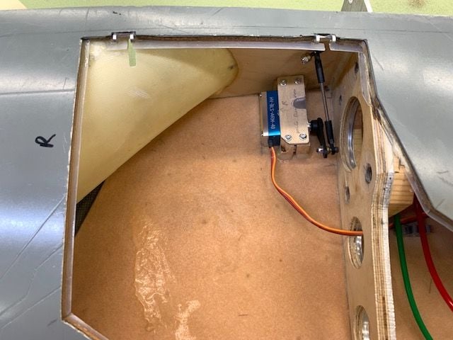
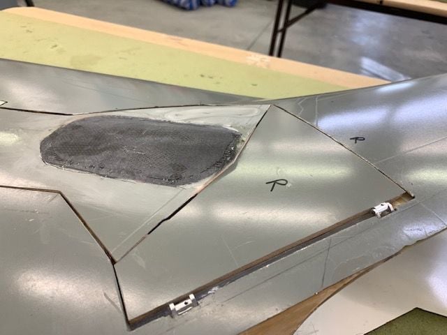
Inner gear doors installed and nuts put on hinge bolts. This means I'm not planning on removing them anytime soon!
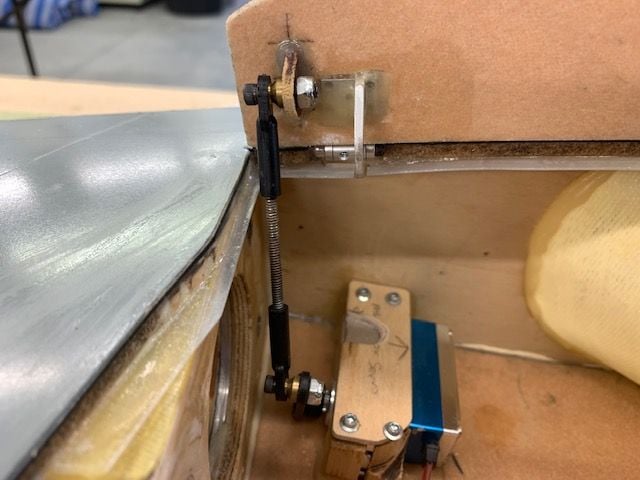
Inner door servo pushrod attached.
Gear doors finally installed. They went on perfectly. This felt like a major milestone for me. The gear and doors have been a major PIA since the start. I felt I finally turned a corner toward the final stretch. Yea!
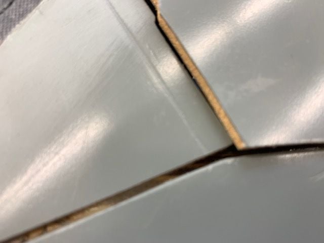
After all the cutting, fitting, and testing, the right inner door hit the main door on the lower corner. How does that happen???
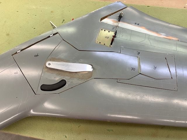
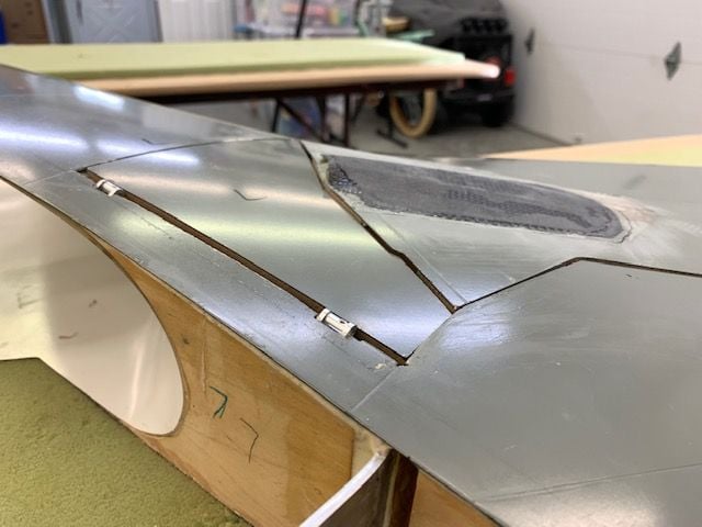
It was an easy fix with a permagrit sanding tool. Works good now.
Left side fit right in. I'll finish final wing assembly next and then move to the cockpit and canopy.
Struts were marked for drill locations. The 33mm spot was to clear the RPM sensor on the other side. The 115mm was TLAR.
Marked locations center punched
Drill jig used to keep it near straight.
Holes drilled with #36 drill for 6-32 tap
After holes drilled in lower strut the door was clamped on and back drilled for screw hole
Screw holes in CF door skin
Threads tapped with 6-32 tap using some cutting oil
Threads tested with 6-32 bolt
Next step is wings final assembly. I went through each gear with VibTite, Blue Locktite and silicon lube on moving parts. Kind of a final check before mounting and testing. I'm counting on the cone point set screws with blue Locktite to keep the lower strut in alignment.
Inner gear doors installed and nuts put on hinge bolts. This means I'm not planning on removing them anytime soon!
Inner door servo pushrod attached.
Gear doors finally installed. They went on perfectly. This felt like a major milestone for me. The gear and doors have been a major PIA since the start. I felt I finally turned a corner toward the final stretch. Yea!
After all the cutting, fitting, and testing, the right inner door hit the main door on the lower corner. How does that happen???
It was an easy fix with a permagrit sanding tool. Works good now.
Left side fit right in. I'll finish final wing assembly next and then move to the cockpit and canopy.
The following 4 users liked this post by Viper1GJ: