


1/6 F-105 Build Thread
 02-02-2021, 07:11 PM
#851

Hi Gary, big fan of this build please don't lose faith now you have come so far!! Anyways, if it's not too hard could you switch air cylinders and see if the problem persists? That way you could rule out them and know it's something in the linkage...maybe a piece of crap or restriction in an airline or the lazy cylinder. Maybe a burr in the linkage slot? The video makes the cylinders look misaligned but I doubt they are. Hope it's something that simple. Awesome thread!!

 02-02-2021, 08:32 PM
#853

Gary,
i was having a similar issue with the gear on my big 40% Cessna 310. I found that the ramp for the uplock was a little gritty and a little too tight on the retraction slider bar. I cleaned up the corners of the side plates with a file to put a sligjt chamfer on the inside surfaces and then polished the riding surfaces on the side plates a dremel and some metal polish. That helped immensely in smoothing them out.
as for the slamming down, i would recommend one of these on each up line:
Tailonz Pneumatic SCF-5/32 Air Flow Control Valve with Push-to-Connect Fitting, in-Line Speed Controller Union Straight - 5/32 Inch Tube OD x 5/32 Inch Tube OD (Pack of 5)
they are setup so they provide a restriction with flow in one direction and no restriction for flow in the opposite direction.
that will allow you to slow down the air leaving the cylinders when going down (you restrict the up line airflow) while getting full slow when going up.
as for them not making its way up. I would recommend one of the hi-flow retract valves. I designed and 3D printed my own and its amazing how much of a difference a valve designed for hi-flow works compared to one with just bigger festo fittings.

The following users liked this post:
patf (02-03-2021)
02-03-2021, 12:17 AM
#855

Gary,
My day job is running a company that builds bespoke hydraulic and pneumatic machinery. I can tell you that the biggest challenge in this industry is trying to synchronise multiple actuators (Hydraulic or pneumatic) connected you the same piece of equipment. The problem is that even tiny differences in friction, either in the cylinders or in the mechanism will cause one cylinder to move first. If the linkage is not stiff enough the differential movement one side to the other exacerbated the differential friction and the whole lot locks up. In hydraulic systems there are various types of flow dividing valves that try to equalise the flow to both cylinders and sometimes these will work but they are not 100% accurate and so small differential movements can still cause jamming. This type of flow control won’t work on pneumatic systems because of the compressibility of the fluid. The only way you are going to get this to work is if the mechanism can be made stiff enough to keep the cylinders synchronised. So in your case this means the cross bar has to be guided in some way that it can’t tilt with respect to the gear side plates. To prove what I’m saying you could disconnect the cylinders and see if you can twist the cross bar and get it to jam. I’m sure you will be able to. Difficult to see how you could stop it twisting, maybe large flanges that run inside the gear plates but then they would need to be much larger to provide the clearance for the flange. I think the best solution would be one much larger cylinder, centrally mounted to the cross bar. It would need to have a large enough rod to provide stiffness at the connection to the cross bar.
As I said, this type of problem is the most difficult fluid power issue that I have faced in over 40 years in this industry! Sorry I can’t be more positive!
Malcolm
02-03-2021, 04:02 AM
#856

Hi Gary,
If Malcolm is correct (and his day job experience suggests to me he probably is) then you may be faced with modifications to the gear that require machining new parts .. e.g. replacing the two cylinders with a single larger one as he suggests. If you have to go to this much trouble, the other thing you could consider is is changing from pneumatic to electric actuators .. even with two actuators, the electric ones would be able to travel together with very good synchronization. I've done some air to electric conversions and would be happy to discuss with you sometime by phone if you like.
It always amazes me how much excellent advice is available here from our fellow modelers around the world .. so maybe an even simpler approach will be suggested!
Dave
02-03-2021, 05:00 AM
#857
Yes, Dave’s suggestion is a good one.
In my day job I always tell people if there is a way to keep hydraulics and pneumatics out of their machinwry they should take it! They are usually amazed at this advice given its how I earn my living, but I’ve learned it’s horses for courses!
Malcolm
In my day job I always tell people if there is a way to keep hydraulics and pneumatics out of their machinwry they should take it! They are usually amazed at this advice given its how I earn my living, but I’ve learned it’s horses for courses!
Malcolm
02-03-2021, 08:14 AM
#858
Gary .. one other probably stupid thought . As the pressure starts to change, it does not do so instantly .. it takes a little air flow to develop a significant force -- I bet it makes the "which one starts faster due to friction" problem worse.
I wonder if you put a spring on each side of the connecting bar, working in parallel with the cylinders -- pulling "back" (to the left in your picture) so that it was stretched in the up position .. as soon as the pressure drops the spring force will dominate the initial air pressure's force since that will build slowly ... but the spring force is instantaneous. If you have some springs lying around you might be able to do it without any disassembly or drilling. Or get some springs from McMasterCarr .. they have every type known to man...
I don't think this really solves the fundamental issue as discussed just above here .. but might be worth a try to help troubleshoot.
Dave
02-03-2021, 12:42 PM
#859

The other thing I would look at is maybe introducing some "controlled" slop in that system, but I would not know where to do it. That would let the compliance happen at a known point and then you can manage it better. When everyhting is tight it is hard to know where to start.
You are an inspiring master builder Gary. Worst case walk away from it, you know the drill
02-03-2021, 02:53 PM
#861
Thread Starter
My Feedback: (20)
Wow!
Thanks for all the really great comments. I read every one and got some great ideas. Amazing amount of expertise and knowledge is here in the forums. I learn stuff all time. The good news is the nose gear is fixed because of the comments. The bad news is the gear valve is not working and I am asking for more help.
Thanks,
Gary
 02-03-2021, 03:48 PM
#863
Thread Starter
My Feedback: (20)
Good News Bad News
Good new first. The nose gear is fixed and now works 100% of the time with no issues. I don't know what was causing the binding but the fix was pretty easy after I read Thomas's comments. I took the gear out and started looking at how it worked and thought that the up lock slot angle may be too sharp to pull the slide bar back over.
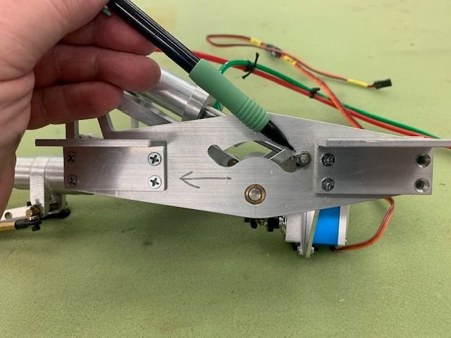
The air cylinder had to pull the slide bar left and down out of the up lock slot. I thought if I reduced this angle slightly maybe it would allow the left side of the slide bar to slide down easier.
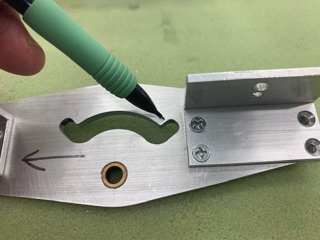
I took the side off and looked at the top of the up lock slot here and figured I could file some material off the top side
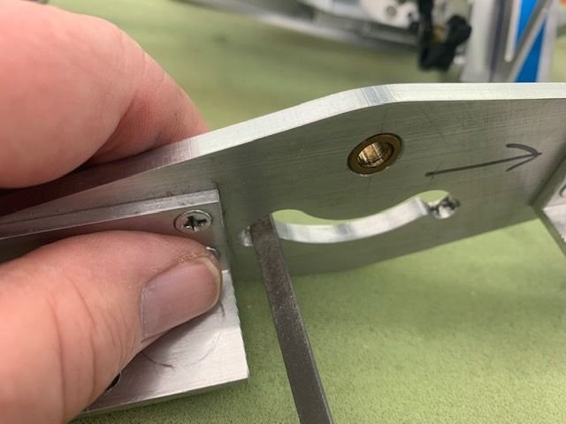
I used a jeweler's file to slowly remove some material off the slot to reduce the angle.
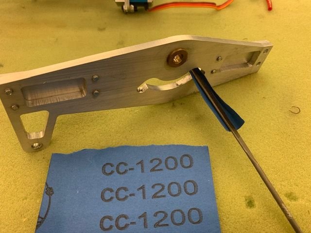
I then smoothed the slot with 1200 grit paper which is the finest I had. I reassembled and re installed and it worked perfect the first time. And the next 25 times! I also found a flow restrictor like the one Thomas recommended. (I got some of those last year when I first tested the main gears.) Now the nose gear works perfect with the two cylinders. I'd rather be lucky than good any day!
Now the bad news. The valve quit.
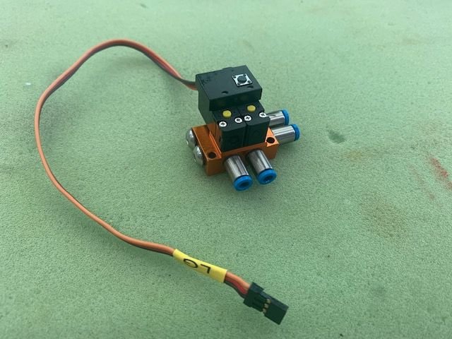
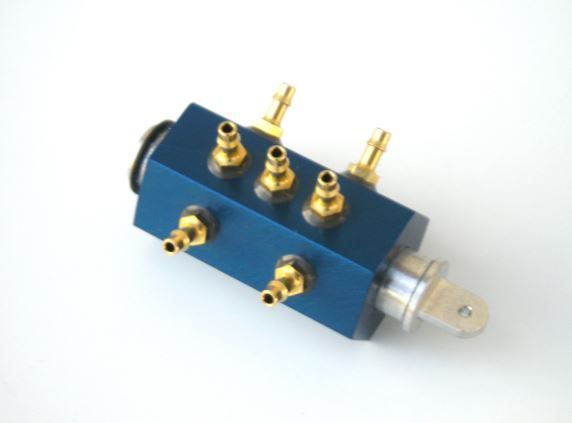
After I was satisfied the nose gear was working ok I connected the mains and began to test all three together. I did 4-5 swings. The down extension was good and needed the flow restrictors to soften the lock in the down position. The up retraction was slow but the mains did tuck in the wheel well and lock, but just barely. I added the restrictor valves to the mains and got 2 swings when I heard air hissing and nothing would work anymore. What I found out was the valve was loosing air out the vent port. Nothing I did could stop it. Cycle power, cycle up to down and back, reprogramming button, plugging the port, nothing would get it working again. It seems like the one of the valves is stuck half open and allows air to escape.
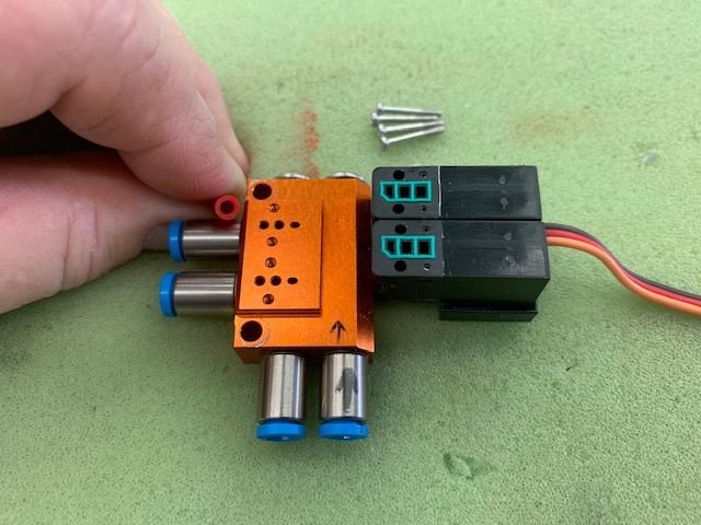
I took the valve out and unscrewed the valve blocks from the manifold block. I could not see anything moving inside the valves at all. However what I did notice was the size of the holes in the manifold block. Tiny!. I compared the 4mm tube and it is much bigger. I reassembled the valve and tried again. No luck.
I finally gave up and took the valve apart again to figure out how it was supposed to work. I took the tube connections off to get a better look inside the manifold. What I found was tiny holes. Like pin holes! I thought this was a high flow valve but it is not. It just has big connections.
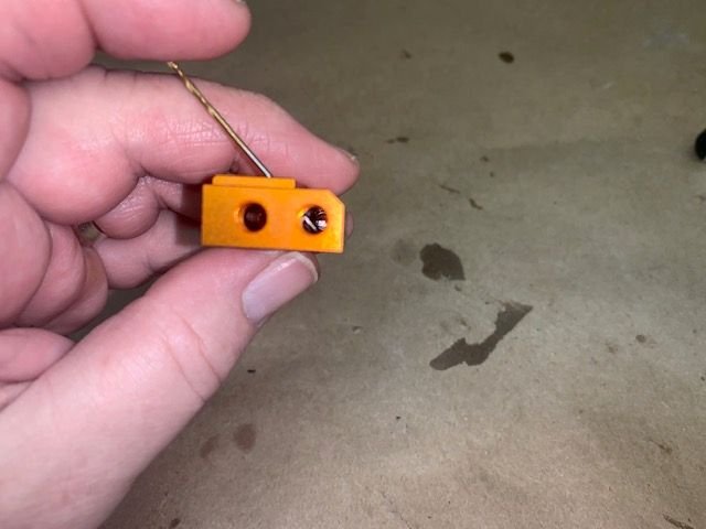
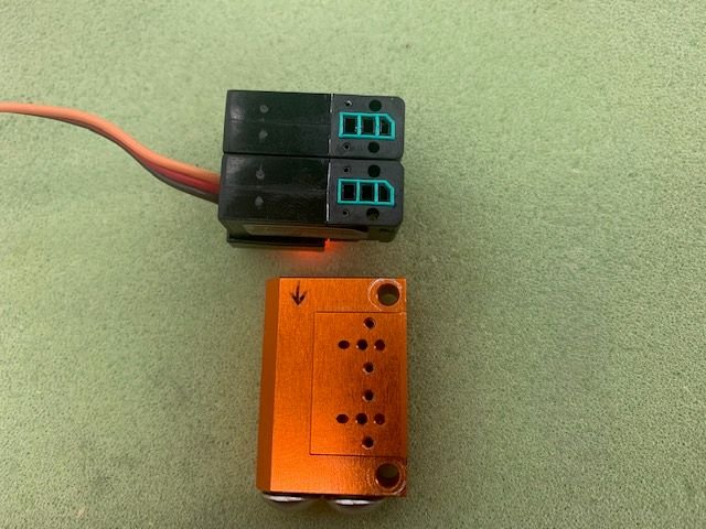
The hole on the right is the inlet. The air goes in and then up through the slanted hole. It is a #56 bit. Very small for the total air to the valve. I'm sure this is the reason the gear are slow when retracting. Not enough flow.
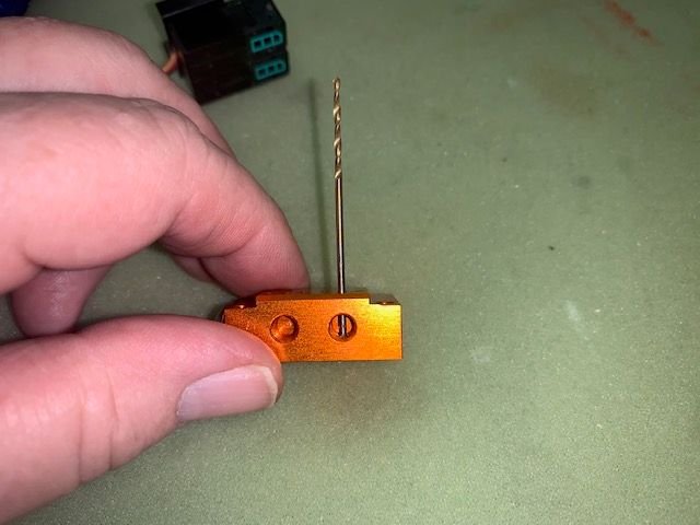
The air outlet hole to the connector is a #54 bit slightly larger than the inlet hole but still tiny. This then gets spit 3 ways to each gear. Again, too small to feed all 6 cylinders at the same time. So even if the valve was working correctly, I think it will never work well for size of the total system with 6 big cylinders lifting heavy gear struts and wheels.
The question is what next. The only other valve I know of is the JMP Hex valve with 6 outlets. Not sure if it would be big enough or not.
Suggestions welcome again.
Thanks,
Gary
Bad NewsGood new first. The nose gear is fixed and now works 100% of the time with no issues. I don't know what was causing the binding but the fix was pretty easy after I read Thomas's comments. I took the gear out and started looking at how it worked and thought that the up lock slot angle may be too sharp to pull the slide bar back over.
The air cylinder had to pull the slide bar left and down out of the up lock slot. I thought if I reduced this angle slightly maybe it would allow the left side of the slide bar to slide down easier.
I took the side off and looked at the top of the up lock slot here and figured I could file some material off the top side
I used a jeweler's file to slowly remove some material off the slot to reduce the angle.
I then smoothed the slot with 1200 grit paper which is the finest I had. I reassembled and re installed and it worked perfect the first time. And the next 25 times! I also found a flow restrictor like the one Thomas recommended. (I got some of those last year when I first tested the main gears.) Now the nose gear works perfect with the two cylinders. I'd rather be lucky than good any day!
Now the bad news. The valve quit.
After I was satisfied the nose gear was working ok I connected the mains and began to test all three together. I did 4-5 swings. The down extension was good and needed the flow restrictors to soften the lock in the down position. The up retraction was slow but the mains did tuck in the wheel well and lock, but just barely. I added the restrictor valves to the mains and got 2 swings when I heard air hissing and nothing would work anymore. What I found out was the valve was loosing air out the vent port. Nothing I did could stop it. Cycle power, cycle up to down and back, reprogramming button, plugging the port, nothing would get it working again. It seems like the one of the valves is stuck half open and allows air to escape.
I took the valve out and unscrewed the valve blocks from the manifold block. I could not see anything moving inside the valves at all. However what I did notice was the size of the holes in the manifold block. Tiny!. I compared the 4mm tube and it is much bigger. I reassembled the valve and tried again. No luck.
I finally gave up and took the valve apart again to figure out how it was supposed to work. I took the tube connections off to get a better look inside the manifold. What I found was tiny holes. Like pin holes! I thought this was a high flow valve but it is not. It just has big connections.
The hole on the right is the inlet. The air goes in and then up through the slanted hole. It is a #56 bit. Very small for the total air to the valve. I'm sure this is the reason the gear are slow when retracting. Not enough flow.
The air outlet hole to the connector is a #54 bit slightly larger than the inlet hole but still tiny. This then gets spit 3 ways to each gear. Again, too small to feed all 6 cylinders at the same time. So even if the valve was working correctly, I think it will never work well for size of the total system with 6 big cylinders lifting heavy gear struts and wheels.
The question is what next. The only other valve I know of is the JMP Hex valve with 6 outlets. Not sure if it would be big enough or not.
Suggestions welcome again.
Thanks,
Gary
Last edited by Viper1GJ; 02-03-2021 at 03:52 PM.
02-03-2021, 03:51 PM
#864
Hi Gary,
ive just looked at the pics and video again and there may be a relatively simple fix.
As I said previously, the only way this is going to work is if the structure is stiff enough to synchronise the two cylinders. No amount of playing around with balancing pipes is going to do it. It seems from the pics that the cross bar is free to rotate in the cylinder eye end connections. This implies there is clearance there, no matter how small, which allows the cross bar to move angularly so it isn’t at right angles to the rods causing the jam. If there is enough metal in those rod eyes you could drill and tap for a small grub screw to lock the cross bar to the rods. If not enough metal you might be able to clean the parts and glue with something like a Loctite high strength retaining compound. Worse case machine up a couple of rod ends with enough metal to drill and tap for grub screws.
i think this would be worth trying before re-engineering the whole system.
Malcolm
02-03-2021, 03:58 PM
#865
Hi again,
Looks like your post came as I was writing mine!
Glad you got it working but I still don’t think this is a reliable fix as the slightest bit of friction caused by debris or lack of lube in those slots is going to cause a hang up one time.
i highly recommend you look at removing the play in the cross bar!
Malcolm
02-03-2021, 05:29 PM
#866
Thread Starter
My Feedback: (20)
Malcolm, you are probably right. I thought about any twisting or flexing of the mounts or gear frame could cause a bind also. Problem is for me I don't have any machining capability, only what I can do with hand tools. But for now at least its working on the table.
Thanks,
Gary
Thanks,
Gary
 02-03-2021, 06:18 PM
#868
Thread Starter
My Feedback: (20)
Thomas, thanks for the tips. Where would us mere mortal modelers find a 3D printed valve designed for hi-flow unlike mine that just had bigger festo fittings? Seriously did you print a plastic valve? I just got a 3D printer for Christmas. Is it something a beginner could download and print?
 02-04-2021, 12:56 AM
#870
Gary,
I hear you re no machining facilities. Please have a look at this Loctite product which you could use on the bore of the rod ends to cross bar interface. Its is a very high strength retaining compound and I think it would provide the rigidity at these points you need. The only thing to watch is it does have a finite cure time and you need to allow it to fully cure before moving the joint.
LOCTITE 638 - Retaining Compound - Henkel Adhesives (henkel-adhesives.com)
Malcolm
02-04-2021, 06:11 AM
#871
Thread Starter
My Feedback: (20)
Hi Malcolm,
Thanks again for your recommendations. I think that would add some stiffness to the rod end joints and it is certainly something I can do. Getting the rod ends stiff and solid will stop small shifts in position and make the slider rod more likely to stay in position. Great Idea. I will have to order some and get it in the joints there. How long do you have to let it cure before moving the joint?
Thanks,
Gary
02-04-2021, 06:46 AM
#872
Hi Gary,
The cure time depends on the gap size as it’s an anaerobic reaction. I would follow the instructions with the product but from memory it’s typically overnight.
Regards,
Malcolm
The cure time depends on the gap size as it’s an anaerobic reaction. I would follow the instructions with the product but from memory it’s typically overnight.
Regards,
Malcolm
02-04-2021, 08:32 AM
#873
Gary, I have one of those JMP valves .. I can send it down if u want to try it .. email me.. I got if for a 1/7 scale F-15E project but ended up replacing air with hydraulic .. but that's another story..!
Dave
Dave
Last edited by ww2birds; 02-04-2021 at 08:34 AM.
02-04-2021, 09:16 AM
#874
Thomas, thanks for the tips. Where would us mere mortal modelers find a 3D printed valve designed for hi-flow unlike mine that just had bigger festo fittings? Seriously did you print a plastic valve? I just got a 3D printer for Christmas. Is it something a beginner could download and print?
I did 3D print one on my SLA machine. I responded to your PM with specifics.
02-04-2021, 09:58 AM
#875
Thread Starter
My Feedback: (20)
I talked to Tom Cook at JMP this morning and ordered a 6 output hex valve with 4mm outlets. I will test that before making more changes. Working on balancing the wheels today. Thanks for all the replies. Dave I may talk to you about the hydraulics if I give up on the air.
Gary
Gary
Last edited by Viper1GJ; 02-04-2021 at 11:00 AM.