


1/6 F-105 Build Thread


 01-20-2021, 06:18 PM
#829

Thread Starter
My Feedback: (20)
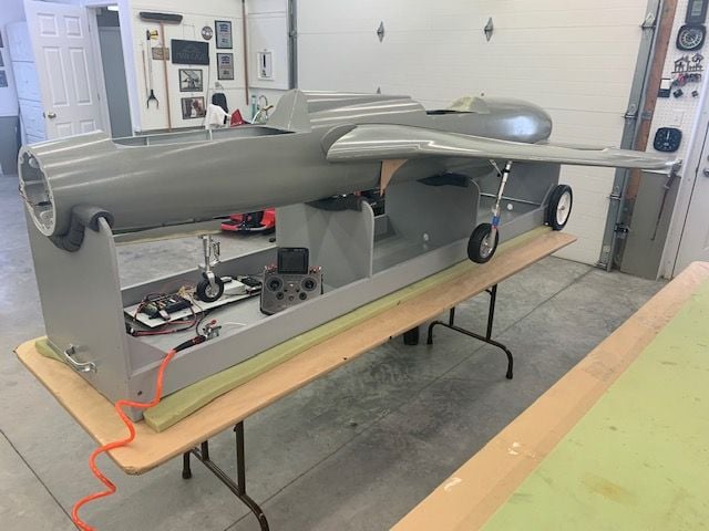
Reassembly begins after painting!
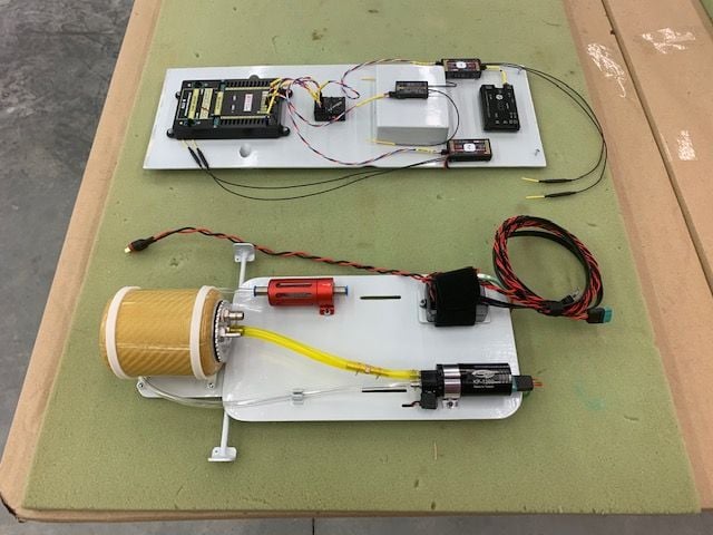
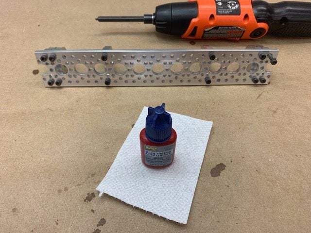
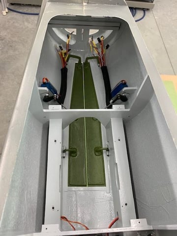
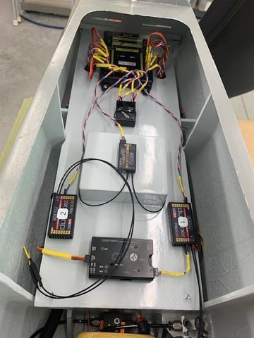
Radio tray assembled with all components attached. Fuel tray assembled with safety wire on tubing.
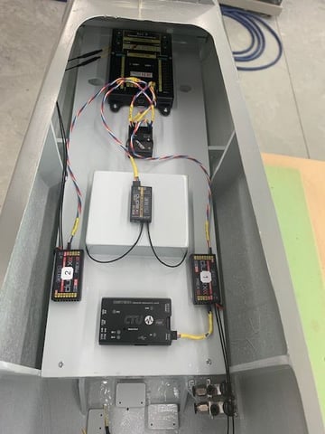
Radio tray test fit
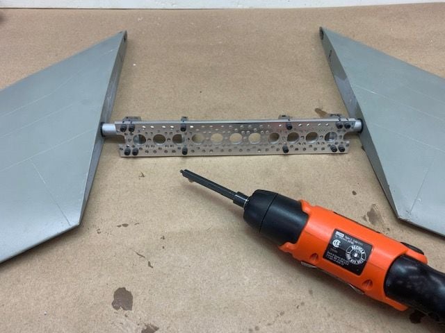
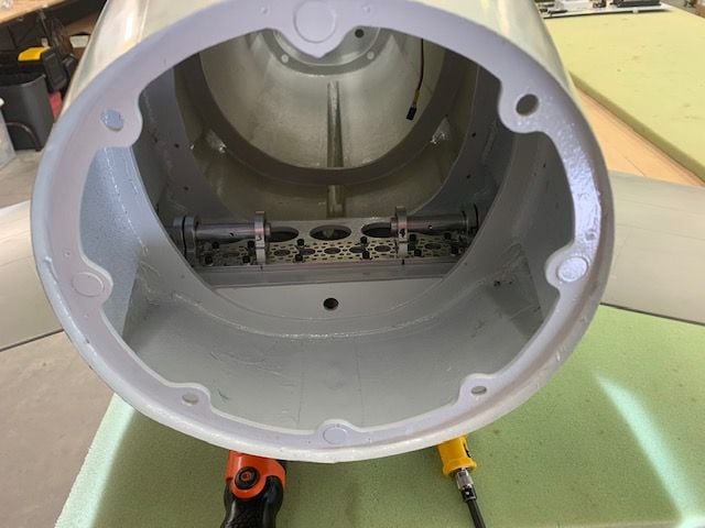
Turbine mounts assembled and installed
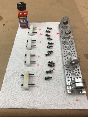
VC-3 Vibra Tite thread locker painted on assembly bolts

Nylon block wing spar guided installed
Blue thread locker on stab mount bolts
Stabs inserted into the bearings to ensure bearings did not mis-align when tightened
Stab bearing assembly installed in fuse
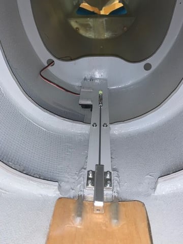
Drag chute release assembly installed
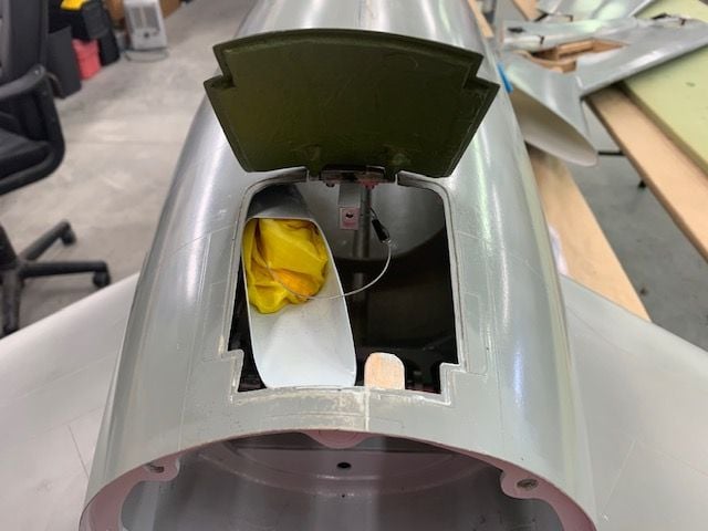
Drag chute tube and actuator installed
Drag chute tube from top. Inside of the chute door will be painted zinc chromate green when I get the paint
Air valves and air input manifold installed.
This is kind of like an ARFassembly with the pre made parts are being installed. More to follow!
Radio tray assembled with all components attached. Fuel tray assembled with safety wire on tubing.
Radio tray test fit
Turbine mounts assembled and installed
VC-3 Vibra Tite thread locker painted on assembly bolts
Nylon block wing spar guided installed
Blue thread locker on stab mount bolts
Stabs inserted into the bearings to ensure bearings did not mis-align when tightened
Stab bearing assembly installed in fuse
Drag chute release assembly installed
Drag chute tube and actuator installed
Drag chute tube from top. Inside of the chute door will be painted zinc chromate green when I get the paint
Air valves and air input manifold installed.
This is kind of like an ARFassembly with the pre made parts are being installed. More to follow!
01-21-2021, 05:28 PM
#832
Thread Starter
My Feedback: (20)
More fuse re-assembly
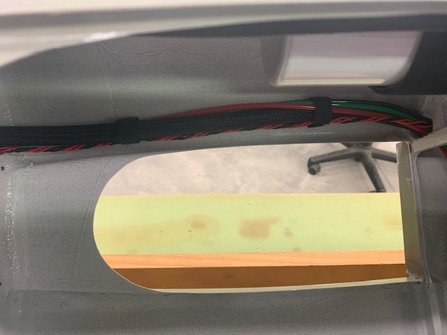
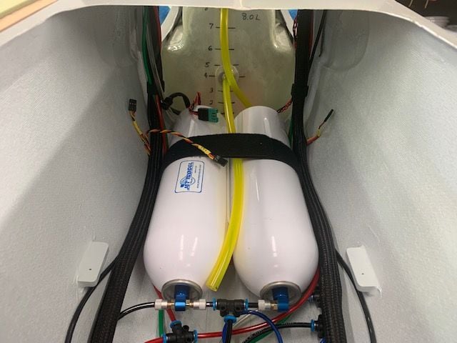
I robbed some 1/16" inch thick craft foam from my wife's craft room to make a thin pad between the air tanks and the fuse bottom. It gives some extra friction to prevent shifting between the side stops. The stuff weighs near nothing and gives a nice pad below air tanks. I'll use some below the fuel tank also.
Main fuel line between filter and shut off valve installed.
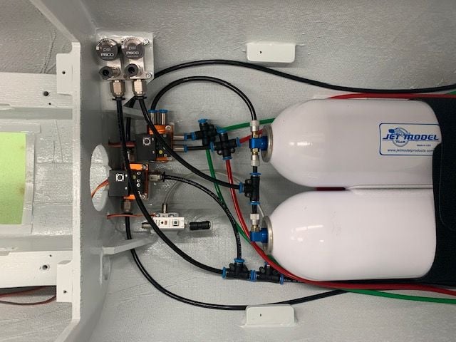
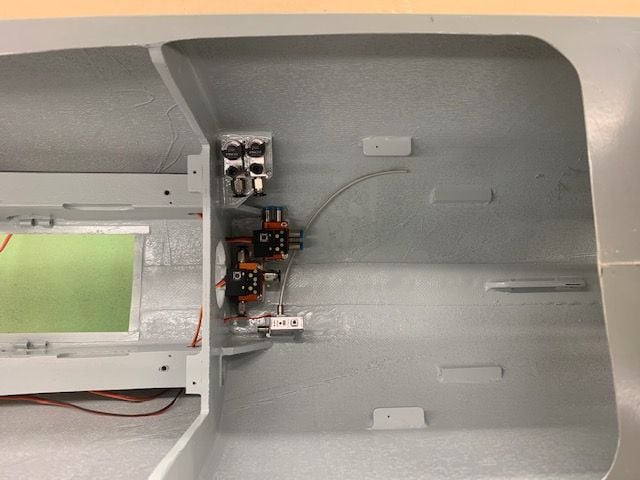
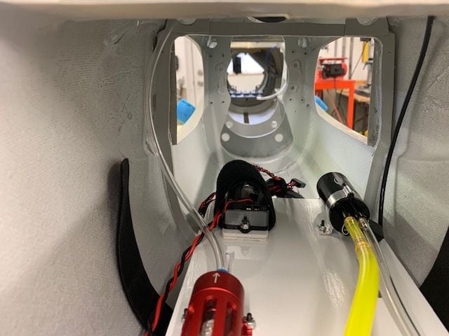
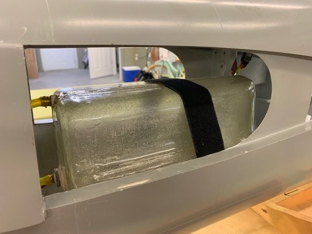
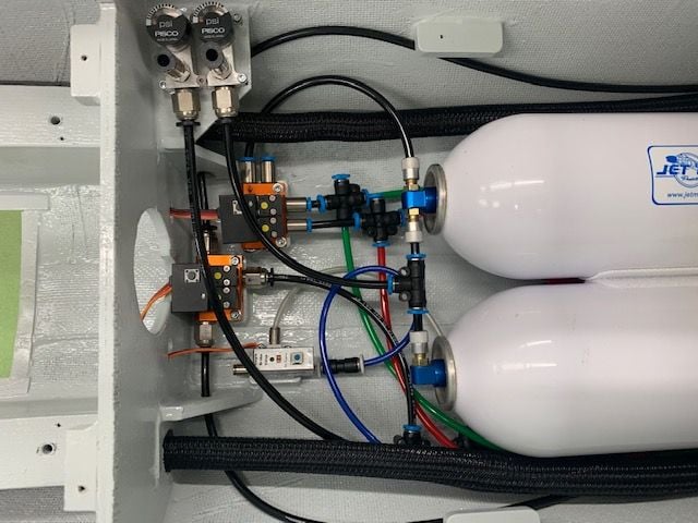
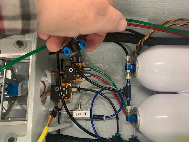
Front end of the air system installed and connected except the line to the drag chute cylinder. Lower tanks are for gear ops and upper tank (not shown) is for brakes and drag chute deploy.

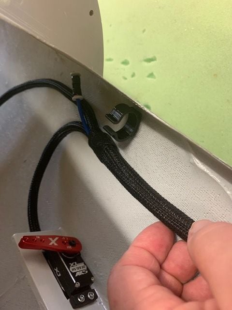
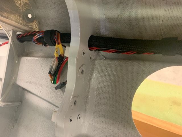
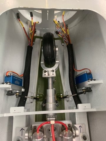
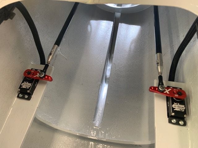
Left servo cable sleeve installed after I added an another wire for the Mrpm sensor that will be on the left main wheel to sense ground speed for drag chute deployment. I also ran the air line for the drag chute cylinder inside the sleeve and installed a push to connect coupler in the air line to allow the drag chute assembly to easily be removed for servicing if necessary. The left elevator servo is installed and connected to the servo cable in the sleeve. I changed the servo arms to heavy duty metal ones with a deep thread for the 3mm bolt holding the ball joint. Also the arm has the first hole closer that the original arm and that reduces the minimum servo torque requirement 80 in/oz from what I calculated before. Now I only need 408 in/oz according to the AMA formula. The servos provide 538 in/oz at 7.4v.
RIght elevator servo installed.
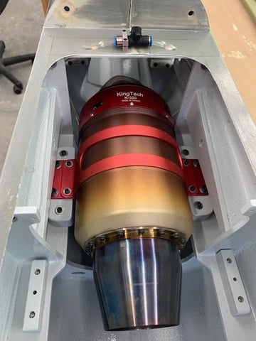
Fuel line from filter to shut off valve installed along with the turbine electrical and data cables. This is the K-320G2 I had in my Havoc last summer. Things are going well and I hope to have it all back together this weekend if I can stay in the shop...but we all know how that plan works!
I robbed some 1/16" inch thick craft foam from my wife's craft room to make a thin pad between the air tanks and the fuse bottom. It gives some extra friction to prevent shifting between the side stops. The stuff weighs near nothing and gives a nice pad below air tanks. I'll use some below the fuel tank also.
Main fuel line between filter and shut off valve installed.
Front end of the air system installed and connected except the line to the drag chute cylinder. Lower tanks are for gear ops and upper tank (not shown) is for brakes and drag chute deploy.
Left servo cable sleeve installed after I added an another wire for the Mrpm sensor that will be on the left main wheel to sense ground speed for drag chute deployment. I also ran the air line for the drag chute cylinder inside the sleeve and installed a push to connect coupler in the air line to allow the drag chute assembly to easily be removed for servicing if necessary. The left elevator servo is installed and connected to the servo cable in the sleeve. I changed the servo arms to heavy duty metal ones with a deep thread for the 3mm bolt holding the ball joint. Also the arm has the first hole closer that the original arm and that reduces the minimum servo torque requirement 80 in/oz from what I calculated before. Now I only need 408 in/oz according to the AMA formula. The servos provide 538 in/oz at 7.4v.
RIght elevator servo installed.
Fuel line from filter to shut off valve installed along with the turbine electrical and data cables. This is the K-320G2 I had in my Havoc last summer. Things are going well and I hope to have it all back together this weekend if I can stay in the shop...but we all know how that plan works!
01-21-2021, 05:32 PM
#833
Thread Starter
My Feedback: (20)
Thanks for the compliments guys.
Frank asked me a question about the Vibra Tite VC-3 thread locker I used on some of the bolts vs the standard blue thread locker. I found it several years ago at Don's Hobby Shop in KS for use on bolts that need to be removeable but still have vibration resistance. I started using it on big gasser cowls and found it worked really well and did not glue in the treads like the blue stuff. Its kind of like red rubber cement on the threads. For anything I think I might need to remove for service I use it. For stuff like set screws and the stab bearing bolts I used the blue stuff. The last bottle I got from Amazon.
Gary
Last edited by Viper1GJ; 01-21-2021 at 05:43 PM.
The following users liked this post:
jsnipes (01-21-2021)
01-22-2021, 05:17 PM
#835
Thread Starter
My Feedback: (20)
Fuse assembly continued...
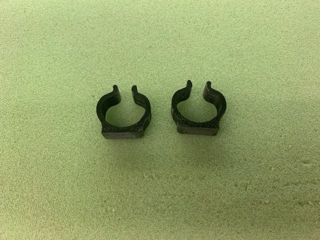
I got a 3D printer for Christmas. Been printing lots of toys for grandkids and test stuff. Finally got my first RC parts off the thing today. Needed some large cable clips so I enlarged some clips from Thingiverse and printed them in black PLA. So that makes these clips about $250 apiece! I still don't have a clue about how to design something in CAD yet but I can see a new adventure there.
Clips installed over the elevator servos
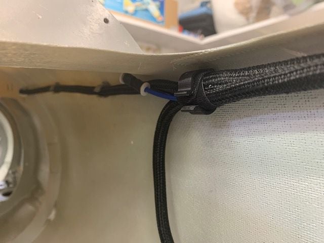
Clips worked well. The smaller ones to the rear are from Ultimate Jets. The drag chute PTC connector came in handy already as I had to remove the drag chute assembly to get the servo cables installed.
Rudder and drag chute release servo cables installed.
WIng servo connectors secured with thin Velcro one wrap.
Cable bundle secured with Velcro wraps again
1/16" craft foam on tank floor
Fuel tank installed and secured with 1.5" Velcro one wrap
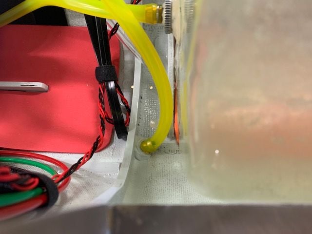
Fuel tank vent tube attached to vent overflow nipple
Blue drag chute deploy air line attached to Jet Tronics valve. Had to make a loop to avoid sharp bend in tubing
Zinc chromate green paint arrived just in time to paint the inside of the nose gear doors before installing them. If I ever get around to painting the outside of the jet I will not take them off for painting since they are a real pain to get on and off.
I also got the inside of the drag chute door since I was swinging the water color brush around.
Well so much for staying in the shop this weekend. Command post has scheduled a shopping trip to the big city tomorrow. At least the paint will be dry when I get back.
I got a 3D printer for Christmas. Been printing lots of toys for grandkids and test stuff. Finally got my first RC parts off the thing today. Needed some large cable clips so I enlarged some clips from Thingiverse and printed them in black PLA. So that makes these clips about $250 apiece! I still don't have a clue about how to design something in CAD yet but I can see a new adventure there.
Clips installed over the elevator servos
Clips worked well. The smaller ones to the rear are from Ultimate Jets. The drag chute PTC connector came in handy already as I had to remove the drag chute assembly to get the servo cables installed.
Rudder and drag chute release servo cables installed.
WIng servo connectors secured with thin Velcro one wrap.
Cable bundle secured with Velcro wraps again
1/16" craft foam on tank floor
Fuel tank installed and secured with 1.5" Velcro one wrap
Fuel tank vent tube attached to vent overflow nipple
Blue drag chute deploy air line attached to Jet Tronics valve. Had to make a loop to avoid sharp bend in tubing
Zinc chromate green paint arrived just in time to paint the inside of the nose gear doors before installing them. If I ever get around to painting the outside of the jet I will not take them off for painting since they are a real pain to get on and off.
I also got the inside of the drag chute door since I was swinging the water color brush around.
Well so much for staying in the shop this weekend. Command post has scheduled a shopping trip to the big city tomorrow. At least the paint will be dry when I get back.
01-23-2021, 05:23 PM
#836
Thread Starter
My Feedback: (20)
I got a couple of hours shop time today. Install continues...
The main objective now is to get everything installed and connected to see if it all works. The untested system is the landing gear pneumatic system. I need to find out if it will work on internal air pressure and valves. That's the next big question.
Nose gear doors installed with 2mm bolts in hinges
Nose gear installed
Nose gear servos powered up through the radio and the servo arms attached on the correct angle for proper door travel and bolted on to servos. I was smart enough to drill a hole in the former to insert a ball driver through it and tighten the servo arm bolts down.
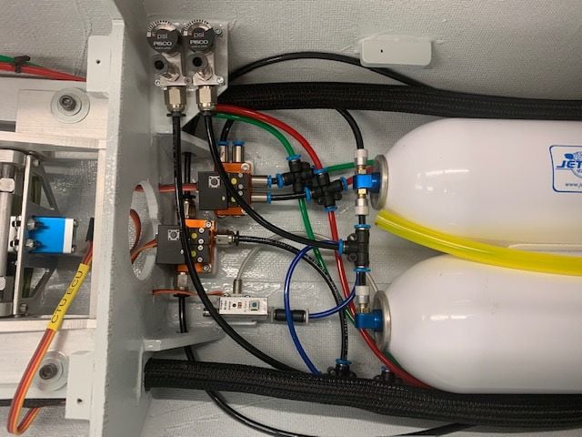
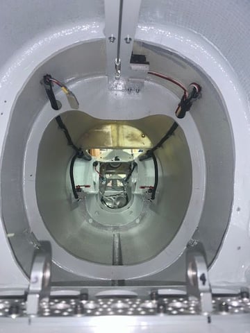
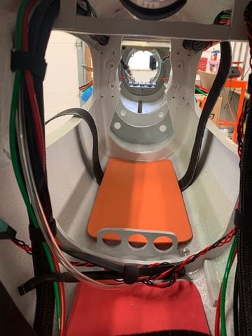
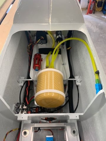
The pneumatic plumbing "farm" is complete
Throttle, GSU, and CTU wires from ECU run inside the servo cables from the rear of the fuel tray area. I had to take out the braided sleeves 3 times to get it all figured out and installed. Fuel tray is ready to install now.
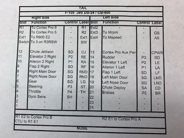
The latest version of my CB400 map. Tail is the top and nose is the bottom. Will be very useful now.
The main objective now is to get everything installed and connected to see if it all works. The untested system is the landing gear pneumatic system. I need to find out if it will work on internal air pressure and valves. That's the next big question.
Nose gear doors installed with 2mm bolts in hinges
Nose gear installed
Nose gear servos powered up through the radio and the servo arms attached on the correct angle for proper door travel and bolted on to servos. I was smart enough to drill a hole in the former to insert a ball driver through it and tighten the servo arm bolts down.
The pneumatic plumbing "farm" is complete
Throttle, GSU, and CTU wires from ECU run inside the servo cables from the rear of the fuel tray area. I had to take out the braided sleeves 3 times to get it all figured out and installed. Fuel tray is ready to install now.
The latest version of my CB400 map. Tail is the top and nose is the bottom. Will be very useful now.
 01-25-2021, 04:26 PM
#838
Thread Starter
My Feedback: (20)
Hook up of fuel and radio trays
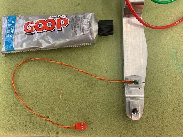
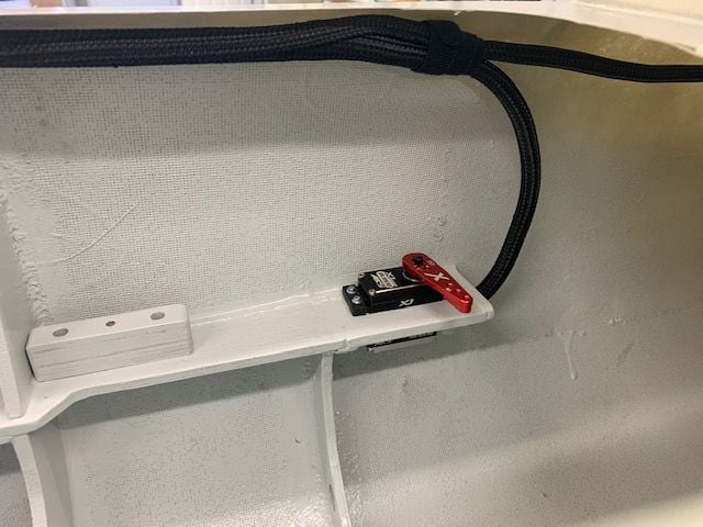
Jeti MRPM sensor mounted to gear strut in the 3D printed plastic mount with Goop. This was followed by 2 days of testing and frustration trying to get it to work in the CB400 port. It would work when attached to the receivers but not the CB 400. Apparently a year and half ago when testing with just one receiver it logged the sensor ID in the receiver and the CB400 would not see it. After a call to James at Esprit he had me relog all the attached sensors and there it was. One button push and done! Works now as planned. Thank goodness for smart guys who will steer me straight!
Fuel tray installed and all hookups completed for the first time except for the safety wires on the air trap tank. Fuel fill tubing was added. The ECU cables were easier than I thought it would be but I ran into a show stopper. The hole in the former is not large enough to push the ECU battery plug through with the servo cable in the hole, so I have to either splice the wire and plan to leave it in there or remove the servo cable loom and make the hole larger. Either option will wait till I can get a rough CG estimate and determine where the batteries will go. I'm expecting to have them as far forward as possible. TBD.
The RC tray was installed for the first time and all the hook ups made in the CB400. This was difficult. I've never had an airplane, no matter how big, that there was not something that was hard to do because of a tight space. This was it. Very difficult to stuff all the wires through the tray working through the nose gear doors. In addition somehow the cables and loom got shorter than the mock up and there is not enough slack in some of the servo wires. I will have to relocate the servo cable looms and some wires inside. This will wait until after initial testing of all the systems is done.
The location of the R900 receiver is still TBD. It could be on the tray next to the RC switch receiver in the middle or on the fuse side. TBD based on location of the other receiver antennas. There is a 5" band of carbon fiber under the rear former in the photo molded into the fuse sides that I have to avoid with all antennas.
Also I will have to wait till I get the new landing gear blocks back from Larry to test the landing gear retract operation. Without the blocks installed the main gear will not rotate when retracting and fit into the gear wells. Still lots to do on other stuff. I plan to test and adjust all the flight controls and gear doors next. I can also test and adjust brakes and drag chute and release with out swinging the gear.
This was one of those days that I was wondering if anybody wants an almost done F-105...Going to work on a foamy jet tomorrow!
Last edited by Viper1GJ; 01-25-2021 at 04:30 PM.
01-29-2021, 06:00 PM
#839
Thread Starter
My Feedback: (20)
Two days off the F-105 to get the foamy F-4 ready to fly were good and allowed me a little attitude readjustment.
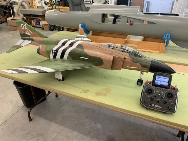
Freewing F-4 is now RTF again with a new Xicoy X-45 and updated brakes. Will fly when it gets warmer outside.
F-105 final assembly for systems testing
Elevator servos installed with new heavy duty servo arms with shorter arm holes. Pushrods attached with 3mm bolts
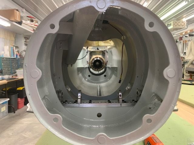
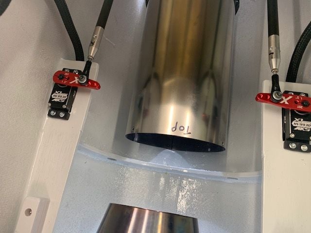
Drag chute tube installed. Vertical fin clamped to fuse former for testing and rudder servo connected. Here is where I found for sure that the pipe could not be inserted with the bell mouth on. I suspected it would be a problem but I never had everything connected and tried to put it in.
 \
\
Getting the pipe in required taking off the bell mouth. Here is where a small mouth pipe would work best, similar to what Tam used to make. However, I am going with what I got since it would require a whole new pipe and rebuilding the pipe mounts. Not now!
After some fussing with the bell I sanded a bevel on the trailing edge of the bell and got it to slide inside the pipe pretty easy. Now I just have to reinstall the 4 x 4-40 stainless bolts and nuts.
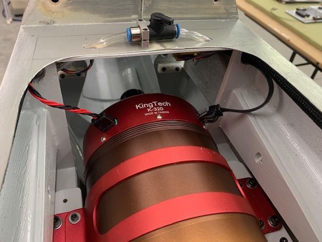
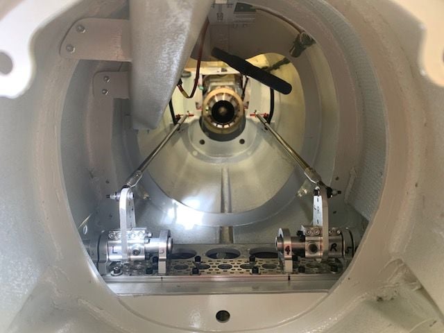
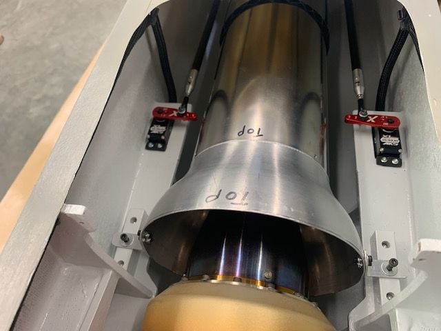
Turbine is centered.
Pushrods had plenty of clearance from pipe.
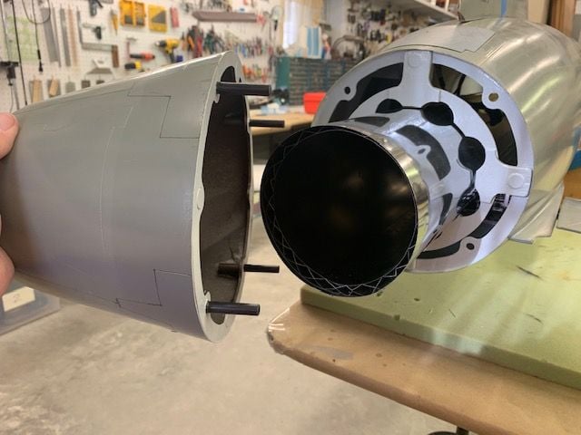
Rear pipe retainer ring and afterburner nozzle installed with the magnets. The are very strong and take quite a force to pull off.
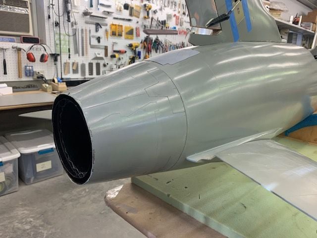
Tailpipe done
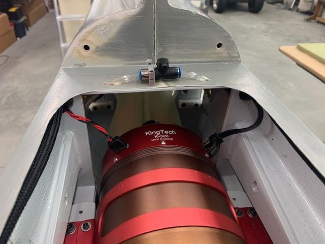
Turbine connections made. It was actually pretty easy to connect the fuel line on the bottom by sticking my hand over the top of the turbine
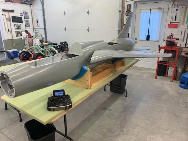
Ready for first all connected systems tests.
To my surprise everything worked. After some adjustments the stabs were much better. The heavy duty servo arms and shorter arm length made an improvement. The rudder, ailerons, and flaps were already programmed and worked as planned. The main gear doors worked. The turbine worked correctly after I remembered to do the learn RC procedure. I will connect the nose gear doors and steering tomorrow and then program the Cortex Pro gyro.
I will test the air systems as much as possible with out the main gear installed. Larry is sending back the epoxy potted gear blocks modified for testing and will send the final parts later. Still lots to do like testing the MRPM sensor, building the pitot static system, cockpit, and canopy, but it is starting to work like an airplane now.
One of my big concerns now after putting everything together is total weight. It feels really heavy and my main concern is if the gear and gear mounts will be up to the task. We will see.
Freewing F-4 is now RTF again with a new Xicoy X-45 and updated brakes. Will fly when it gets warmer outside.
F-105 final assembly for systems testing
Elevator servos installed with new heavy duty servo arms with shorter arm holes. Pushrods attached with 3mm bolts
Drag chute tube installed. Vertical fin clamped to fuse former for testing and rudder servo connected. Here is where I found for sure that the pipe could not be inserted with the bell mouth on. I suspected it would be a problem but I never had everything connected and tried to put it in.
\Getting the pipe in required taking off the bell mouth. Here is where a small mouth pipe would work best, similar to what Tam used to make. However, I am going with what I got since it would require a whole new pipe and rebuilding the pipe mounts. Not now!
After some fussing with the bell I sanded a bevel on the trailing edge of the bell and got it to slide inside the pipe pretty easy. Now I just have to reinstall the 4 x 4-40 stainless bolts and nuts.
Turbine is centered.
Pushrods had plenty of clearance from pipe.
Rear pipe retainer ring and afterburner nozzle installed with the magnets. The are very strong and take quite a force to pull off.
Tailpipe done
Turbine connections made. It was actually pretty easy to connect the fuel line on the bottom by sticking my hand over the top of the turbine
Ready for first all connected systems tests.
To my surprise everything worked. After some adjustments the stabs were much better. The heavy duty servo arms and shorter arm length made an improvement. The rudder, ailerons, and flaps were already programmed and worked as planned. The main gear doors worked. The turbine worked correctly after I remembered to do the learn RC procedure. I will connect the nose gear doors and steering tomorrow and then program the Cortex Pro gyro.
I will test the air systems as much as possible with out the main gear installed. Larry is sending back the epoxy potted gear blocks modified for testing and will send the final parts later. Still lots to do like testing the MRPM sensor, building the pitot static system, cockpit, and canopy, but it is starting to work like an airplane now.
One of my big concerns now after putting everything together is total weight. It feels really heavy and my main concern is if the gear and gear mounts will be up to the task. We will see.
Last edited by Viper1GJ; 01-29-2021 at 06:12 PM.
The following users liked this post:
RickP (01-30-2021)
01-30-2021, 05:42 PM
#843
Thread Starter
My Feedback: (20)
Nose gear, nose doors, main gear doors, and pitot tube
Not much shop time today so I continued working on radio programming and systems tests. I got all the flight controls programmed, mixed, travel adjusted dual rates, etc. I got the Cortex Pro programmed and checked for proper flight control movements with rates set for flaps up, flaps half, and full flaps. No air systems tested yet.
Next I manually dropped the nose gear and plugged in the nose gear steering to adjust the travel limits and centering.
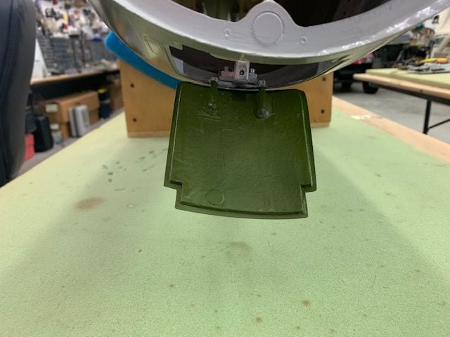
Next I adjusted the nose door travel to max opening to clear the nose gear during retraction.
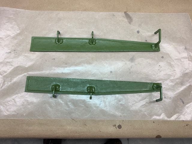
The nose gear was manually retracted and then the nose gear doors were adjusted for closed position. There were no doors included with the kit parts so I made these nose doors from the recessed cut outs in the fuse mold. I am real happy with how they turned out.
Next the main gear doors were adjusted for open...

Then closed. Next tests will be the air systems and gear.
I connected the Mspeed sensor to the Jeti pitot tube and got the airspeed system working. I am running an airspeed call out Lua program by Dave called "Speed Announcer" It will call out the current airspeed in MPH when selected and can be set for continuous at the desired interval or to an interval based on speed changes. It even has an "airspeed alive", Vref, and Stall calls. Its all selectable, fun, and very useful IMO.

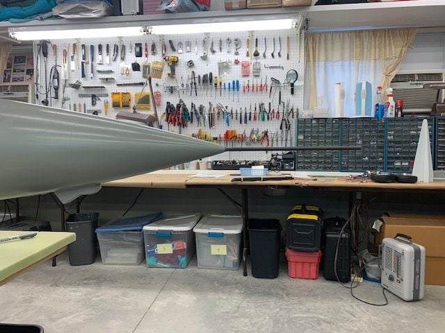
Now we need an F-105 pitot tube. Here is a pic of a real one. Now I need to make a scale on, well sort off... I want one that will push back into the radome when not in use to keep me from smashing in to it when walking around the jet and breaking it off. Ask me how I know...
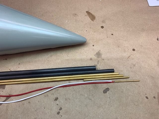
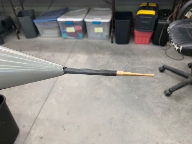
I found a bunch of telescoping tube sizes in the tubing junk box. The bottom is the Jeti brass pitot tube connected to the dynamic (red) and static (white) output tubes going to the sensor.
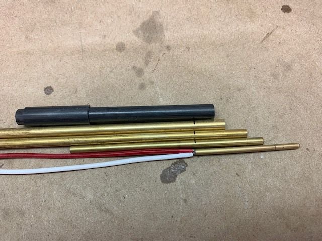
The design idea is to have the pitot tube push back into the larger carbon sleeve inside the nose. The cut lines on the brass parts are shown here
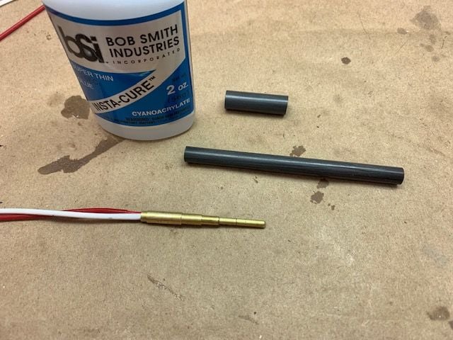
I glued the brass tubes together with thin CA. I will put Icing body filler around the tubes and sand to a smooth taper to try and make it look like the real one except at the tip where he static and dynamic holes are. Some silver paint and it will be stand way off scale.
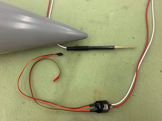
Then the brass tubes were glued into the thinner carbon tube which will slide into the larger carbon sleeve inside the nose. To be continued...
Not much shop time today so I continued working on radio programming and systems tests. I got all the flight controls programmed, mixed, travel adjusted dual rates, etc. I got the Cortex Pro programmed and checked for proper flight control movements with rates set for flaps up, flaps half, and full flaps. No air systems tested yet.
Next I manually dropped the nose gear and plugged in the nose gear steering to adjust the travel limits and centering.
Next I adjusted the nose door travel to max opening to clear the nose gear during retraction.
The nose gear was manually retracted and then the nose gear doors were adjusted for closed position. There were no doors included with the kit parts so I made these nose doors from the recessed cut outs in the fuse mold. I am real happy with how they turned out.
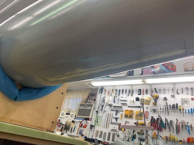
Next the main gear doors were adjusted for open...
Then closed. Next tests will be the air systems and gear.
I connected the Mspeed sensor to the Jeti pitot tube and got the airspeed system working. I am running an airspeed call out Lua program by Dave called "Speed Announcer" It will call out the current airspeed in MPH when selected and can be set for continuous at the desired interval or to an interval based on speed changes. It even has an "airspeed alive", Vref, and Stall calls. Its all selectable, fun, and very useful IMO.
Now we need an F-105 pitot tube. Here is a pic of a real one. Now I need to make a scale on, well sort off... I want one that will push back into the radome when not in use to keep me from smashing in to it when walking around the jet and breaking it off. Ask me how I know...
I found a bunch of telescoping tube sizes in the tubing junk box. The bottom is the Jeti brass pitot tube connected to the dynamic (red) and static (white) output tubes going to the sensor.
The design idea is to have the pitot tube push back into the larger carbon sleeve inside the nose. The cut lines on the brass parts are shown here
I glued the brass tubes together with thin CA. I will put Icing body filler around the tubes and sand to a smooth taper to try and make it look like the real one except at the tip where he static and dynamic holes are. Some silver paint and it will be stand way off scale.
Then the brass tubes were glued into the thinner carbon tube which will slide into the larger carbon sleeve inside the nose. To be continued...
Last edited by Viper1GJ; 01-30-2021 at 05:51 PM.
01-31-2021, 02:56 PM
#844
Thread Starter
My Feedback: (20)
Pitot tube install
Started with a very small drill hole and worked up the size to here after several passes to avoid cracking the nose cone
Inserted a perma grit round file in the drill to enlarge the hole and keep it on center
Finished up with a perma grit hand held round file to get the final 10mm hole
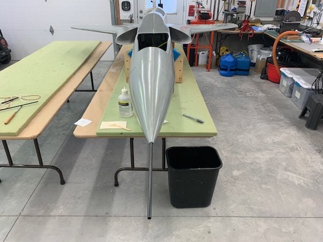
10mm carbon sleeve inserted
Carbon sleeve tack glued into the nose cone with 5 min epoxy. I inserted a longer carbon tube in the sleeve to eyeball the alignment during the cure time.
No way to measure it just TLAR from side and front
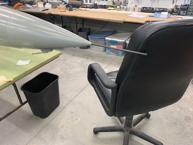
Tube kept pulling to the left so I propped my chair against it to hold till cured.
Longer tube used to check alignment after epoxy cure. Looked OK from front and top
Side view looked ok here
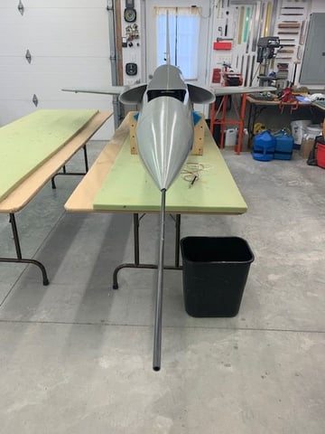
Pitot tube checked in place
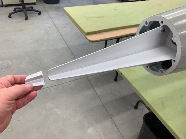
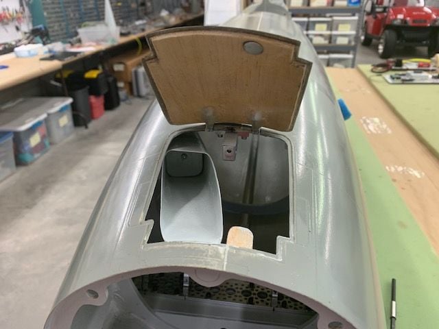
Nose tray had to be shortened about 1.5" to allow pitot tube to be pushed back inside the nose cone

Icing body filler applied and sanded to shape
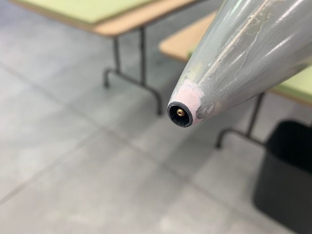
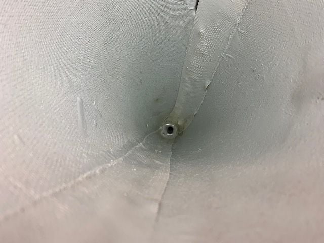
Pitot tube recessed inside nose cone where I can't walk into it and bust it off!
10 grams of laminating epoxy poured around the base of the carbon sleeve to secure it in the nose cone
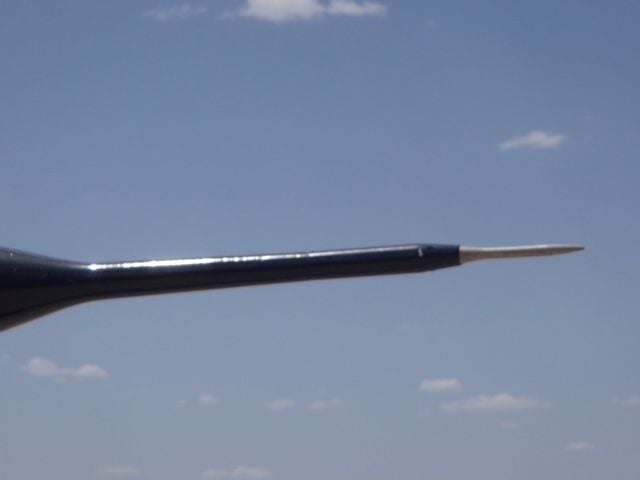
Here's the full scale tube
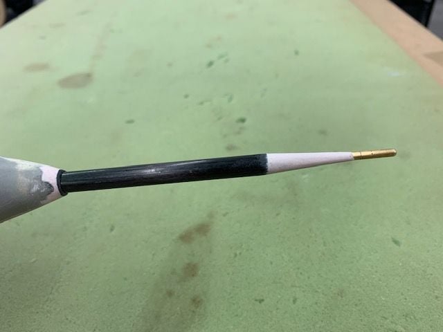
Here's mine. Good enough!
Started with a very small drill hole and worked up the size to here after several passes to avoid cracking the nose cone
Inserted a perma grit round file in the drill to enlarge the hole and keep it on center
Finished up with a perma grit hand held round file to get the final 10mm hole
10mm carbon sleeve inserted
Carbon sleeve tack glued into the nose cone with 5 min epoxy. I inserted a longer carbon tube in the sleeve to eyeball the alignment during the cure time.
No way to measure it just TLAR from side and front
Tube kept pulling to the left so I propped my chair against it to hold till cured.
Longer tube used to check alignment after epoxy cure. Looked OK from front and top
Side view looked ok here
Pitot tube checked in place
Nose tray had to be shortened about 1.5" to allow pitot tube to be pushed back inside the nose cone
Icing body filler applied and sanded to shape
Pitot tube recessed inside nose cone where I can't walk into it and bust it off!
10 grams of laminating epoxy poured around the base of the carbon sleeve to secure it in the nose cone
Here's the full scale tube
Here's mine. Good enough!
The following users liked this post:
jsnipes (02-01-2021)
 02-01-2021, 03:45 PM
#847
Thread Starter
My Feedback: (20)
Auburn, the friction fit between the two carbon tubes is really good on this one. On previous installs like this I've used some thin tape or a drop of thin CA sanded to get a good fit.
02-01-2021, 05:09 PM
#848
Thread Starter
My Feedback: (20)
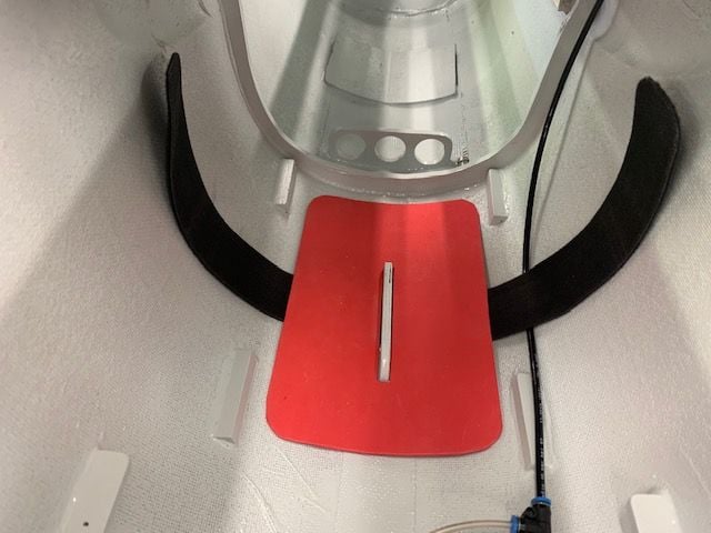
Drag chute testing
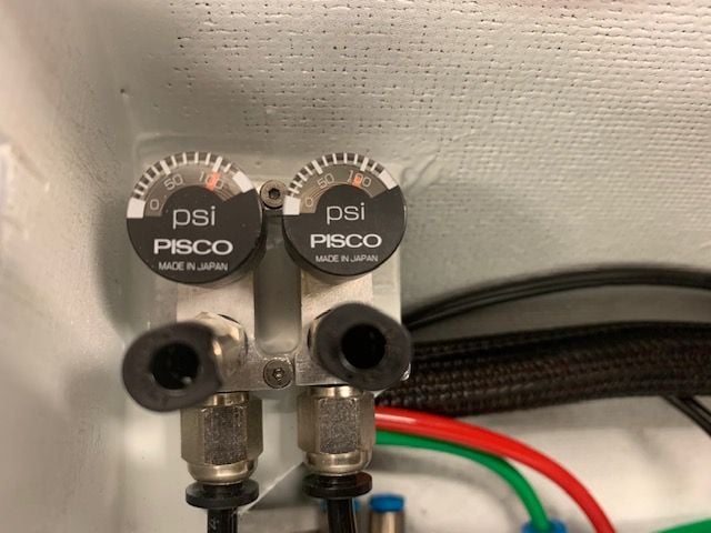
I put air in the tanks for the first time. I immediately heard air hissing and started looking. I took out the fuel tray so I could see all the tubing connections and finally traced the leak to the push to connect fill port on the right side. (Brakes/drag chute on left and gear on the right.) It turned out that the fill port was not tightened down to the manifold block and was leaking. I tightened both ports and had 100 psi all day with no observable leaks. I'll check it again tomorrow after it sits overnight. So far the air system looks good.
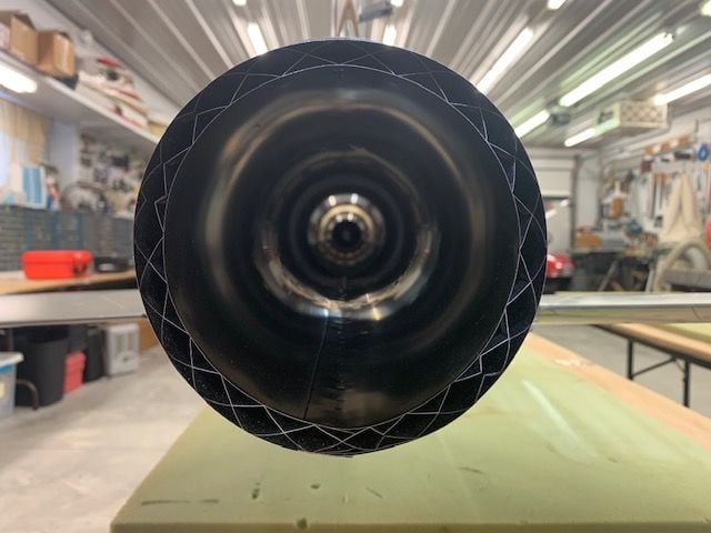
After several attempts at folding the chute different ways and winding the lanyards and steel leader line I figured out how best to load it. Dave's drag chute Lua program for the Jeti has a "Load" and "Test" mode built in for bench testing and it is real convenient. There is no need to have the gear, throttle, flaps, and wheel spin up for bench testing the deploy and jettison functions.
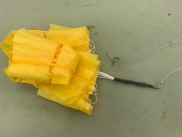
After a few tangled attempts I called my friend Frank who has been using a drag chute for years in his J-35 Draken. He suggested taping or heat shrinking the lanyard knot and loose ends plus the swivel to make the joints smooth and reduce snags. I applied heat shrink over the knot and swivel and it worked.
Drag chute test video:
After being happy with the drag chute test I decided to test the nose gear. I hooked up the nose gear air lines and cycled the valve. Long story short it would not extend without me pushing the over center bar out of the lock. It retracted very fast and hit the bottom of the RC tray under the CB400. I didn't see that coming. The saga continues...
I put air in the tanks for the first time. I immediately heard air hissing and started looking. I took out the fuel tray so I could see all the tubing connections and finally traced the leak to the push to connect fill port on the right side. (Brakes/drag chute on left and gear on the right.) It turned out that the fill port was not tightened down to the manifold block and was leaking. I tightened both ports and had 100 psi all day with no observable leaks. I'll check it again tomorrow after it sits overnight. So far the air system looks good.
After several attempts at folding the chute different ways and winding the lanyards and steel leader line I figured out how best to load it. Dave's drag chute Lua program for the Jeti has a "Load" and "Test" mode built in for bench testing and it is real convenient. There is no need to have the gear, throttle, flaps, and wheel spin up for bench testing the deploy and jettison functions.
After a few tangled attempts I called my friend Frank who has been using a drag chute for years in his J-35 Draken. He suggested taping or heat shrinking the lanyard knot and loose ends plus the swivel to make the joints smooth and reduce snags. I applied heat shrink over the knot and swivel and it worked.
Drag chute test video:
After being happy with the drag chute test I decided to test the nose gear. I hooked up the nose gear air lines and cycled the valve. Long story short it would not extend without me pushing the over center bar out of the lock. It retracted very fast and hit the bottom of the RC tray under the CB400. I didn't see that coming. The saga continues...
02-02-2021, 05:17 PM
#849
Thread Starter
My Feedback: (20)
Landing gear test fails...
Not a good day in the shop today. The only good thing I got done was to figure out that nothing worked! It started on a positive, I saw that both air systems did not loose pressure overnight. Not bad.
Next I took out the RC tray to investigate the nose gear extend failure. I hooked up the gear valve with an extension an laid the tray on the table. Batteries connected, switch on, and nothing. Not any receiver would come on. CB400 on, CTU on, Cortex Pro blinking red. but not one receiver. What's up, I used the radio all day yesterday. The only change was taking it out of the jet. Finally after about 30 min I realized that I had unplugged from the CB400 the 900mhz back up receiver to take it out of the jet. I plugged the R900 back in and it all worked. So if you remove the 900mhz back up receiver the whole system will not turn on. Go figure!
Now I was ready to test the nose gear. Air in tanks, switch on, gear switch down. Click, nothing. Then I saw that the two cylinders were not pulling the unlock bar in the slots at the same time. The right cylinder was pulling the over center lock out but the left cylinder was not. I tried pushing it with my finger and the gear immediately extended...with my finger still the mechanics. My first thought was that was dumb, and it was... and then it bled. I got back to the shop an hour and half later with a bandage on the finger and throbbing finger nail. Could have done it easier with a hammer.
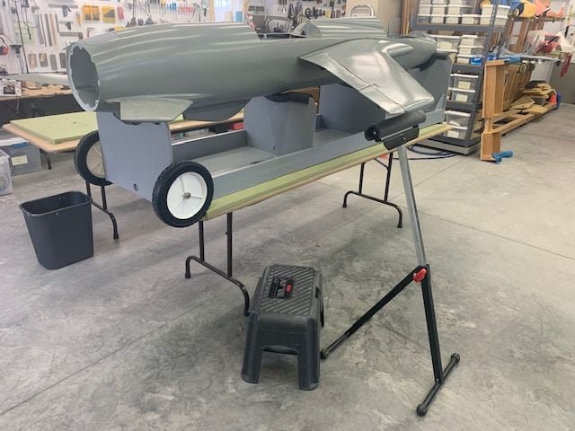
During my break I decided to work on the main gear and leave the nose gear for later. That required getting the jet on the dolly and putting the wings on. This took a while as the wing assembly is not easy or fast. Being short, this required a step stool and a saw stand to hold the wing tip while plugging in the wires and air lines. Finally got it done with wounded finger.
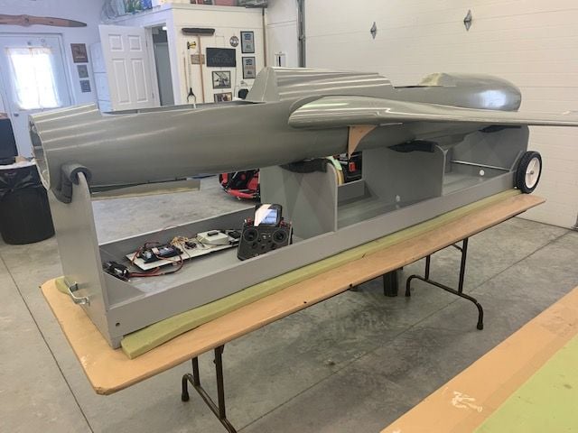
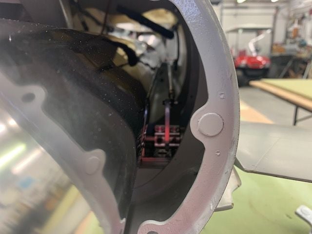
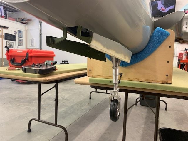
This is the test setup. RC tray in dolly connected by extension to gear valve. Main and nose doors open but not plugged in. Ready to go.
Shop air filled the tanks, switch on, gear down. The mains came down hard. The nose stuck up. With the help of a SCREWDRIVER, I pushed the lock bar and the nose gear extended hard. I will have to look at some inline valves to act as restrictors. Gear switch up, the mains barely made it into the wheel wells. The nose slammed up.
After more experimenting and calls to three of my buddies, Tom, Jamie, and Larry, I decided to isolate the mains and connect them one at a time to the valve. This pic shows the right main connected directly to the valve. And it worked better. The retraction is much better with more power and the wheel goes up and locks each time. Still slams down. Left main checked out the same. It seems like there may be a flow issue though the valve when all three gears are connected to the same valve. I don't how all the gear run thru separate valves would work because they are still all fed by a single 4mm line from the tanks. Open to suggestions and solutions from available hardware!
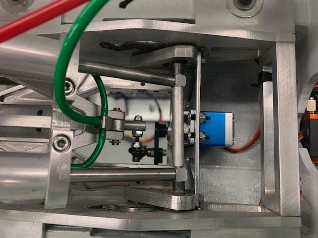
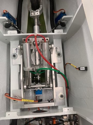
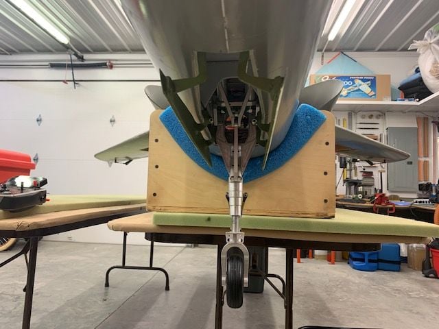
Back to the nose gear. Pic shows nose gear assembly from top, nose is to left. When valve is commanded to extend air pressure goes into the green lines and pushed pistons to the left. The right (top) cylinder pulls the bar out of the lock slot but the left cylinder (bottom) is jammed. A slight tug upwards on the wheel will release the bind and the gear functions...fast.

I tried dry lube on the slots and no luck. Both cylinders have already been treated with BVM lube oil. I can see no reason that the pressures are not he same in both cylinders, so my theory is a mechanical bind in the mechanics. Still have to figure it out some way.
Here is a video of the nose gear malfunction. Extend fails 100% of the time, retract works 100% of the time.
I was expecting that the gear was the weak link on this jet from the start. I just did not know in how many ways. Suggestions welcome.
Gary
Not a good day in the shop today. The only good thing I got done was to figure out that nothing worked! It started on a positive, I saw that both air systems did not loose pressure overnight. Not bad.
Next I took out the RC tray to investigate the nose gear extend failure. I hooked up the gear valve with an extension an laid the tray on the table. Batteries connected, switch on, and nothing. Not any receiver would come on. CB400 on, CTU on, Cortex Pro blinking red. but not one receiver. What's up, I used the radio all day yesterday. The only change was taking it out of the jet. Finally after about 30 min I realized that I had unplugged from the CB400 the 900mhz back up receiver to take it out of the jet. I plugged the R900 back in and it all worked. So if you remove the 900mhz back up receiver the whole system will not turn on. Go figure!
Now I was ready to test the nose gear. Air in tanks, switch on, gear switch down. Click, nothing. Then I saw that the two cylinders were not pulling the unlock bar in the slots at the same time. The right cylinder was pulling the over center lock out but the left cylinder was not. I tried pushing it with my finger and the gear immediately extended...with my finger still the mechanics. My first thought was that was dumb, and it was... and then it bled. I got back to the shop an hour and half later with a bandage on the finger and throbbing finger nail. Could have done it easier with a hammer.
During my break I decided to work on the main gear and leave the nose gear for later. That required getting the jet on the dolly and putting the wings on. This took a while as the wing assembly is not easy or fast. Being short, this required a step stool and a saw stand to hold the wing tip while plugging in the wires and air lines. Finally got it done with wounded finger.
This is the test setup. RC tray in dolly connected by extension to gear valve. Main and nose doors open but not plugged in. Ready to go.
Shop air filled the tanks, switch on, gear down. The mains came down hard. The nose stuck up. With the help of a SCREWDRIVER, I pushed the lock bar and the nose gear extended hard. I will have to look at some inline valves to act as restrictors. Gear switch up, the mains barely made it into the wheel wells. The nose slammed up.
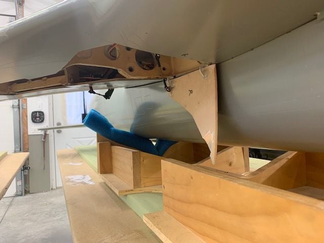
After more experimenting and calls to three of my buddies, Tom, Jamie, and Larry, I decided to isolate the mains and connect them one at a time to the valve. This pic shows the right main connected directly to the valve. And it worked better. The retraction is much better with more power and the wheel goes up and locks each time. Still slams down. Left main checked out the same. It seems like there may be a flow issue though the valve when all three gears are connected to the same valve. I don't how all the gear run thru separate valves would work because they are still all fed by a single 4mm line from the tanks. Open to suggestions and solutions from available hardware!
Back to the nose gear. Pic shows nose gear assembly from top, nose is to left. When valve is commanded to extend air pressure goes into the green lines and pushed pistons to the left. The right (top) cylinder pulls the bar out of the lock slot but the left cylinder (bottom) is jammed. A slight tug upwards on the wheel will release the bind and the gear functions...fast.
I tried dry lube on the slots and no luck. Both cylinders have already been treated with BVM lube oil. I can see no reason that the pressures are not he same in both cylinders, so my theory is a mechanical bind in the mechanics. Still have to figure it out some way.
Here is a video of the nose gear malfunction. Extend fails 100% of the time, retract works 100% of the time.
I was expecting that the gear was the weak link on this jet from the start. I just did not know in how many ways. Suggestions welcome.
Gary
Last edited by Viper1GJ; 02-02-2021 at 05:30 PM.
02-02-2021, 06:47 PM
#850

Gary, good progress, sorry about the finger. Just think you’ll know this system inside out when done.
couple quick questions on that last video. Is that green line into the tee have a kink in it?
also, are those two cylinders identical? Ie. Same stroke length and parallel all the way when extended? If you swap them does it behave the same way or does the other side pull in first now? Just some thoughts.