


1/6 F-105 Build Thread
 12-20-2020, 02:16 PM
#801

Thread Starter
My Feedback: (20)
F-105 Mobile Cradle
While the jet was on sitting on it's wheels on my table I discovered I could not insert the outer wing bolts through the spar as long as there was weight pushing the wing up and slightly off setting the holes through the spar. So I needed a cradle to hold the gear off the ground to get the wings on with the gear down and get the wing bolts in. I had planned on modifying my old Havoc cradle for the F-105 so now was the time to do it.

The Havoc cradle made it easier for the old fart here to move it around by my self so I planned on using it for the F-105.

The 105 fuse fit best with the nose in the Havoc tail slot on the cradle so I put it in to do some measurements. The Havoc cradle was designed so that each vertical was under a fuse former so it would not deform the fiberglass on the bottom. I thought I would have to move all the vertical pieces to align with internal formers so there would be support inside. Well to my absolute amazement there was a former exactly over each vertical support in the cradle. They were not just close but were exactly over each vertical support. I did not have to move anything. I still can't believe it worked out that way. All I had to do was to cut the supports to shape and get the fuse level and resting on each one. I'd rather be lucky than good any day!

I used a pattern maker to get the bottom shape

Shapes were transferred to a file folder pattern and then transferred to the cradle and cut out.

Same process for the nose former

A jig saw was used to make the rough cuts and a drum sander used to fine tune the fit for all for verticals.

The old padding was use for test fitting

Final product finished and waiting for a trip to the hardware store for some split foam pipe insulation for padding.
While the jet was on sitting on it's wheels on my table I discovered I could not insert the outer wing bolts through the spar as long as there was weight pushing the wing up and slightly off setting the holes through the spar. So I needed a cradle to hold the gear off the ground to get the wings on with the gear down and get the wing bolts in. I had planned on modifying my old Havoc cradle for the F-105 so now was the time to do it.
The Havoc cradle made it easier for the old fart here to move it around by my self so I planned on using it for the F-105.
The 105 fuse fit best with the nose in the Havoc tail slot on the cradle so I put it in to do some measurements. The Havoc cradle was designed so that each vertical was under a fuse former so it would not deform the fiberglass on the bottom. I thought I would have to move all the vertical pieces to align with internal formers so there would be support inside. Well to my absolute amazement there was a former exactly over each vertical support in the cradle. They were not just close but were exactly over each vertical support. I did not have to move anything. I still can't believe it worked out that way. All I had to do was to cut the supports to shape and get the fuse level and resting on each one. I'd rather be lucky than good any day!
I used a pattern maker to get the bottom shape
Shapes were transferred to a file folder pattern and then transferred to the cradle and cut out.
Same process for the nose former
A jig saw was used to make the rough cuts and a drum sander used to fine tune the fit for all for verticals.
The old padding was use for test fitting
Final product finished and waiting for a trip to the hardware store for some split foam pipe insulation for padding.
Last edited by Viper1GJ; 12-20-2020 at 02:23 PM.
 12-20-2020, 02:34 PM
#803
Thread Starter
My Feedback: (20)
Gear block pin angle
I had a discussion with Larry about making the final gear blocks with the holes drilled at the correct angle for the rotation pins. I did not have a good way to measure the angel while the block was recessed inside the gear frame. I figured I could take a photo of it and measure the angel on the picture.

I stood on a ladder to get a stand off photo of each gear to reduce effects of the wide angle lens on my iPhone


I then used zoom to enlarge the gear block and took a screen shot of that


I printed out the screen shot and laid lines on the paper as best as I could using the photo.

I measured the angle with a large protractor and both sided showed 42.5 degrees. I think if Larry can machine the new block with anything close to that it will solve the tow in angle and rotation angle in the wheel well. Thanks Larry for your help.
I had a discussion with Larry about making the final gear blocks with the holes drilled at the correct angle for the rotation pins. I did not have a good way to measure the angel while the block was recessed inside the gear frame. I figured I could take a photo of it and measure the angel on the picture.
I stood on a ladder to get a stand off photo of each gear to reduce effects of the wide angle lens on my iPhone
I then used zoom to enlarge the gear block and took a screen shot of that
I printed out the screen shot and laid lines on the paper as best as I could using the photo.
I measured the angle with a large protractor and both sided showed 42.5 degrees. I think if Larry can machine the new block with anything close to that it will solve the tow in angle and rotation angle in the wheel well. Thanks Larry for your help.
The following users liked this post:
bonefishfool (12-20-2020)
01-02-2021, 04:08 PM
#806
Thread Starter
My Feedback: (20)
Wings assembly test

Finally got through all the Christmas events and chores and back to the shop. I finished the cradle with the foam pads and handle. Next step was a wing assembly test with turbine installed and gear, air lines, and servo wires installed.

Air line holder was installed in both wings to route the 4mm air lines to the wing root opening

The red up lines flex when retracted because the two cylinders move inboard

Wing air lines trimmed to final length. Brake lines are not yet installed. They will be tricky with the rotating retracts

Fuse air lines trimmed to final length

Next wings were attached. This took about an hour trying to figure out how to do it by myself. I've never had to connect the servo plugs and air lines before and hold the wing at the same time. I finally got everything figured out and aligned using a stool and ladder. I needed make sure everything tucked in ok and was not pinched or binding on anything.

The wings take 14 bolts to install and its difficult to get everything aligned while holding the wings with the gear down. Plus its much heavier with the gear installed. These are the 4 internal bolts after final tightening. Its a little tighter to access them with the turbine installed. Plus if you drop anything (and I did) it takes a magnet to get it out.

These are the 4 wing bolts, 2 countersunk and 2 socket head. The wing can not have any weight on it to get the holes aligned so I usually wiggle it a little to get all the bolts started before snugging everything down.

These are the 2 trailing edge saddle bolts. They are 2" long and would not fit over the turbine at first so I had to remove the turbine and re drill the holes on an angle to get them started in over the turbine.
Finally got through all the Christmas events and chores and back to the shop. I finished the cradle with the foam pads and handle. Next step was a wing assembly test with turbine installed and gear, air lines, and servo wires installed.
Air line holder was installed in both wings to route the 4mm air lines to the wing root opening
The red up lines flex when retracted because the two cylinders move inboard
Wing air lines trimmed to final length. Brake lines are not yet installed. They will be tricky with the rotating retracts
Fuse air lines trimmed to final length
Next wings were attached. This took about an hour trying to figure out how to do it by myself. I've never had to connect the servo plugs and air lines before and hold the wing at the same time. I finally got everything figured out and aligned using a stool and ladder. I needed make sure everything tucked in ok and was not pinched or binding on anything.
The wings take 14 bolts to install and its difficult to get everything aligned while holding the wings with the gear down. Plus its much heavier with the gear installed. These are the 4 internal bolts after final tightening. Its a little tighter to access them with the turbine installed. Plus if you drop anything (and I did) it takes a magnet to get it out.
These are the 4 wing bolts, 2 countersunk and 2 socket head. The wing can not have any weight on it to get the holes aligned so I usually wiggle it a little to get all the bolts started before snugging everything down.
These are the 2 trailing edge saddle bolts. They are 2" long and would not fit over the turbine at first so I had to remove the turbine and re drill the holes on an angle to get them started in over the turbine.
Last edited by Viper1GJ; 01-02-2021 at 04:12 PM.
01-02-2021, 04:23 PM
#807
Thread Starter
My Feedback: (20)
Gear droop and up lock thinking

I started thinking about how to keep the main gear and wheel from sagging low out of the wheel well when retracted. I came up with the idea of using a linear servo with a tapered "shoe" that would extend under the tire like the popsicle stick in photo above. It could operate on the same cycle as the inner gear door. It would push up the wheel when extended and allow the wheel to drop when retracted. It would be a challenge to install but would work simple I think. I have never used a liner servo before. Of course the simple solution is to put a bump in the gear doors with some basic body work. Suggestions welcome.

Gear up right side

Gear up left side.
I started thinking about how to keep the main gear and wheel from sagging low out of the wheel well when retracted. I came up with the idea of using a linear servo with a tapered "shoe" that would extend under the tire like the popsicle stick in photo above. It could operate on the same cycle as the inner gear door. It would push up the wheel when extended and allow the wheel to drop when retracted. It would be a challenge to install but would work simple I think. I have never used a liner servo before. Of course the simple solution is to put a bump in the gear doors with some basic body work. Suggestions welcome.
Gear up right side
Gear up left side.

 01-04-2021, 05:12 PM
#809
Thread Starter
My Feedback: (20)
Nose door and fuel panel

Repaired the offset hinges I broke off the nose gear door by epoxying G10 scab patches to both sides and sanding to shape.

Laying out fuel tray. I added a carbon rod with ply end pads to keep tray from shifting side to side when held in by the Velcro strap. Next is to mount the pump, ECU, and filter and then run fuel tubing.
Repaired the offset hinges I broke off the nose gear door by epoxying G10 scab patches to both sides and sanding to shape.
Laying out fuel tray. I added a carbon rod with ply end pads to keep tray from shifting side to side when held in by the Velcro strap. Next is to mount the pump, ECU, and filter and then run fuel tubing.
01-05-2021, 04:38 PM
#810
Gear droop and up lock thinking
I started thinking about how to keep the main gear and wheel from sagging low out of the wheel well when retracted. I came up with the idea of using a linear servo with a tapered "shoe" that would extend under the tire like the popsicle stick in photo above. It could operate on the same cycle as the inner gear door. It would push up the wheel when extended and allow the wheel to drop when retracted. It would be a challenge to install but would work simple I think. I have never used a liner servo before. Of course the simple solution is to put a bump in the gear doors with some basic body work. Suggestions welcome.
I started thinking about how to keep the main gear and wheel from sagging low out of the wheel well when retracted. I came up with the idea of using a linear servo with a tapered "shoe" that would extend under the tire like the popsicle stick in photo above. It could operate on the same cycle as the inner gear door. It would push up the wheel when extended and allow the wheel to drop when retracted. It would be a challenge to install but would work simple I think. I have never used a liner servo before. Of course the simple solution is to put a bump in the gear doors with some basic body work. Suggestions welcome.
The Actuonix L12-R linear actuators are simple and reliable. I have used them in several different applications...
Bob
01-05-2021, 05:18 PM
#811
Thread Starter
My Feedback: (20)
The Actuonix L12-R linear actuators are simple and reliable. I have used them in several different applications...
Do you know if these can run on a 2S LiPo without damage? The specs just say 6v.
Thanks, Gary
01-05-2021, 06:17 PM
#812
Thread Starter
My Feedback: (20)
Fuel tray complete

Components mounted on fuel tray. Velcro strap keeps plugs secure into the ECU

Fuel tray test fit in fuse. All components worked out ok but I'm not satisfied with the hold down system. The velcro allows too much vertical movement on the front end. I will probably have to develop a way to screw the front end on to the fuse sides
Components mounted on fuel tray. Velcro strap keeps plugs secure into the ECU
Fuel tray test fit in fuse. All components worked out ok but I'm not satisfied with the hold down system. The velcro allows too much vertical movement on the front end. I will probably have to develop a way to screw the front end on to the fuse sides
01-05-2021, 06:32 PM
#813
Thread Starter
My Feedback: (20)
Gluing in rear fuse former

Its time to get the rear former in. I held off till all the work inside was complete so I would have a bigger hole to work through. Tape, Six10 epoxy mixed, and parts ready.

A bead of epoxy is applied on the line for the rear former to tack in the former. Epoxy fillets will be applied later. I left gaps where he pipe holder is near the fuse to avoid getting it stuck on.

Tail cone, rear former, pipe holder all taped in place for epoxy to cure.
Its time to get the rear former in. I held off till all the work inside was complete so I would have a bigger hole to work through. Tape, Six10 epoxy mixed, and parts ready.
A bead of epoxy is applied on the line for the rear former to tack in the former. Epoxy fillets will be applied later. I left gaps where he pipe holder is near the fuse to avoid getting it stuck on.
Tail cone, rear former, pipe holder all taped in place for epoxy to cure.
01-05-2021, 06:45 PM
#814
Thread Starter
My Feedback: (20)
Measuring fuel tank volume

I finally got around to measuring and marking the tank volume in order to calibrate the CTU later. Set up for filling with water 1 liter at a time.

Each liter was marked at the water level

It topped off exactly at 8 liters

I created a monster. 8 Liters, yikes! I was carrying 6.2 in the Havoc and 6.8 in the F-16 running a K-320 and had plenty. I think this could be way too much. It may not get filled completely. Have to think about this a little.
I finally got around to measuring and marking the tank volume in order to calibrate the CTU later. Set up for filling with water 1 liter at a time.
Each liter was marked at the water level
It topped off exactly at 8 liters
I created a monster. 8 Liters, yikes! I was carrying 6.2 in the Havoc and 6.8 in the F-16 running a K-320 and had plenty. I think this could be way too much. It may not get filled completely. Have to think about this a little.
01-05-2021, 06:53 PM
#815
I don't think that they can handle a 2s LiPo right off the charger. However, you could put a simple BEC in-line with those actuators to step down the 8V from the LiPo to the 6v that they need. You can use something like this BEC.
I'm going to do that for my Mig-15 that will be all electric - I'm using these actuators on the gear doors and speed brakes.
Bob
01-05-2021, 07:03 PM
#816
I was just about to suggest the use of a single line BEC. project is looking great Gary 
https://www.aeropanda.com/products/j...aec4fa11&_ss=r
https://www.aeropanda.com/products/m...be26e102&_ss=r
https://www.aeropanda.com/products/j...aec4fa11&_ss=r
https://www.aeropanda.com/products/m...be26e102&_ss=r
 01-05-2021, 07:10 PM
#817
01-05-2021, 07:57 PM
#818
 01-06-2021, 05:35 AM
#819
Thread Starter
My Feedback: (20)
Yes, that is a good point. It will definitely be a pig compared to the way the Havoc and F-16 fly. I envision it having to fly much faster most of the time which will require higher thrust and fuel flow. Also probably a lot less maneuverable, which is how the real one was. One of its best qualities was fast.
01-06-2021, 03:45 PM
#820
Thread Starter
My Feedback: (20)
Prep of fuse for interior paint
My efforts now are to get the wood parts inside the fuse fuel proofed and painted. I regretted not doing it on several jets as the wood got oil soaked. I never regretted not doing it. Besides it looks better when you take the top off.

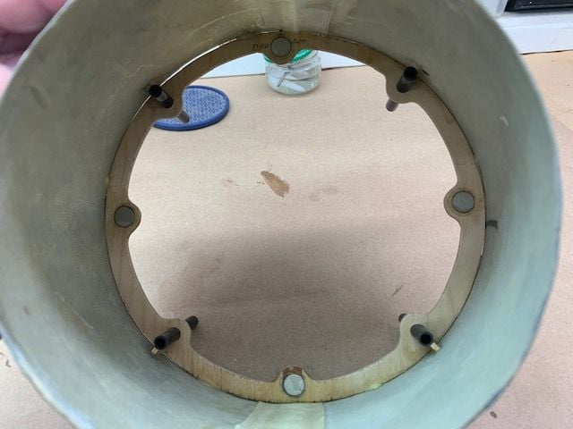
View of rear pipe holding ring from nozzle hole

Rear pipe holding ring in place on rear fuse former. All the parts were removed from fuse for paint prep.

View from turbine bay
Wood gussets installed on the nozzle former carbon tubes.

Gussets supporting nozzle former carbon tubes. Epoxy fillets applied around the former after this.

Weep holes drilled in bottom of fuse anywhere fuel or oil could puddle. Another thing I never regretted doing. I once saw a Top Gun scale jet catch fire because puddled fuel caught fire under the turbine.

I modified the fuel tray front mounts with screws to stop the movement on the front end. The Velcro strap holds the air bottles down underneath along with the fuel tray on top. Works good now.

A strip of light ply added to the bottom of the fuel tray to keep the air bottles away from the fuse former and allow space for ECU wiring under the tray to reduce the clutter on top.

All the equipment removed from fuse and wood parts ready for sealing and primer
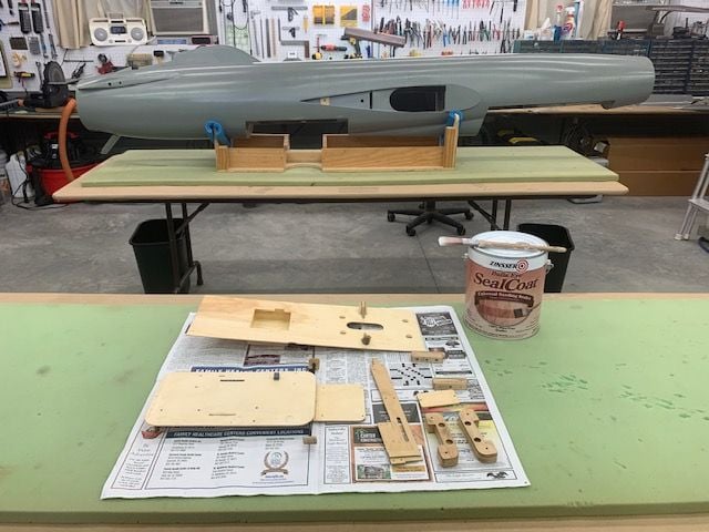
One coat of SealCoat brushed on all the wood parts and also on all the wood formers inside the fuse.
My efforts now are to get the wood parts inside the fuse fuel proofed and painted. I regretted not doing it on several jets as the wood got oil soaked. I never regretted not doing it. Besides it looks better when you take the top off.
View of rear pipe holding ring from nozzle hole
Rear pipe holding ring in place on rear fuse former. All the parts were removed from fuse for paint prep.
View from turbine bay
Wood gussets installed on the nozzle former carbon tubes.
Gussets supporting nozzle former carbon tubes. Epoxy fillets applied around the former after this.
Weep holes drilled in bottom of fuse anywhere fuel or oil could puddle. Another thing I never regretted doing. I once saw a Top Gun scale jet catch fire because puddled fuel caught fire under the turbine.
I modified the fuel tray front mounts with screws to stop the movement on the front end. The Velcro strap holds the air bottles down underneath along with the fuel tray on top. Works good now.
A strip of light ply added to the bottom of the fuel tray to keep the air bottles away from the fuse former and allow space for ECU wiring under the tray to reduce the clutter on top.
All the equipment removed from fuse and wood parts ready for sealing and primer
One coat of SealCoat brushed on all the wood parts and also on all the wood formers inside the fuse.
01-07-2021, 06:41 PM
#821
Thread Starter
My Feedback: (20)
More fuse paint prep

Not much time in shop today. Got fuel shut off valve installed.

Fuse parts with epoxy fillets, sealed, sanded, and prepped. Radio and fuel trays primed.

Started taping off fuse for spraying inside. Ran out of time here. To be continued...
Not much time in shop today. Got fuel shut off valve installed.
Fuse parts with epoxy fillets, sealed, sanded, and prepped. Radio and fuel trays primed.
Started taping off fuse for spraying inside. Ran out of time here. To be continued...
01-15-2021, 04:04 PM
#822
Thread Starter
My Feedback: (20)
Painting process

I had to pull out the spray booth and paint inside due to crummy weather. I used light grey KlassKote epoxy paint I had left over in the paint locker from the Havoc makeover last year. Parts laid out on cardboard for transport to spray booth and back.

Fuse taped up and wrapped in paper to keep finger prints and overspray off surface

Outlet from spray booth exits through slightly raised garage door
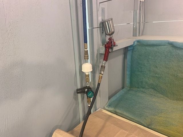
Small 4oz touch up spray gun used to get inside fuse. Water filter and regulator on air hose behind gun.

I built my portable spray booth 25 years ago when a large plane was 7' long and would fit inside. It ain't even close now, but its all I got so better than nothing.

Most of the overspray gets sucked toward the filters from the air flow so its not too bad.

Fuse done. Sheets on floor got messed around when walking around the booth.

Small parts done on clean side of cardboard
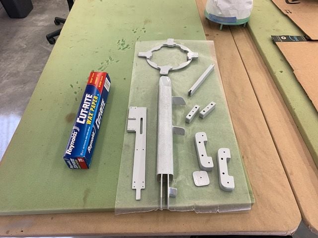
Parts curing on wax paper

I sprayed the inside of the nozzle with a dark metallic brown from rattle can
I had to pull out the spray booth and paint inside due to crummy weather. I used light grey KlassKote epoxy paint I had left over in the paint locker from the Havoc makeover last year. Parts laid out on cardboard for transport to spray booth and back.
Fuse taped up and wrapped in paper to keep finger prints and overspray off surface
Outlet from spray booth exits through slightly raised garage door
Small 4oz touch up spray gun used to get inside fuse. Water filter and regulator on air hose behind gun.
I built my portable spray booth 25 years ago when a large plane was 7' long and would fit inside. It ain't even close now, but its all I got so better than nothing.
Most of the overspray gets sucked toward the filters from the air flow so its not too bad.
Fuse done. Sheets on floor got messed around when walking around the booth.
Small parts done on clean side of cardboard
Parts curing on wax paper
I sprayed the inside of the nozzle with a dark metallic brown from rattle can
 01-15-2021, 04:14 PM
#824
Thread Starter
My Feedback: (20)
Happy snaps after paint

Nose tray

Nose gear bay

Equipment bay

Fuel tank bay

Turbine bay

Stab tray

Pipe ring
Not the real install begins!
Nose tray
Nose gear bay
Equipment bay
Fuel tank bay
Turbine bay
Stab tray
Pipe ring
Not the real install begins!
Last edited by Viper1GJ; 01-15-2021 at 04:17 PM.