


1/6 F-105 Build Thread
 09-29-2020, 05:01 PM
#751

Thread Starter
My Feedback: (20)
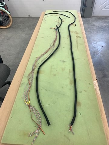
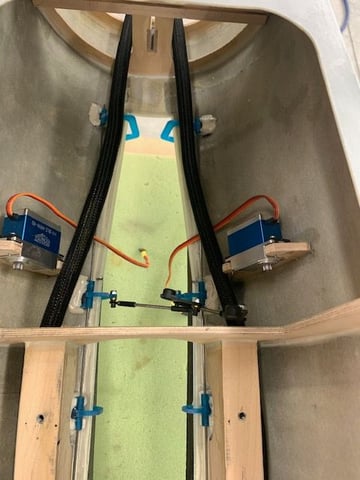
Servo wires roughed in
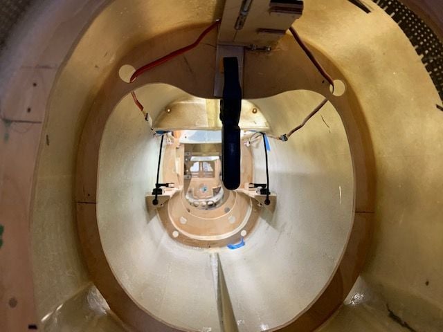
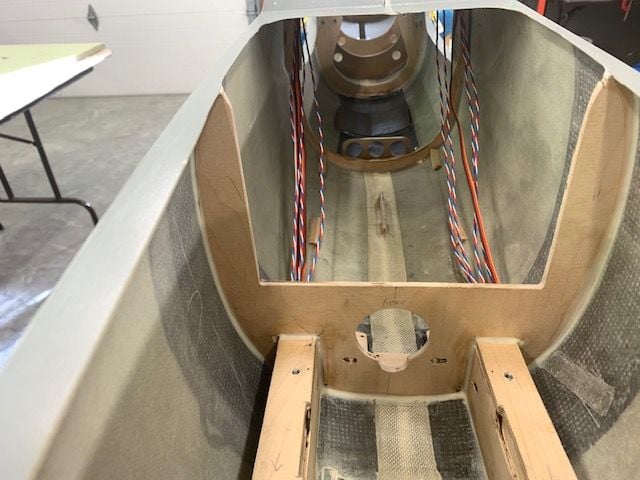
Starting from the rear the servo wires will travel forward along the top left and right of the fuse. In the final install the wires will be in flexible wire sheaths to protect from heat and chaffing

Elevator servo wires go up to the main channel and then forward

Wires come forward through the turbine formers and then through the wing former and over the wings.

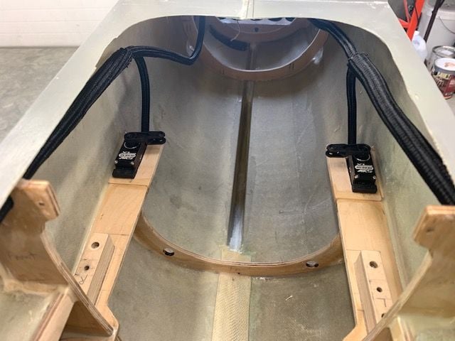
The after passing over the wings the wires will drop to the bottom of the fuse inside the air tank compartment.
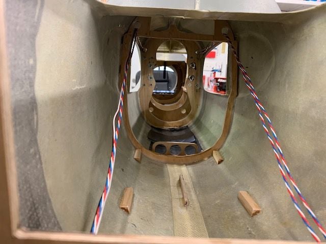
Wires will be attached to the fuse sides to allow install and removal of the fuel tank, fuel tray, and air tanks with out removing any servo wires

Wires run under the nose gear mounts and into the front compartment past the nose gear door servos. From here they will come up and over the edge of the RC equipment tray and into right and left sides of the CB400.
I ran the leads out the nose about 12" past the CB400 to make sure there is plenty of length for tucking everything in later.
Starting from the rear the servo wires will travel forward along the top left and right of the fuse. In the final install the wires will be in flexible wire sheaths to protect from heat and chaffing
Elevator servo wires go up to the main channel and then forward
Wires come forward through the turbine formers and then through the wing former and over the wings.
The after passing over the wings the wires will drop to the bottom of the fuse inside the air tank compartment.
Wires will be attached to the fuse sides to allow install and removal of the fuel tank, fuel tray, and air tanks with out removing any servo wires
Wires run under the nose gear mounts and into the front compartment past the nose gear door servos. From here they will come up and over the edge of the RC equipment tray and into right and left sides of the CB400.
I ran the leads out the nose about 12" past the CB400 to make sure there is plenty of length for tucking everything in later.
 09-29-2020, 07:34 PM
#752
My Feedback: (6)
As I take in all this engineering art, staggering in its beauty of both conception as well as execution, I must face the fact that I can scare assemble a Foam ARF! As Dirty Harry said " A man got to know his limitations" But, good on ya, Gary. Nice to sit in the Sistine Chapel of rc jets and simply stare, slack jawed, at the work of genius! I may not possess the ability to reproduce such work, but I can appreciate it!
Perhaps Shakespeare's Richard III best expressed it thusly:Cheated of feature by dissembling nature,
Deform’d, unfinish’d, sent before my time
Into this breathing world, scarce half made up,
And that so lamely and unfashionable
That dogs bark at me as I halt by them—
Sorry to wax Shakespearean, but when I am privileged to see such artful endeavors, it serves merely to remind me of my own being sent into this breathing world before my time, scarce half made up. My planes so ugly and untalented that even dogs bark their disgust at my planes on the flight line!
09-30-2020, 04:33 AM
#753
Thread Starter
My Feedback: (20)
Bone,
I appreciated and am humbled by your compliments, but what is going on here is simply kit bashing something that was created by a very talented composite fabricator. If you really want to see the "Sistine Chapel" of RC jets, just take a look at Paul creating his Buccaneer (1/7 Scale Blackburn Buccaneer All Composite Scratch Build) or Thomas creating his T-38 (1/4.5 T-38C Talon scratch build) from scratch! These guys have the real talent and skill to bring their jets to life from just ideas and they don't have to bash it to make it work.
I think my over G'd brain remembers hearing about Shakespear once in high school, but I was probably drawing airplanes on the study paper and have no idea what he said. Kudos to you for remembering!
Thanks again for your compliments
Gary
09-30-2020, 04:46 AM
#754
Thread Starter
My Feedback: (20)
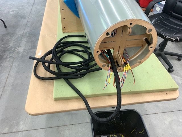
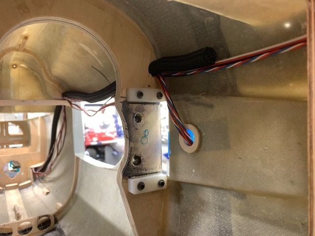
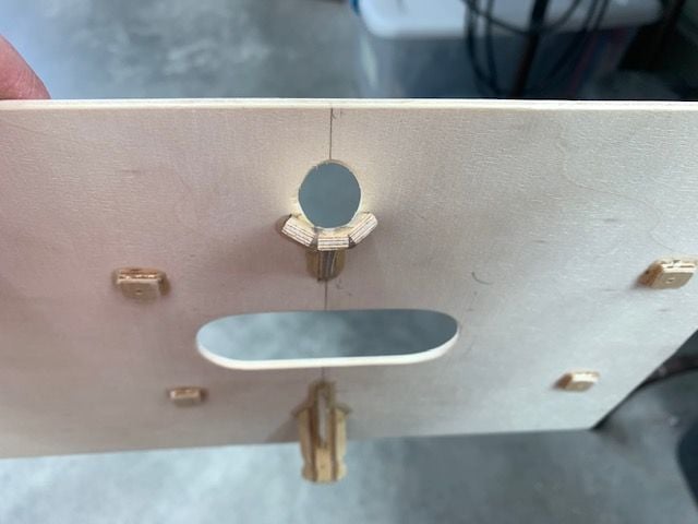
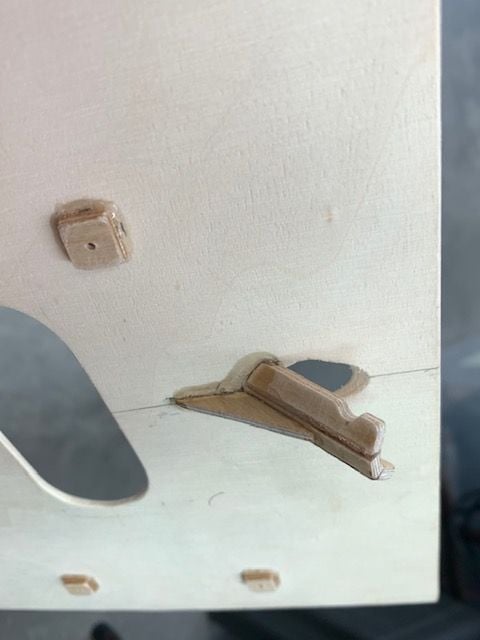
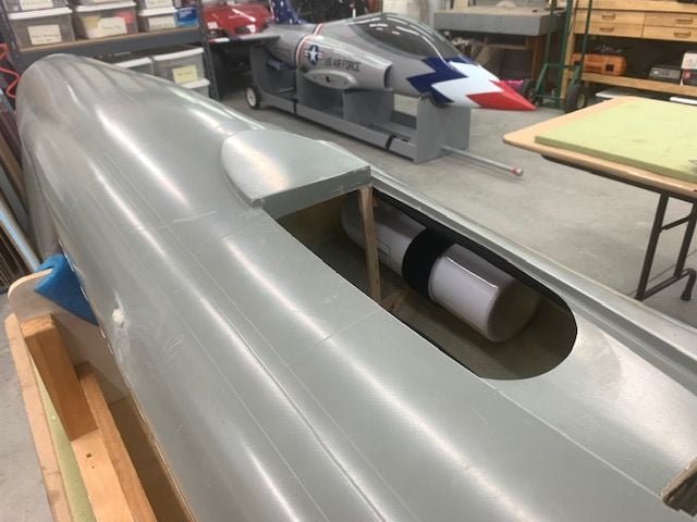
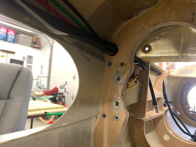
Wing wiring exit from fuse
In order to fabricate the wing servo wires I needed to figure out how they would connect to the wings and where the slack wires would go. This required putting the wings on and figuring out where the connectors would go.
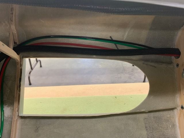
First the wing root opening was traced on the fuse side
Flap, aileron, and main gear door servo wire slack will live in the wing root with just the connector sticking out
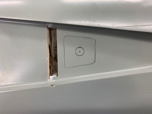
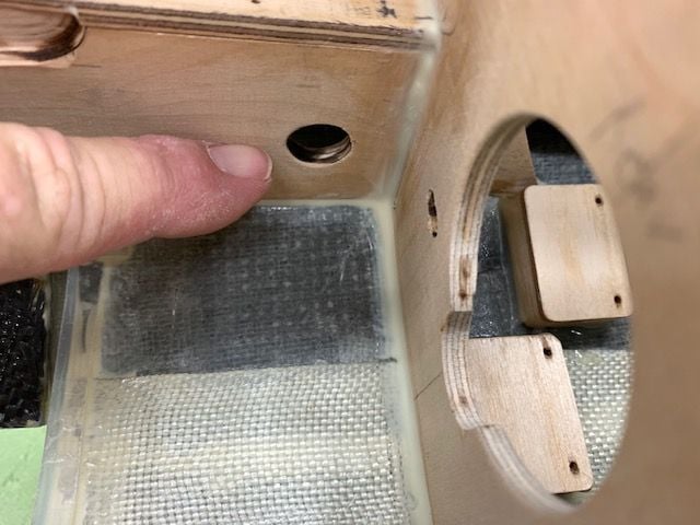
Hole marked for fuse wires to exit from
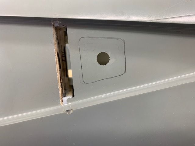
Hole cut
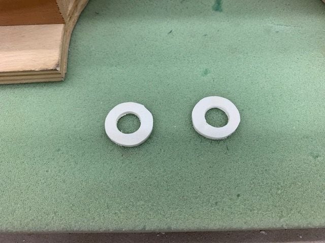
Plywood donuts made to make a smooth exit hole

Donuts glued inside fuse to take off the sharp fiberglass edge
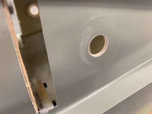
Sanding rounded off the edges to prevent cutting into the wires. Plan is to place wires inside a flexible braided sleeve at the exit hole
Planned 3 servo wing connector from Electrodynamics. Gear and brake airlines will also use this exit hole.
In order to fabricate the wing servo wires I needed to figure out how they would connect to the wings and where the slack wires would go. This required putting the wings on and figuring out where the connectors would go.
First the wing root opening was traced on the fuse side
Flap, aileron, and main gear door servo wire slack will live in the wing root with just the connector sticking out
Hole marked for fuse wires to exit from
Hole cut
Plywood donuts made to make a smooth exit hole
Donuts glued inside fuse to take off the sharp fiberglass edge
Sanding rounded off the edges to prevent cutting into the wires. Plan is to place wires inside a flexible braided sleeve at the exit hole
Planned 3 servo wing connector from Electrodynamics. Gear and brake airlines will also use this exit hole.
09-30-2020, 03:38 PM
#755
Thread Starter
My Feedback: (20)
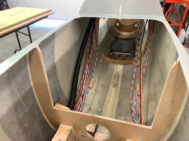
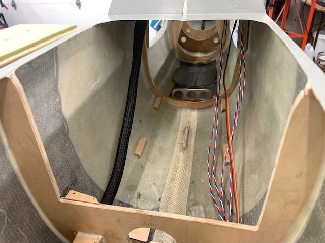
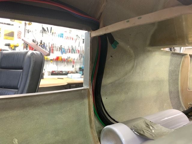
Wing servo wires roughed in

Aileron, flap, and gear door leads extended 4" out of hole for planning. These slack in these leads will be attached to the fuse inside and above the hole and connected to the 3 servo quick connect which will come out the hole.
RIght side looking forward, wing leads routed into servo wire channel over wing intake.
Servo cables dropping to bottom of fuse in air tank compartment
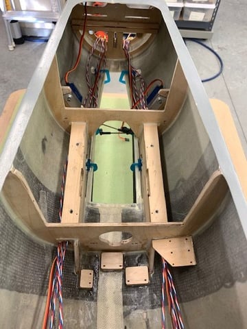
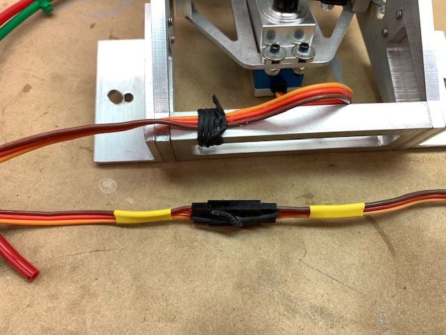
Servo leads running forward past nose gear mounts to forward section where CB 400 will be mounted on tray
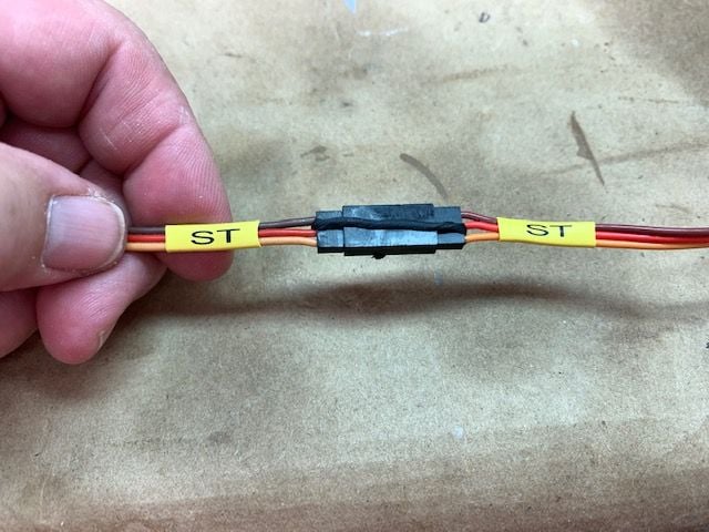
I extended the leads out the nose to ensure there is enough length to attach to CB 400 after everything is tucked in the braided flexible wire sleeves in the rear. Heat shrink labels are still loose enough to slide so they can slide back after proper length is determined and plugs attached.

I really like this Dymo Rhino 4200 label maker for the heat shrink labels. I wish I had know about it years ago.
Aileron, flap, and gear door leads extended 4" out of hole for planning. These slack in these leads will be attached to the fuse inside and above the hole and connected to the 3 servo quick connect which will come out the hole.
RIght side looking forward, wing leads routed into servo wire channel over wing intake.
Servo cables dropping to bottom of fuse in air tank compartment
Servo leads running forward past nose gear mounts to forward section where CB 400 will be mounted on tray
I extended the leads out the nose to ensure there is enough length to attach to CB 400 after everything is tucked in the braided flexible wire sleeves in the rear. Heat shrink labels are still loose enough to slide so they can slide back after proper length is determined and plugs attached.
I really like this Dymo Rhino 4200 label maker for the heat shrink labels. I wish I had know about it years ago.

The following users liked this post:
Auburn02 (10-01-2020)

The following users liked this post:
Viper1GJ (10-01-2020)
 10-01-2020, 02:01 PM
#760
Thread Starter
My Feedback: (20)
 ntn
ntnYes, I will paint the inside before I introduce any fuel or oil to the jet. I will use Klass Kote epoxy paint. Primarily to fuel proof the wood parts and 2nd for a nice look. It will look something like my Havoc here. ( I was the 3d owner here and there were 2 crashes and several internal repairs so it was pretty ugly inside.) Not sure of color yet. Possibly use the grey like the Havoc as it is the same grey on the bottom of the 105 camo scheme. Or possibly use the tan color from the camo scheme. Or maybe white. Suggestions welcome.
I plan to get everything installed and working first except for fuel and running the turbine. Then I will pull it all out and do the paint on the inside and reinstall.
Last edited by Viper1GJ; 10-01-2020 at 02:53 PM.
The following users liked this post:
skunkwurk (10-01-2020)
10-01-2020, 02:12 PM
#761
Thread Starter
My Feedback: (20)
Building first wiring harness inside the fuse
Pulling the 1/2' flex sleeve inside the fuse
Back beside wires in air tank compartment
Back to the wing hole

Start stuffing wires inside sleeve

Front compartment
Air tank compartment

Over wing

Back to wing hole

Connectors connected and looped up over the wing hole. Now 3/8" flex sleeve runs back to elevator servo

1/4" flex sleeve goes to elevator servo and chute release servo in tail

Chute release servo connected
Pulling the 1/2' flex sleeve inside the fuse
Back beside wires in air tank compartment
Back to the wing hole
Start stuffing wires inside sleeve
Front compartment
Air tank compartment
Over wing
Back to wing hole
Connectors connected and looped up over the wing hole. Now 3/8" flex sleeve runs back to elevator servo
1/4" flex sleeve goes to elevator servo and chute release servo in tail
Chute release servo connected
10-01-2020, 02:22 PM
#762
Thread Starter
My Feedback: (20)
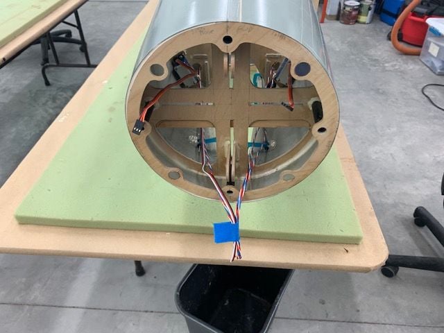
2nd wire harness made on table.
1st harness and left side wires removed from fuse to table
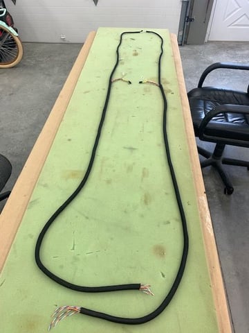
2nd wire harness made up on table. Much faster.
Both wire harness installed back into the fuse
Front compartment under the CB400

Air tank compartment

Over wings
To elevator servos

Back to chute release and rudder servos. Making the first harness inside the fuse took about 2 hours. Making the 2nd one and putting both back in took about 30 min. The harnesses will be fastened to the fuse sides with 3D printed clips once I get everything else in and figure out where the clips will go.
1st harness and left side wires removed from fuse to table
2nd wire harness made up on table. Much faster.
Both wire harness installed back into the fuse
Front compartment under the CB400
Air tank compartment
Over wings
To elevator servos
Back to chute release and rudder servos. Making the first harness inside the fuse took about 2 hours. Making the 2nd one and putting both back in took about 30 min. The harnesses will be fastened to the fuse sides with 3D printed clips once I get everything else in and figure out where the clips will go.
10-01-2020, 02:34 PM
#763
Thread Starter
My Feedback: (20)
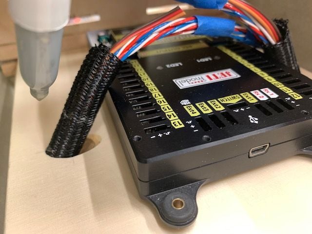
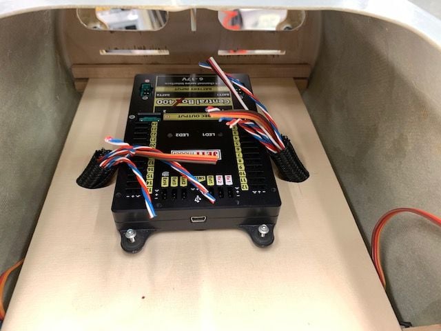
Mounting CB400
Relief cut made for nose wheel. It just barely touched so no need to build up CB400 mount
CB400 mounted to tray. Next is to plan how to run wire harness to top of tray. Since I'm making this up as it goes along I'm not sure how this will work yet. Done for the week since I have to go pay some more "RC dues" with another weekend trip.
Last edited by Viper1GJ; 10-01-2020 at 02:40 PM.
The following users liked this post:
bonefishfool (10-01-2020)
10-05-2020, 03:31 PM
#764
Thread Starter
My Feedback: (20)
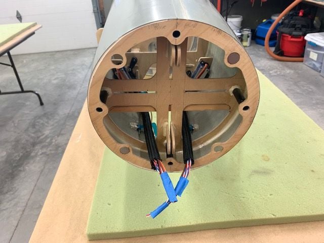
Installing harness sleeve in tray and crimping servo plugs
Taking the weekend off was good and allowed me to dream up a way to attach the wire sleeves to the tray. The design had to look good from the top, be easily removeable for service, keep the harness against the side of the fuse and away from the nose gear, be cheap, and easy to make. Here's my solution dreamed up while driving.
I made a plywood sleeve holder on a 45 degree angle with a notch to hold a wire tie or waxed lacing cord. Left side here
Right side
Marking braided sleeve for cut
Sleeves cut and wires trimmed ready for servo plug crimping
Under side of tray showing harness sleeve holder with corner gusset installed
Triangle corner gusset installed for stiffness
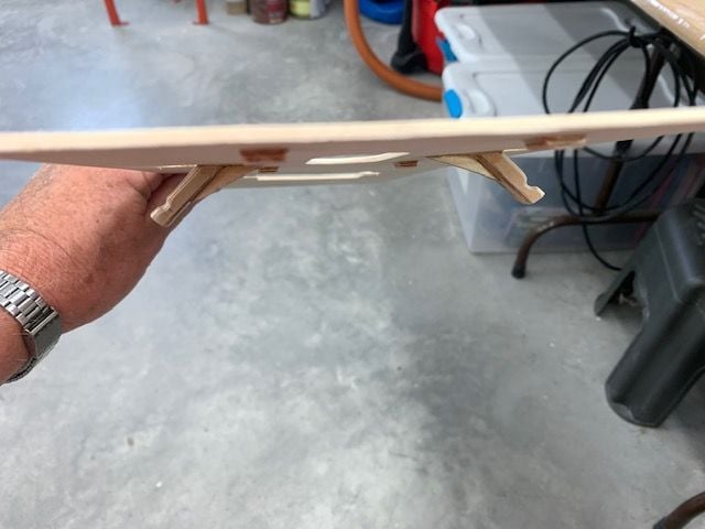
Front view. The holders keep the harness sleeve against the fuse sides and away from the nose gear. The notches are for wire ties or lacing cord tiedowns

Ready for crimping session

Plug crimps done for left side. Right side to go.
Taking the weekend off was good and allowed me to dream up a way to attach the wire sleeves to the tray. The design had to look good from the top, be easily removeable for service, keep the harness against the side of the fuse and away from the nose gear, be cheap, and easy to make. Here's my solution dreamed up while driving.
I made a plywood sleeve holder on a 45 degree angle with a notch to hold a wire tie or waxed lacing cord. Left side here
Right side
Marking braided sleeve for cut
Sleeves cut and wires trimmed ready for servo plug crimping
Under side of tray showing harness sleeve holder with corner gusset installed
Triangle corner gusset installed for stiffness
Front view. The holders keep the harness sleeve against the fuse sides and away from the nose gear. The notches are for wire ties or lacing cord tiedowns
Ready for crimping session
Plug crimps done for left side. Right side to go.

The following users liked this post:
Viper1GJ (10-05-2020)
10-06-2020, 04:22 PM
#766
Thread Starter
My Feedback: (20)
Installing wire harness

All servo plugs crimped and labeled
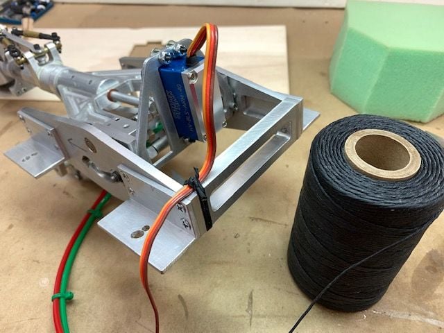
Danny from AeroPanda told me about waxed lacing cord last week. I had never seen it before. I got a spool and started trying out how to use it. There are several YT videos on how to tie different types of laces and knots. I'm liking it better than zip ties now after trying several applications. Its softer on the insulation and seems to grip very well. Thanks for the tip Danny.
Lacing cord used to secure servo extensions
Lacing cord worked well securing the steering servo wire to the nose gear frame to keep it from getting pinched when gear retracting. The zip tie I had used before was already starting to pinch the insulation. The cord is much softer and does not cut into the insulation.
I had to enlarge the holes for the air valve wires to get to the wire harness sleeve
Air valve wires tucked into the harness sleeve
Nose gear door servo wires tucked into the harness sleeve
Wire harness complete except for throttle wire from ECU
All servo plugs crimped and labeled
Danny from AeroPanda told me about waxed lacing cord last week. I had never seen it before. I got a spool and started trying out how to use it. There are several YT videos on how to tie different types of laces and knots. I'm liking it better than zip ties now after trying several applications. Its softer on the insulation and seems to grip very well. Thanks for the tip Danny.
Lacing cord used to secure servo extensions
Lacing cord worked well securing the steering servo wire to the nose gear frame to keep it from getting pinched when gear retracting. The zip tie I had used before was already starting to pinch the insulation. The cord is much softer and does not cut into the insulation.
I had to enlarge the holes for the air valve wires to get to the wire harness sleeve
Air valve wires tucked into the harness sleeve
Nose gear door servo wires tucked into the harness sleeve
Wire harness complete except for throttle wire from ECU
Last edited by Viper1GJ; 10-07-2020 at 12:04 PM.
The following users liked this post:
jsnipes (10-06-2020)
10-06-2020, 05:04 PM
#767
Thread Starter
My Feedback: (20)
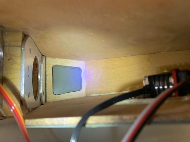
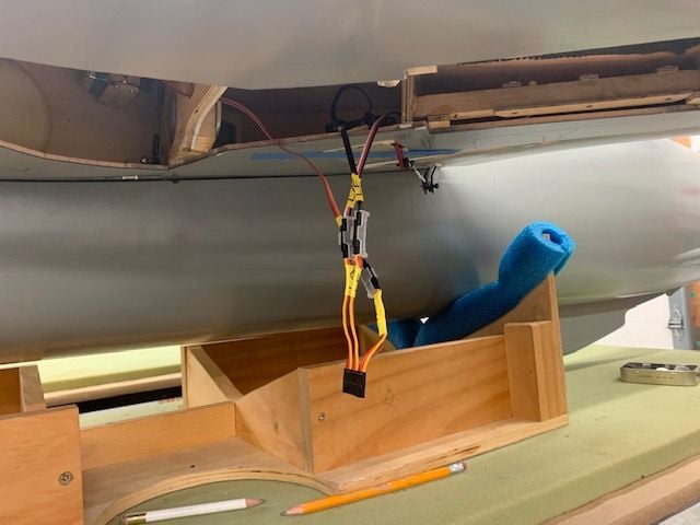
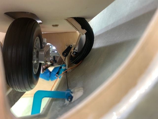
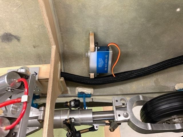
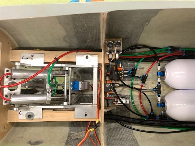
Installing air system supply lines.
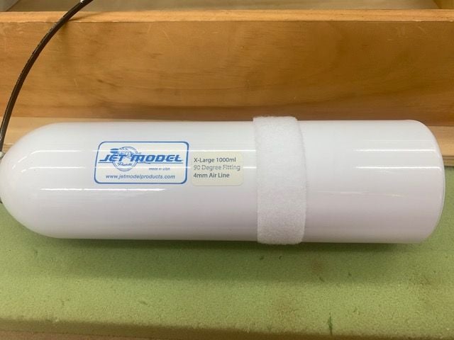
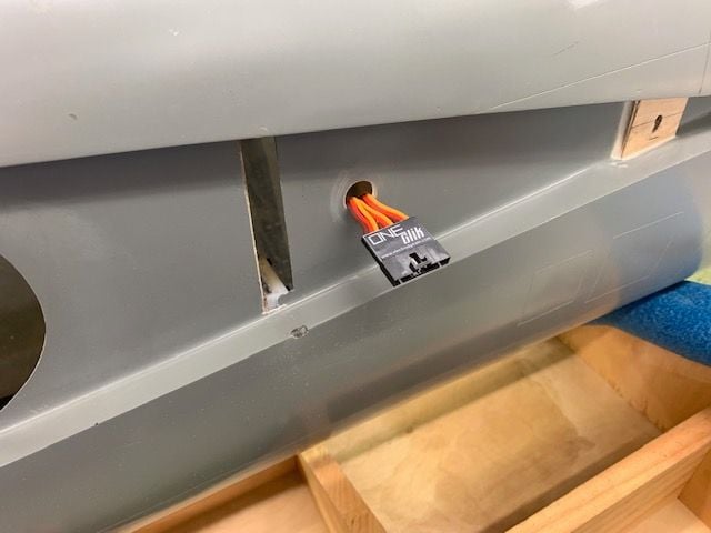
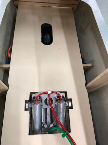
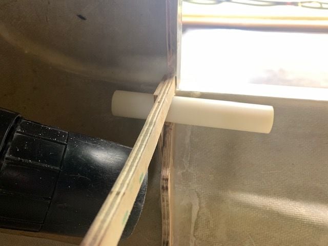
A single tank will supply air for brakes and the drag chute deploy air ram. A piece of Velcro loop is stuck to the tank to allow the black One Wrap strap to attach and not allow the tank to slip forward.
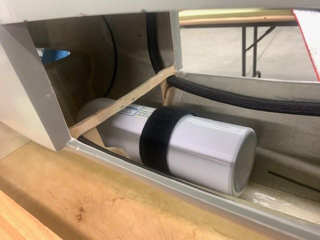
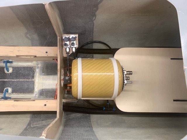
The brake tank is mounted in the top of fuse behind the cockpit. The fuse is upside down in the photo. The tank contacts the fuse top and can not slide back, the white velcro under the black strap keeps the tank from sliding forward.
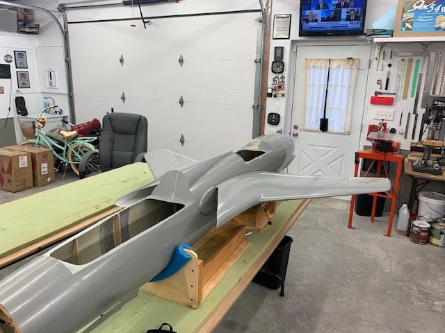
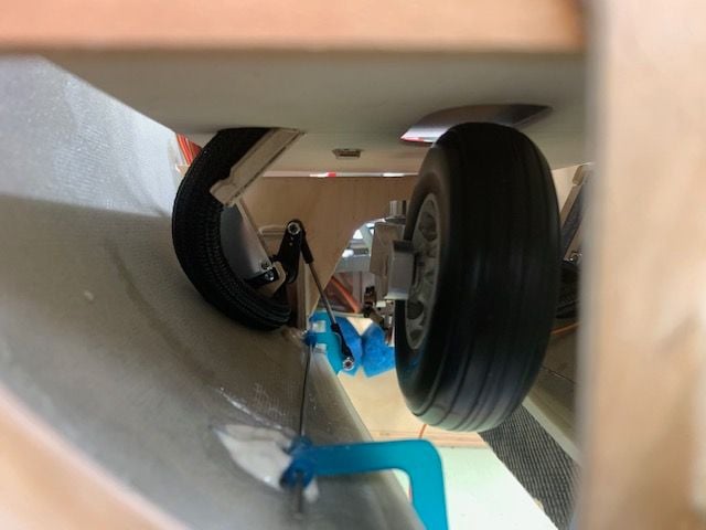
Side view of brake tank installed above fuel tank and wings. The K-320 turbine for the F-105 is currently inside the Havoc in the background. I will wait till after the SC Tiger Meet next week to pull it out and fit all the parts in.
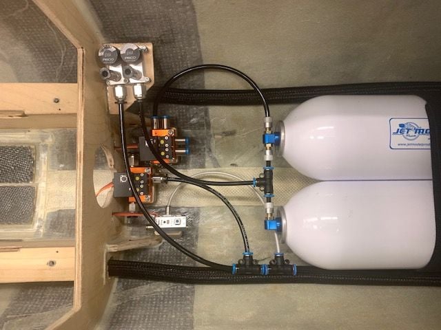
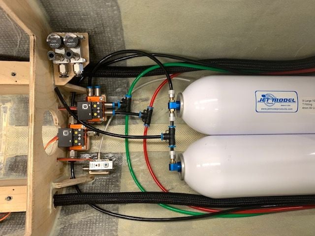
This photo took me about 2 hours to make. I forgot to write down the plan I made a few weeks ago when I glued the valve mounts in. Sooo...today I had no clue when starting to connect everything. I figured out the landing gear pretty quick but basically had to start from scratch with the brake valve and chute valve where they were. I have no clue if this is what I planned before but it seems to work ok now. The right fill valve supplies air to the 2 tanks for the landing gear system. The T between the tanks gets air from the fill valve and the air is supplied to the gear valve by the line at the top of the photo. The brake air comes from the left fill valve through the 2 T's at the bottom of the photo and then to the tank above. The first T feeds the brake valve. The second T feeds the drag chute deploy valve with a smaller 3mm line since my old Jetronics valve only has a 3mm push to connect connector.
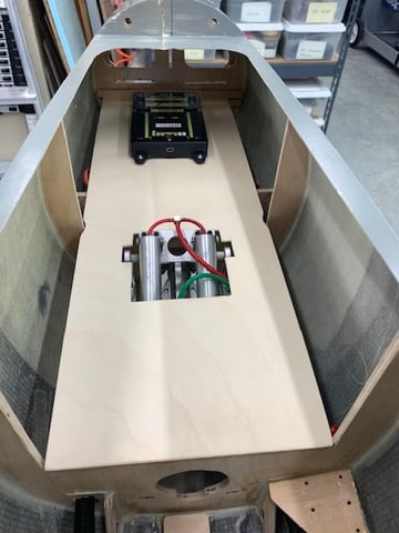
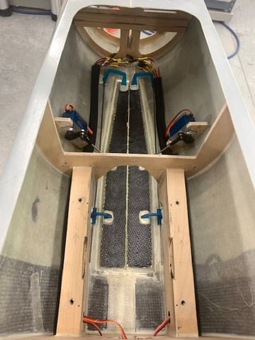
Dry fit of the fuel tray and air trap tank over the air system. It works and planned. Yea!

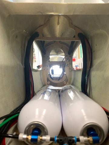
View of tanks from the nose gear area. Running the air lines to the gear and brakes is next.
A single tank will supply air for brakes and the drag chute deploy air ram. A piece of Velcro loop is stuck to the tank to allow the black One Wrap strap to attach and not allow the tank to slip forward.
The brake tank is mounted in the top of fuse behind the cockpit. The fuse is upside down in the photo. The tank contacts the fuse top and can not slide back, the white velcro under the black strap keeps the tank from sliding forward.
Side view of brake tank installed above fuel tank and wings. The K-320 turbine for the F-105 is currently inside the Havoc in the background. I will wait till after the SC Tiger Meet next week to pull it out and fit all the parts in.
This photo took me about 2 hours to make. I forgot to write down the plan I made a few weeks ago when I glued the valve mounts in. Sooo...today I had no clue when starting to connect everything. I figured out the landing gear pretty quick but basically had to start from scratch with the brake valve and chute valve where they were. I have no clue if this is what I planned before but it seems to work ok now. The right fill valve supplies air to the 2 tanks for the landing gear system. The T between the tanks gets air from the fill valve and the air is supplied to the gear valve by the line at the top of the photo. The brake air comes from the left fill valve through the 2 T's at the bottom of the photo and then to the tank above. The first T feeds the brake valve. The second T feeds the drag chute deploy valve with a smaller 3mm line since my old Jetronics valve only has a 3mm push to connect connector.
Dry fit of the fuel tray and air trap tank over the air system. It works and planned. Yea!
View of tanks from the nose gear area. Running the air lines to the gear and brakes is next.
Last edited by Viper1GJ; 10-07-2020 at 05:59 AM.
The following users liked this post:
jsnipes (10-06-2020)
10-07-2020, 04:40 PM
#771
Thread Starter
My Feedback: (20)
Installing air lines
I planned to install the air lines today but I quickly found out I made a rookie mistake when cutting the wire harness holes last week. I made them too small. I failed to take into account that the holes had to have room for the servo wire harness, three 4mm airlines, and the turbine cables with BIG plugs on each end! So the first task was to remove all the wiring and harness that were installed yesterday and enlarge the holes
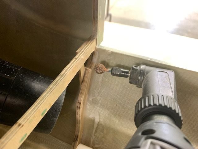
A test using a circle template showed that 3/4" diameter would probably be about the right size. I used a perma grit ball grinder to enlarge the 6 holes that had to carry more lines.
I used a 3/4" paper roller to make sure each was big enough. Then all the servo wire harness were reinstalled.
Next I installed the up and down lines to the landing gear.
The air lines basically follow the servo wire harness
Over the wing...

Then out the fuse sides

Next I installed mock up turbine ECU data and power cables. These were just used to test the install since both are too short. Longer cables are on order.
Turbine data cable runs forward over the wing

Turbine data cable shown here is too short but it will drop down to the fuel tray above the air bottles
ECU power cables on the left side. Too short here also

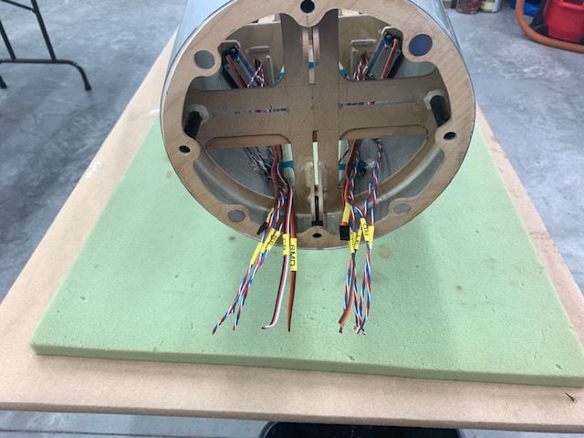
Turbine power cables run aft to turbine mount section
Then I saw I had made a big OOPS! I realized I had forgot to hook up the nose gear air lines. All I had left in 4mm fittings were two Y connectors so I used them to hook up the nose gear lines. I am not happy with this so I ordered two 4mm 4 way fittings from Aeropanda that will replace the T fittings and feed the nose, and both right and left mains from the same 4 way fitting. I'll fix this when the fittings arrive.
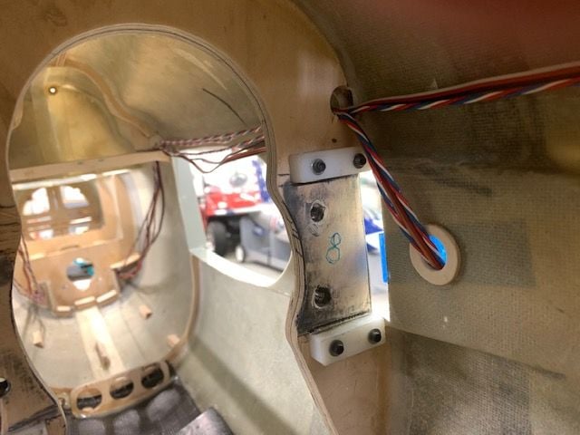
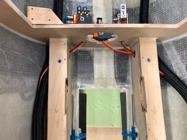
I decided to use 4 screws instead of just 2 screws on the electronics tray because the middle of the tray was a little flexible. Small blocks of basswood were glued to the nose gear formers for mounting screws.
I will probably mount the Cortex gyro near the forward screws like shown here. The 2 forward screws make the tray much more stiff in the middle than before.
I planned to install the air lines today but I quickly found out I made a rookie mistake when cutting the wire harness holes last week. I made them too small. I failed to take into account that the holes had to have room for the servo wire harness, three 4mm airlines, and the turbine cables with BIG plugs on each end! So the first task was to remove all the wiring and harness that were installed yesterday and enlarge the holes
A test using a circle template showed that 3/4" diameter would probably be about the right size. I used a perma grit ball grinder to enlarge the 6 holes that had to carry more lines.
I used a 3/4" paper roller to make sure each was big enough. Then all the servo wire harness were reinstalled.
Next I installed the up and down lines to the landing gear.
The air lines basically follow the servo wire harness
Over the wing...
Then out the fuse sides
Next I installed mock up turbine ECU data and power cables. These were just used to test the install since both are too short. Longer cables are on order.
Turbine data cable runs forward over the wing
Turbine data cable shown here is too short but it will drop down to the fuel tray above the air bottles
ECU power cables on the left side. Too short here also
Turbine power cables run aft to turbine mount section
Then I saw I had made a big OOPS! I realized I had forgot to hook up the nose gear air lines. All I had left in 4mm fittings were two Y connectors so I used them to hook up the nose gear lines. I am not happy with this so I ordered two 4mm 4 way fittings from Aeropanda that will replace the T fittings and feed the nose, and both right and left mains from the same 4 way fitting. I'll fix this when the fittings arrive.
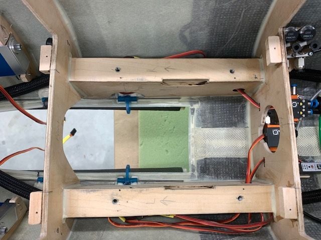
I decided to use 4 screws instead of just 2 screws on the electronics tray because the middle of the tray was a little flexible. Small blocks of basswood were glued to the nose gear formers for mounting screws.
I will probably mount the Cortex gyro near the forward screws like shown here. The 2 forward screws make the tray much more stiff in the middle than before.
The following 2 users liked this post by Viper1GJ:
bonefishfool (10-08-2020),
jsnipes (10-08-2020)

 incredible build thank you
The following users liked this post:
Viper1GJ (10-08-2020)
10-08-2020, 04:30 PM
#774
Thread Starter
My Feedback: (20)
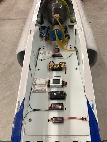
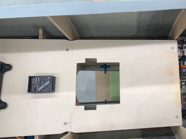
Electronics layout

Not much shop time today. Tried to do some electronics layout planning. Spent about an hour staring in the hole trying different positions for everything. I finally came up with this as a first cut. The traditional method of stuff mounted on top of tray with wires underneath will not work here because the nose gear and gear doors are under the tray and would foul the wires. So some wires will be on top of tray. Also I wanted to minimize the number of disconnections needed to remove the tray which led to the idea mounting the receivers on the tray with wires on top so they don't have to be disconnected to remove the tray.
I think the batteries will be mounted in the nose cone. Not sure yet but guessing I will need most weight in front.
The CB 400 is mounted forward of the cockpit for weight and height so the plugs will clear the cockpit tub.
The RC switch receiver is mounted on top of the CB400 like Alex did in the F2Y Sea Dart thread. The antennas will be on each side of the CB400.
The Cortex Pro is behind the CB400 where the tray is stiff between the forward screws. Short jumper connectors will connect to the CB400.
The two 2.4 receivers are next on each side of the tray. The primary receiver is on the right. The wires to the Cortex Pro will be mounted on top of the tray. The antennas will attach to the forward and aft fuse sides and mount 90 degrees to each other away from the carbon fiber.
The CTU is center aft. A short jumper will connect the CTU to the primary 2.4 receiver. The GSU lead from the ECU will come in from the left in the servo harness.
The backup 900mhz receiver is mounted on the left fuse side. The connector will go to the CB400 in the servo harness. The 900 blade antennas will go aft and be mounted 90 degrees to each other on the fuse side and up behind the cockpit turtle deck.
The ECU will be on the back of the fuel system tray with leads from the turbine coming in from each side. The throttle wire will run to the CB400 inside the right servo harness.
In theory I should only have to remove antennas of the 2.4 receivers from the fuse sides to pull the tray up as long as you could leave all leads plugged into the CB400 from the two sleeved harness cables. I think...we will see.
The following users liked this post:
jsnipes (10-08-2020)
10-08-2020, 05:33 PM
#775
Thread Starter
My Feedback: (20)
CB400 Mapping
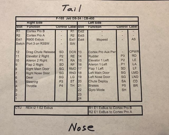
I always plan a mapping chart for the servo wires based on the layout in the fuse and the placement of the CB400. In this case it's mostly left and right, tail to nose with the exception of the Cortex Pro aux power lead. This always gets changed as the install progresses but its a first plan. When its done I print it out small and laminate with packing tape and mount it inside the fuse. A year from now a the field when I need to fix something I will be able to see what I did a year earlier.
I always plan a mapping chart for the servo wires based on the layout in the fuse and the placement of the CB400. In this case it's mostly left and right, tail to nose with the exception of the Cortex Pro aux power lead. This always gets changed as the install progresses but its a first plan. When its done I print it out small and laminate with packing tape and mount it inside the fuse. A year from now a the field when I need to fix something I will be able to see what I did a year earlier.
Last edited by Viper1GJ; 10-09-2020 at 03:47 PM.
The following users liked this post:
bonefishfool (10-08-2020)