


1/6 F-105 Build Thread

 09-18-2020, 02:49 PM
#727

I would have to pull my radio out and look through the screens to remember exactly how I did it, but it was a mix to provide a percentage of left or right travel when the gear switch was in a up position. His nose wheel was hitting the cockpit tub. I was able to offset the wheel a few degrees to clear the bottom of the tub. Also, if needed, you should be able to add a slight delay to allow it to clear the fuse on the way up before it offsets. Does that make sense? I can set it up on the bench and send you a video of the setup and it working with a spare servo if you see merit. Just let me know, glad to help.
09-19-2020, 03:55 PM
#730

Thread Starter
My Feedback: (20)
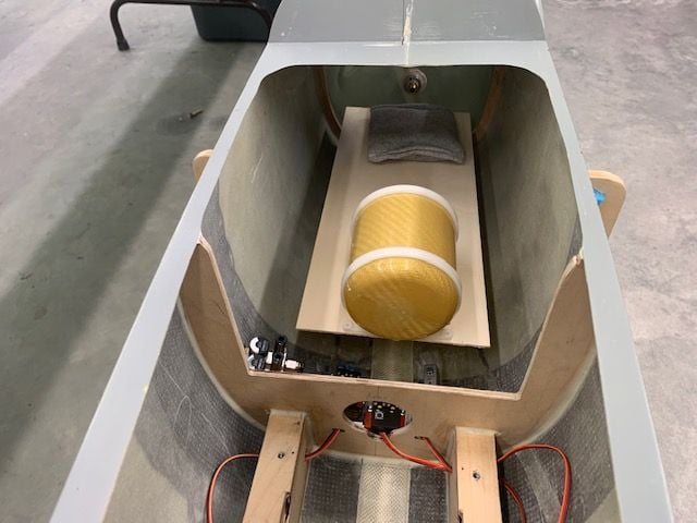
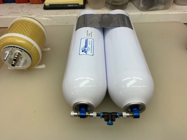
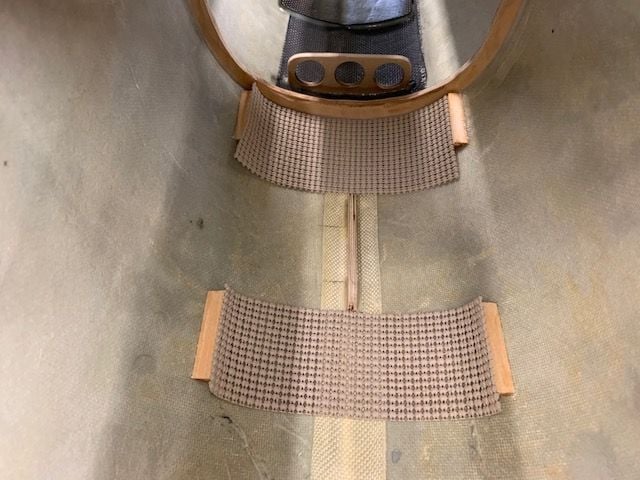
Mounting air valves
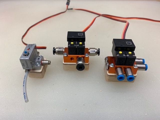
Air valve mounts made from balsa and plywood
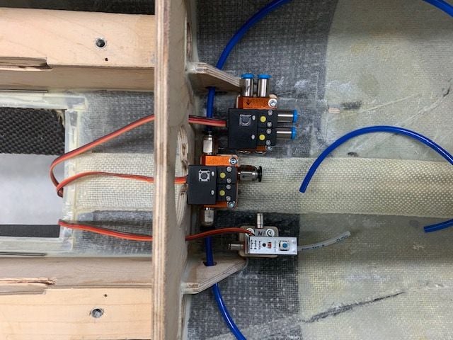
After lots of planning for where lines and wires would go this was the final line up. Gear valve on top, brakes in middle, and drag chute on bottom. Holes were cut in formers for tube and wire routing
Wires for valves and nose gear steering routed to sides to go forward to CB400
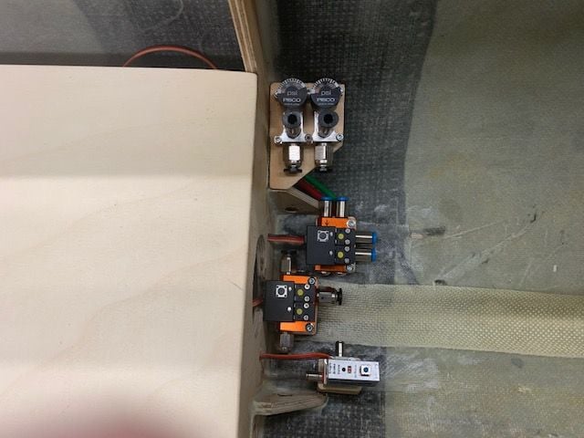
Air fill valves and gauges from Ultimate Jets mounted on side with a slight angle to make it easier for getting my fat fingers in there and seeing the gauges from the side
Air valve mounts made from balsa and plywood
After lots of planning for where lines and wires would go this was the final line up. Gear valve on top, brakes in middle, and drag chute on bottom. Holes were cut in formers for tube and wire routing
Wires for valves and nose gear steering routed to sides to go forward to CB400
Air fill valves and gauges from Ultimate Jets mounted on side with a slight angle to make it easier for getting my fat fingers in there and seeing the gauges from the side
Last edited by Viper1GJ; 09-19-2020 at 04:18 PM.
09-19-2020, 04:17 PM
#731
Thread Starter
My Feedback: (20)
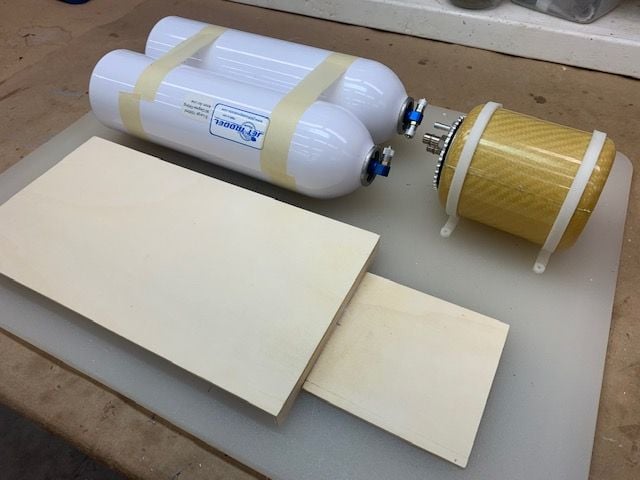
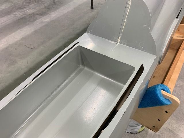
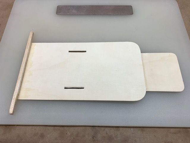
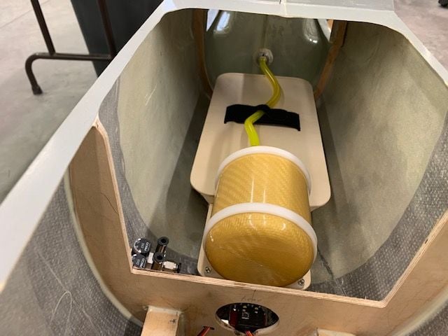
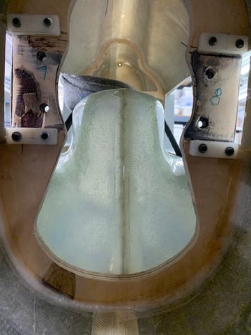
Making fuel system tray
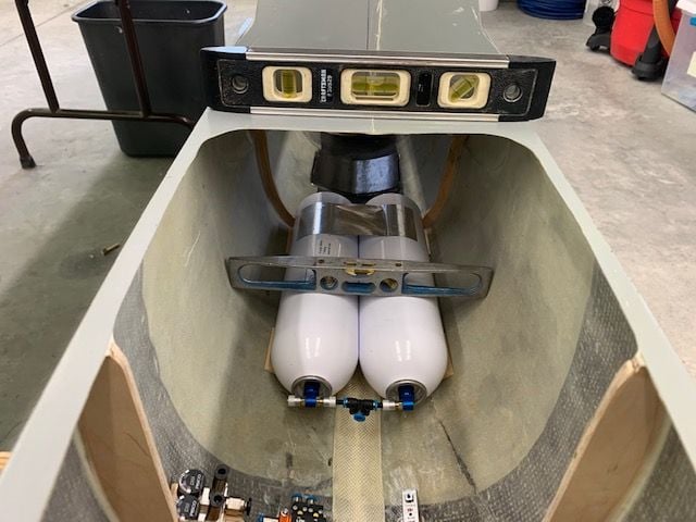
First look at fuel system tray. The concept here is to make a fuel system tray that will hold the air trap tank, pump, filter, and ECU. It should be removeable along with the fuel tank by unfastening the Velcro straps and disconnecting the turbine fuel line at the fuel cutoff valve above the turbine.
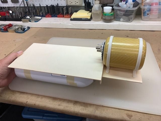
The air trap tank is too high and bumps into the cockpit tub.
Fix is to drop the air trap tank low enough to clear the cockpit tub but not interfere with the air valves and tubes
Install concept
Cockpit tub fits good now
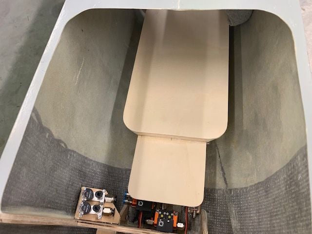
Trimmed up tray to look nice
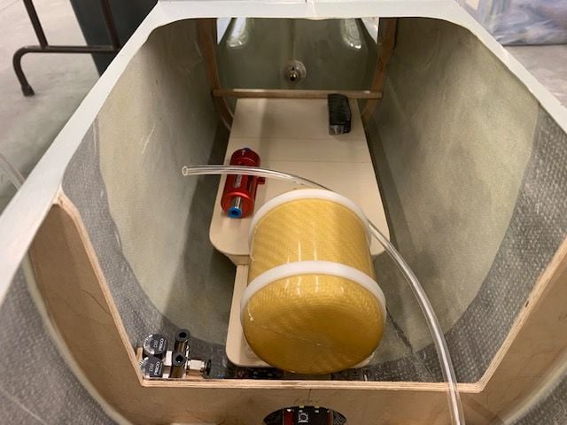
Planning the fuel tray layout with tubing. Initial plan is to mount the ECU on aft left in photo. Pump will be in aft right of photo where the black weight is. Filter is on the front left. The fuel will run from tank outlet to top of air trap tank. Then from center of air trap to pump. Then out the pump outlet with a loop around to connect to front of filter, then out rear to the fuel cut off valve and then to the turbine. Tray will be held on top of the air tanks with the Velcro strap in the middle, not yet in this photo.
First look at fuel system tray. The concept here is to make a fuel system tray that will hold the air trap tank, pump, filter, and ECU. It should be removeable along with the fuel tank by unfastening the Velcro straps and disconnecting the turbine fuel line at the fuel cutoff valve above the turbine.
The air trap tank is too high and bumps into the cockpit tub.
Fix is to drop the air trap tank low enough to clear the cockpit tub but not interfere with the air valves and tubes
Install concept
Cockpit tub fits good now
Trimmed up tray to look nice
Planning the fuel tray layout with tubing. Initial plan is to mount the ECU on aft left in photo. Pump will be in aft right of photo where the black weight is. Filter is on the front left. The fuel will run from tank outlet to top of air trap tank. Then from center of air trap to pump. Then out the pump outlet with a loop around to connect to front of filter, then out rear to the fuel cut off valve and then to the turbine. Tray will be held on top of the air tanks with the Velcro strap in the middle, not yet in this photo.
Last edited by Viper1GJ; 09-19-2020 at 04:22 PM.
09-19-2020, 06:41 PM
#732
Mounting air valves
Air valve mounts made from balsa and plywood
After lots of planning for where lines and wires would go this was the final line up. Gear valve on top, brakes in middle, and drag chute on bottom. Holes were cut in formers for tube and wire routing
Wires for valves and nose gear steering routed to sides to go forward to CB400
Air fill valves and gauges from Ultimate Jets mounted on side with a slight angle to make it easier for getting my fat fingers in there and seeing the gauges from the side
Last edited by skunkwurk; 09-20-2020 at 04:43 AM.
09-20-2020, 05:14 AM
#733
Thread Starter
My Feedback: (20)
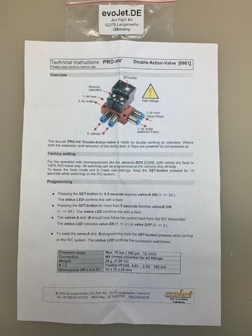
I got them from Ultimate Jets here:
https://www.ultimate-jets.net/collec...ion-gear-valve
It looks like they come from EvoJet in Germany. I wanted the 4mm push to connect fittings for the hi flow air system to the gear. All my lines were planned to be 4mm but I will have to use a reducer at the gear. I used a Jetronics brake valve I already had for the chute because I could not get the EvoJet brake valve to work in non proportional mode. It should be great for pneumatic brakes.
09-20-2020, 05:19 AM
#734
I got them from Ultimate Jets here:
https://www.ultimate-jets.net/collec...ion-gear-valve
It looks like they come from EvoJet in Germany. I wanted the 4mm push to connect fittings for the hi flow air system to the gear. All my lines were planned to be 4mm but I will have to use a reducer at the gear. I used a Jetronics brake valve I already had for the chute because I could not get the EvoJet brake valve to work in non proportional mode. It should be great for pneumatic brakes.
https://www.ultimate-jets.net/collec...ion-gear-valve
It looks like they come from EvoJet in Germany. I wanted the 4mm push to connect fittings for the hi flow air system to the gear. All my lines were planned to be 4mm but I will have to use a reducer at the gear. I used a Jetronics brake valve I already had for the chute because I could not get the EvoJet brake valve to work in non proportional mode. It should be great for pneumatic brakes.
Thank you for sharing!
09-20-2020, 03:36 PM
#735
Thread Starter
My Feedback: (20)
Installing the fuel system tray
Slots cut in tray for Velcro strap
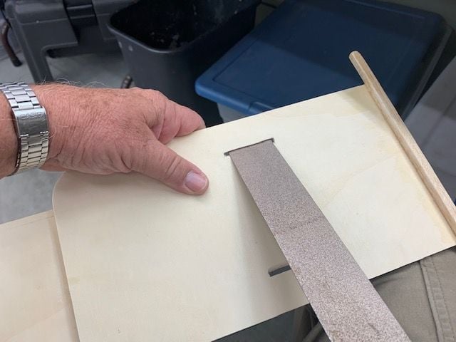
Slot edges angled for strap to fit around air tanks with flat permagrit file
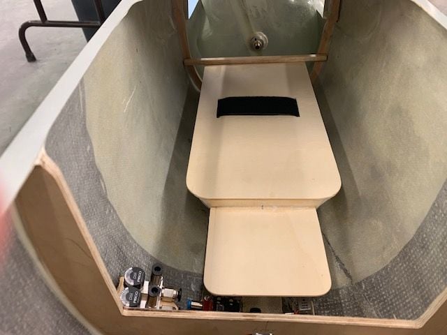
Tray installed
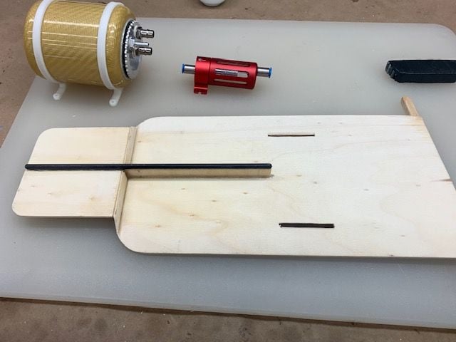
Carbon fiber tube glued under tray to provide support for air trap tank
Festo Tee between tanks goes to fill valve. Landing gear valve will get air from the left fitting. HVAC aluminum tape holding tanks together in back.
Bubble levels used to level fuse and air tanks before tank holders glued in place
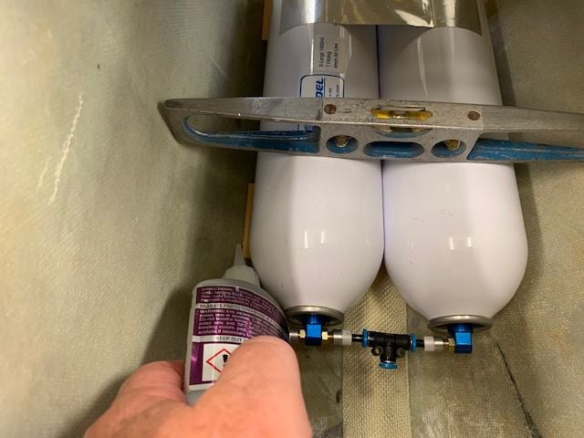
Tack gluing in tank holders
Tanks removed and holders securely glued in place.
Drawer lining material under tanks helps keep them from moving when strapped down
Air trap tank screwed to tray and main fuel line from main tank roughed in. Small Velcro strap used to hold fuel line to main strap. Once everything is in I will trim the fuel line to proper length. I removed the stick from the back of the tray since it wasn't doing much after I cut the slots for the strap. I think once the tray gets loaded up with stuff and air trap tank full of fuel I will have to fasten it to the fuse sides. The strap does not really keep the air trap tank from moving laterally like I had planned at first. Fuel vent install next.
Slots cut in tray for Velcro strap
Slot edges angled for strap to fit around air tanks with flat permagrit file
Tray installed
Carbon fiber tube glued under tray to provide support for air trap tank
Festo Tee between tanks goes to fill valve. Landing gear valve will get air from the left fitting. HVAC aluminum tape holding tanks together in back.
Bubble levels used to level fuse and air tanks before tank holders glued in place
Tack gluing in tank holders
Tanks removed and holders securely glued in place.
Drawer lining material under tanks helps keep them from moving when strapped down
Air trap tank screwed to tray and main fuel line from main tank roughed in. Small Velcro strap used to hold fuel line to main strap. Once everything is in I will trim the fuel line to proper length. I removed the stick from the back of the tray since it wasn't doing much after I cut the slots for the strap. I think once the tray gets loaded up with stuff and air trap tank full of fuel I will have to fasten it to the fuse sides. The strap does not really keep the air trap tank from moving laterally like I had planned at first. Fuel vent install next.
09-21-2020, 02:35 PM
#736
Thread Starter
My Feedback: (20)
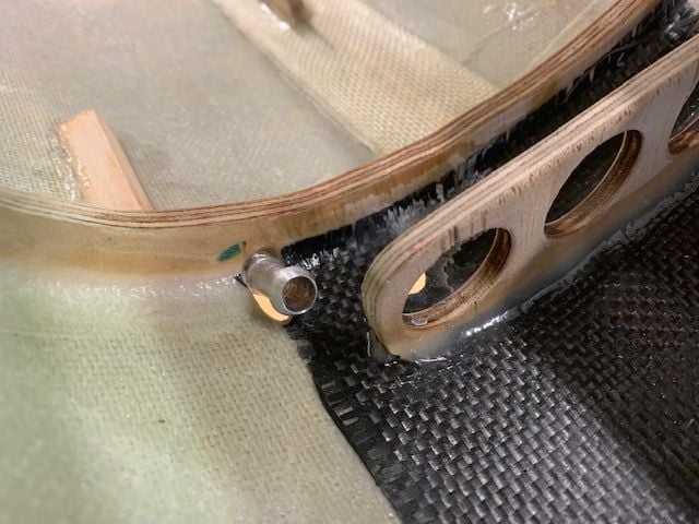
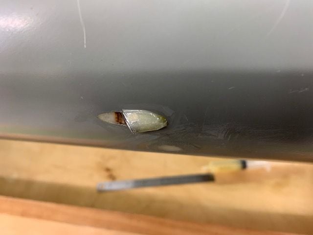
Fuel tank vent installed
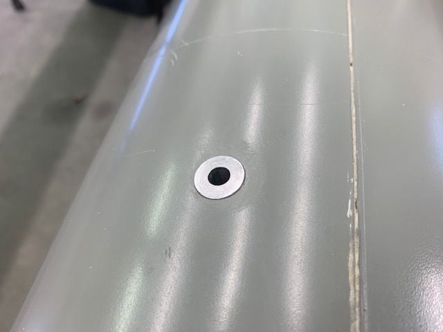
1/4" ID flush vent fitting from Ultimate Jets tack glued in place slightly to left of centerline and just forward of wing leading edge so you can reach it from the left side.
Installed between former and forward tank stop worked out good. Does not interfere with moving tank in and out. I'll put some epoxy around the base later.
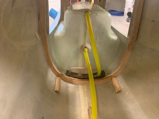
Fuel tank vent tubing roughed in.
Spent the rest of the day doing maintenance on the 1/5th F-16 and installing a CB 200 back in the Havoc so I can have something to fly at the SC Tiger Meet in October.
1/4" ID flush vent fitting from Ultimate Jets tack glued in place slightly to left of centerline and just forward of wing leading edge so you can reach it from the left side.
Installed between former and forward tank stop worked out good. Does not interfere with moving tank in and out. I'll put some epoxy around the base later.
Fuel tank vent tubing roughed in.
Spent the rest of the day doing maintenance on the 1/5th F-16 and installing a CB 200 back in the Havoc so I can have something to fly at the SC Tiger Meet in October.
The following users liked this post:
bonefishfool (09-21-2020)

The following users liked this post:
skunkwurk (09-21-2020)
09-22-2020, 06:14 AM
#740
Thread Starter
My Feedback: (20)
I was going to use just a clump of Six10 epoxy but the plywood ring is a great idea. It's really hard to get the 1/4" ID Tygon over the barbed nipple on these fittings that I've used in the past and it can really put stress on the joint and fitting. I actually put the fitting on a 1/4" drill bit and ran the drill to sand the edge off the barb a little to make it easier to get tubing over the barb (and to help get it off later).
I like the idea of the ply ring. I'll use it and the epoxy together and it will be much stronger. Thanks for the idea. I really appreciate all the eye's helping me on this project. Hopefully it will keep me from doing something stupid.
Thanks again,
Gary
I like the idea of the ply ring. I'll use it and the epoxy together and it will be much stronger. Thanks for the idea. I really appreciate all the eye's helping me on this project. Hopefully it will keep me from doing something stupid.
Thanks again,
Gary
09-22-2020, 07:29 AM
#741

Gary,
Rather than plywood for the vent support, I would recommend using thick G-10. I used plywood on my Hunter, but overtime there is a slow seepage of fuel from the vent and it soaks into the wood, even if it was notionally sealed with epoxy.
On my Buccaneer, I am at that stage also with the install, and I plan on using 3mm thick G-10 as the vent doubler/ mount.
Paul
 09-22-2020, 05:00 PM
#744
Thread Starter
My Feedback: (20)
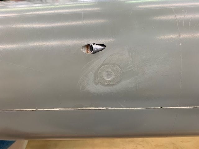
Rav, Great idea. Here is how I installed the same fitting last summer in the bottom of my Havoc. It works just like the forward scoop vents and there is no fuel streaming out. So why did I not install the one in the F-105 the same way. Like I said in the above post, I did something stupid...I forgot about it! Aaaargh! If I can get it out I will reinstall it at a forward angle. Maybe I can soften the CA with some solvent and pop it out. We will see. Thanks for the tip again.
G
 09-24-2020, 03:44 PM
#747
Thread Starter
My Feedback: (20)
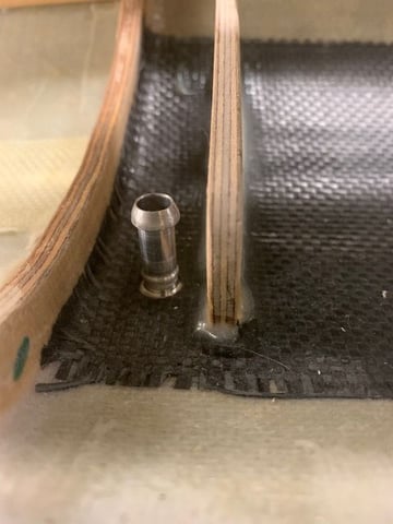
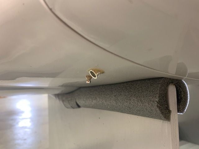
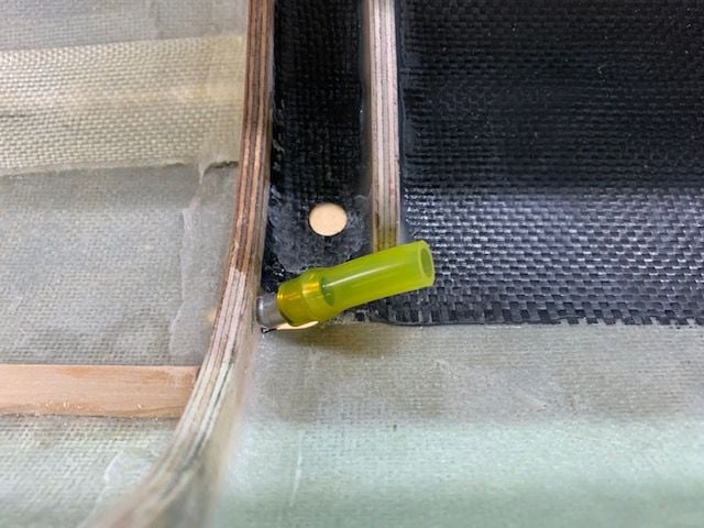
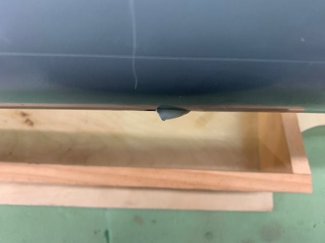
Prepping vent fitting for install as a forward facing scoop vent.
Getting the fitting out was not a problem. It was just tack glued in with thin CA. I dropped some acetone on it from inside and outside and it popped out easy with a knife blade under the flange. I then soaked it in acetone to get all the CA residue off.
Used a screwdriver with a small drill bit to get an angled hole started next to the former. I planned to use the former to stiffen the fitting install with epoxy.
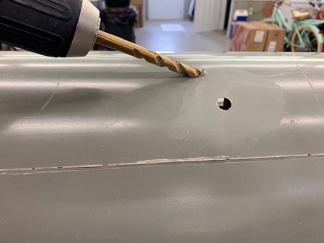
Enlarged the hole from the outside with a drill. Then made final cuts with a perma grit round file.
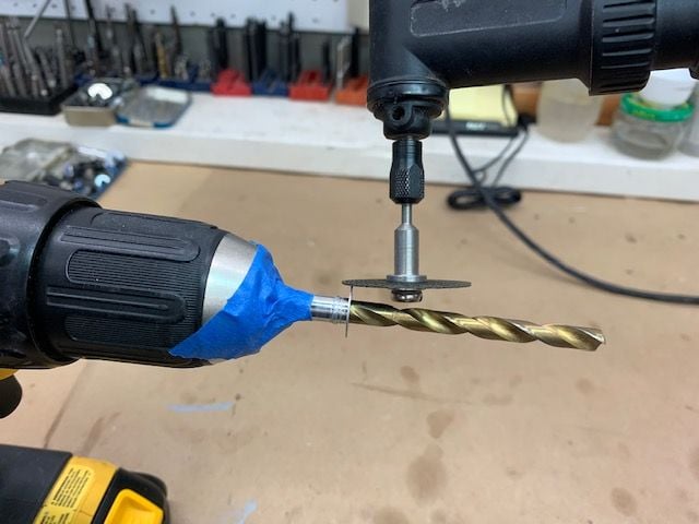
Ground the flange off the fitting with my "high tech" CNC (Central Nervous Controlled) lathe and cutter. I taped the fitting to the bit to keep it from slipping when touching the cut off wheel to the flange.
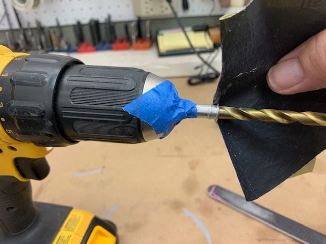
A high end scuff finish to allow epoxy to grip the fitting.
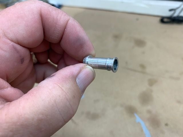
All done ready to install
Getting the fitting out was not a problem. It was just tack glued in with thin CA. I dropped some acetone on it from inside and outside and it popped out easy with a knife blade under the flange. I then soaked it in acetone to get all the CA residue off.
Used a screwdriver with a small drill bit to get an angled hole started next to the former. I planned to use the former to stiffen the fitting install with epoxy.
Enlarged the hole from the outside with a drill. Then made final cuts with a perma grit round file.
Ground the flange off the fitting with my "high tech" CNC (Central Nervous Controlled) lathe and cutter. I taped the fitting to the bit to keep it from slipping when touching the cut off wheel to the flange.
A high end scuff finish to allow epoxy to grip the fitting.
All done ready to install
09-24-2020, 04:42 PM
#748
Thread Starter
My Feedback: (20)
Installing forward facing fuel vent
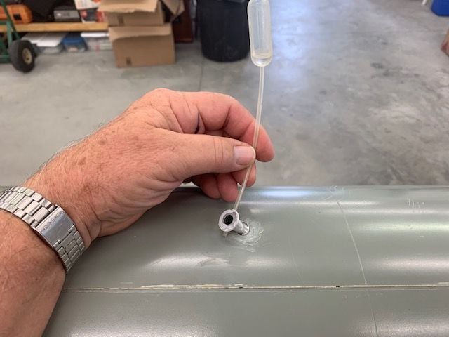
Vent fitting tack glued in place with thin and then medium CA
CA glued from outside. First hole patched with 3 oz fiberglass and thin CA
1/4" ID Tygon coated on inside and outside with Vaseline as a release agent slipped over fitting to make sure the epoxy did not cure on the fitting blocking the tubing from sliding over it later
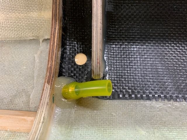
Six10 epoxy applied around fitting and to former to help make a strong joint. It can take some force to get the tubing over the fitting barb so I did not want it to pop off. First hole back filled with epoxy.
Outside epoxy was somewhat shaped to fair the fitting into the fuse belly
SIde view
Front view. If I was a air molecule approaching at 100mph I think I could smash myself into the hole and then help pressurize the fuel tank. At least that's the idea. Works pretty good on my Havoc.
Vent fitting tack glued in place with thin and then medium CA
CA glued from outside. First hole patched with 3 oz fiberglass and thin CA
1/4" ID Tygon coated on inside and outside with Vaseline as a release agent slipped over fitting to make sure the epoxy did not cure on the fitting blocking the tubing from sliding over it later
Six10 epoxy applied around fitting and to former to help make a strong joint. It can take some force to get the tubing over the fitting barb so I did not want it to pop off. First hole back filled with epoxy.
Outside epoxy was somewhat shaped to fair the fitting into the fuse belly
SIde view
Front view. If I was a air molecule approaching at 100mph I think I could smash myself into the hole and then help pressurize the fuel tank. At least that's the idea. Works pretty good on my Havoc.
09-28-2020, 05:26 PM
#749
Thread Starter
My Feedback: (20)
The reinstall of the fuel vent came out OK and I'm happy with it now. Thanks for reminder to make it forward facing.
I had planned on laying out the fuel system components and plumbing this week but that required removing the turbine system from my Havoc to have the parts available to work with. Today, I decided not to take the turbine, ECU, and pump out of the Havoc until after the SC Tiger Meet in October so I could still fly it then. So, I started making the longest servo leads for the rudder and drag chute release. I'm using Powerbox Maxi wire for all flight controls and regular servo wire for the drag chute release. I immediately ran into a problem when routing the wires from the tail to the nose.
Two years ago when designing the formers I made holes for routing the servo and turbines wires along the bottom sides of the fuse in a traditional way just assuming it would be easy. Last spring when I made the fuel tank I made it too big and failed to leave room for the wiring beside the tank. The tank is now wide enough that it blocks the wire paths on both sides at the bottom of the fuse.
My plan now is to run the servo wires on the top sides of the fuse and over the wing openings. This is probably a better route anyway because the wires from the tail start at the top of the fuse and the new channels will be over the tank and out of the way of wing mounting screws. This will all be OK except there are no holes in the formers. So I will have to spend a day making new holes for wires and planning how to keep them away from the turbine and moving parts. Just another chapter...
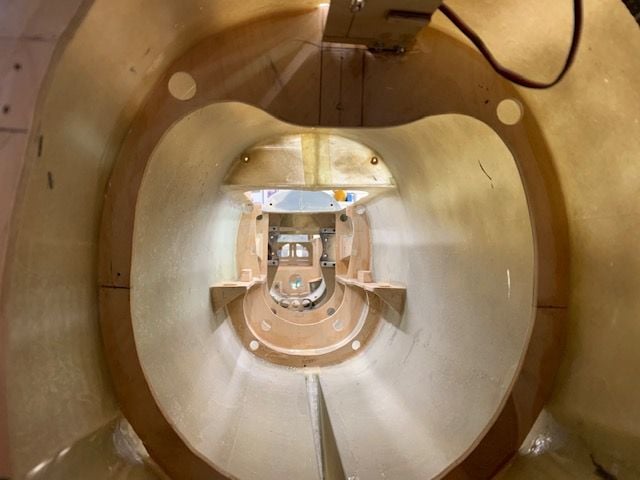
This photo from when planning turbine formers and holes were cut for servo wires and turbine wires in turbine formers
Fuel tank blocks lower path forward but there is plenty of room on top.
I had planned on laying out the fuel system components and plumbing this week but that required removing the turbine system from my Havoc to have the parts available to work with. Today, I decided not to take the turbine, ECU, and pump out of the Havoc until after the SC Tiger Meet in October so I could still fly it then. So, I started making the longest servo leads for the rudder and drag chute release. I'm using Powerbox Maxi wire for all flight controls and regular servo wire for the drag chute release. I immediately ran into a problem when routing the wires from the tail to the nose.
Two years ago when designing the formers I made holes for routing the servo and turbines wires along the bottom sides of the fuse in a traditional way just assuming it would be easy. Last spring when I made the fuel tank I made it too big and failed to leave room for the wiring beside the tank. The tank is now wide enough that it blocks the wire paths on both sides at the bottom of the fuse.
My plan now is to run the servo wires on the top sides of the fuse and over the wing openings. This is probably a better route anyway because the wires from the tail start at the top of the fuse and the new channels will be over the tank and out of the way of wing mounting screws. This will all be OK except there are no holes in the formers. So I will have to spend a day making new holes for wires and planning how to keep them away from the turbine and moving parts. Just another chapter...
This photo from when planning turbine formers and holes were cut for servo wires and turbine wires in turbine formers
Fuel tank blocks lower path forward but there is plenty of room on top.
Last edited by Viper1GJ; 09-28-2020 at 05:51 PM.
09-29-2020, 04:25 PM
#750
Thread Starter
My Feedback: (20)
Cutting holes for servo wires in top of fuse
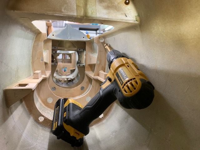
I was able to use the drill and 1/2" forstner bit for all holes except the front former. It was not easy to get drill and my hands inside to make the holes.
Holes in vertical fin former for rudder and drag chute release servos. The servo wires will go forward on the top edges of the fuse.
Holes in turbine formers and wing spar former.
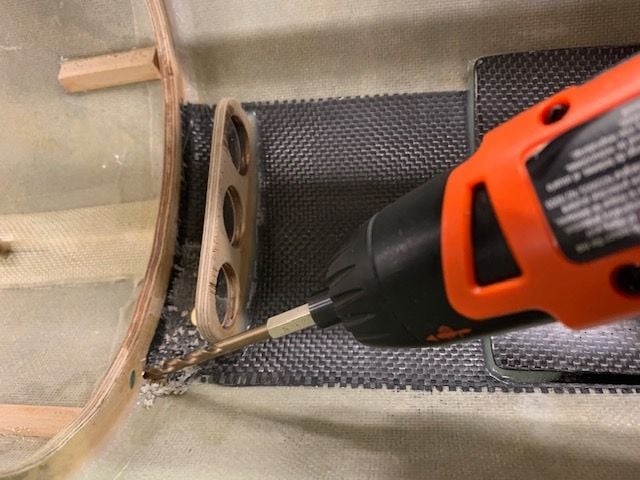
Corner gussets cut for tank front former
Grinder used to make the cuts in tank former and gussets glued in to hold wires and strengthen the former corners. Wires will drop to bottom to go under cockpit from here.
I was able to use the drill and 1/2" forstner bit for all holes except the front former. It was not easy to get drill and my hands inside to make the holes.
Holes in vertical fin former for rudder and drag chute release servos. The servo wires will go forward on the top edges of the fuse.
Holes in turbine formers and wing spar former.
Corner gussets cut for tank front former
Grinder used to make the cuts in tank former and gussets glued in to hold wires and strengthen the former corners. Wires will drop to bottom to go under cockpit from here.
Last edited by Viper1GJ; 09-29-2020 at 05:03 PM.