


1/6 F-105 Build Thread
 09-05-2020, 05:31 PM
#676

Thread Starter
My Feedback: (20)
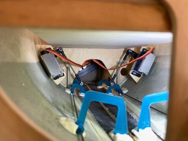
Beefed up stab servo mounts
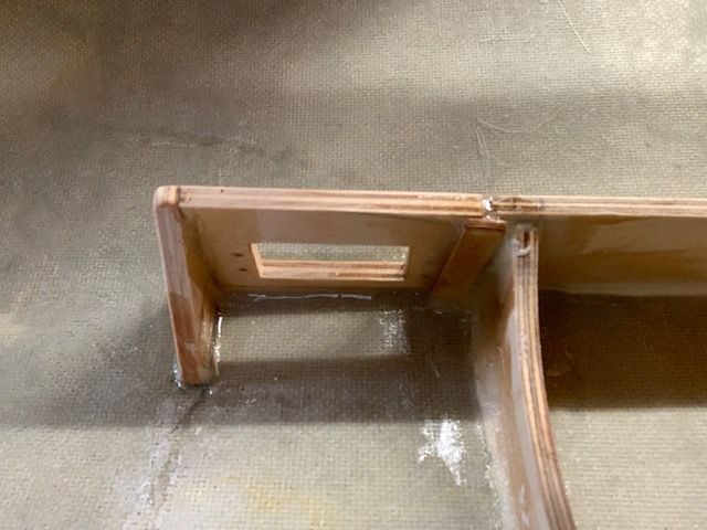
Reinforced stab servo mounts with a scab patch to engine mount plate and added a triangle bracket on the end

Same on the right

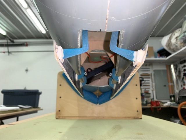
Applied epoxy fillet around all joint edges
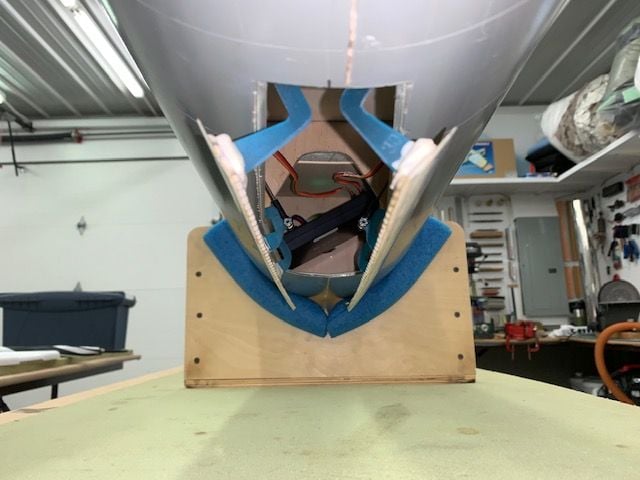
Same on right again

View from rear.
Reinforced stab servo mounts with a scab patch to engine mount plate and added a triangle bracket on the end
Same on the right
Applied epoxy fillet around all joint edges
Same on right again
View from rear.
 09-05-2020, 05:54 PM
#678
Thread Starter
My Feedback: (20)
Mounted air tanks.
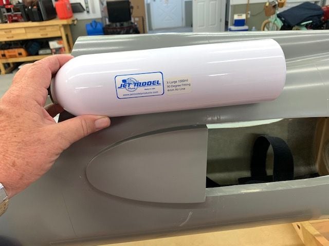
When I ordered the tanks from Ultimate Jets I was thinking that the "extra large" size was the same as I had used on several jets before thinking they were the big ones. However, when the tanks came I realized I had the "really big ones" (1000ml). I figured it would be ok since all the gear have 2 cylinders so the extra volume wound be good if they would fit. Today was the first time I tried fitting them in.

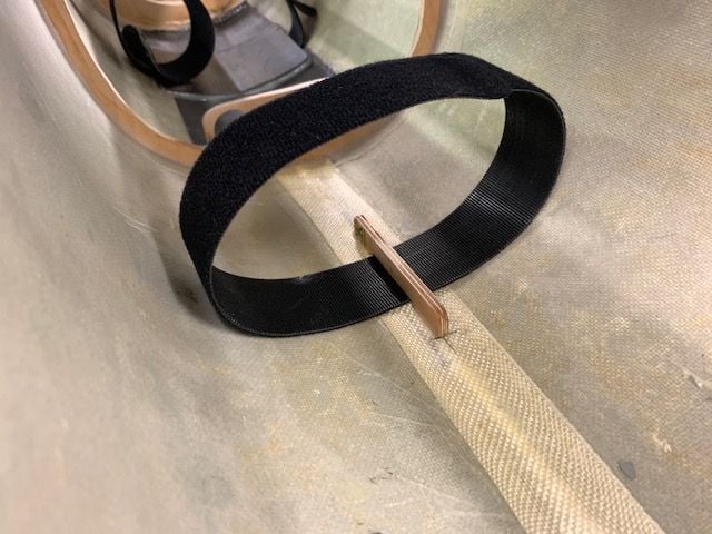
Spent about an hour looking at the placement and mounting method for air tanks and air trap. I want everything easily removable for accessibility and maintenance. I like using the Velcro one wrap straps for the air tanks. Gear tanks wound up on the floor behind the air trap.
The brake tank went on top in the turtle deck behind the canopy
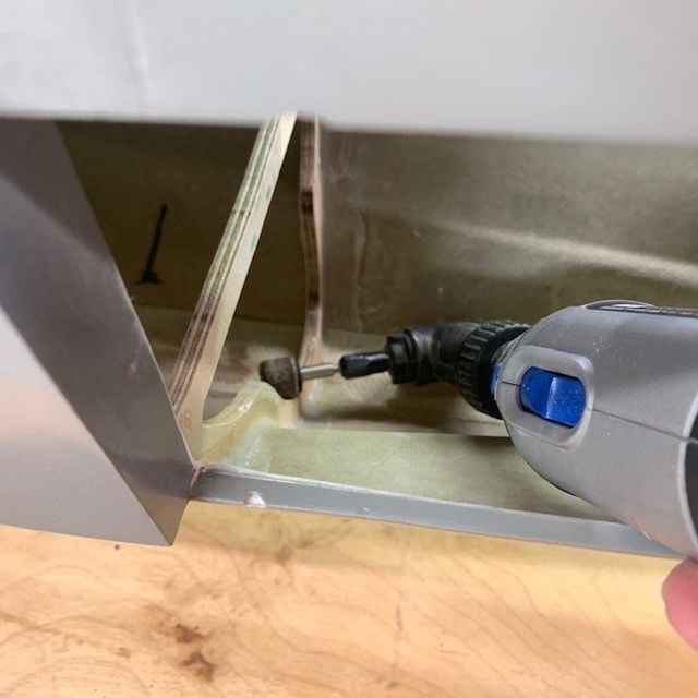
I flipped the fuse over and it took just a little shaving the former for the tank to fit in perfectly. Rather be lucky than good any day!
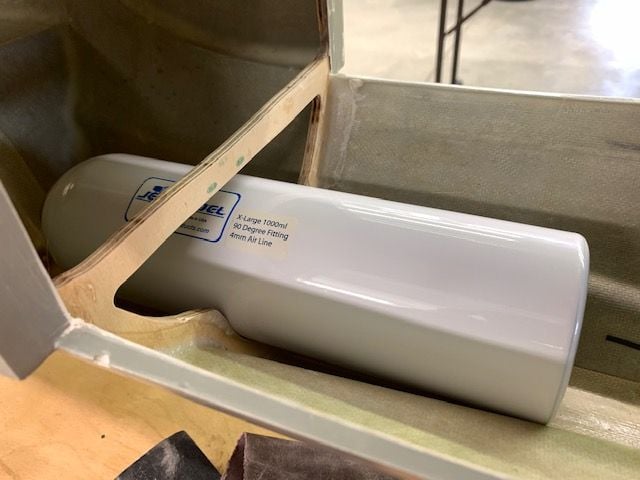
Looks like it was designed for the big tank!
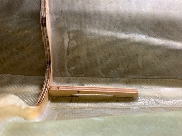
Small plywood bracket glued in for holding the Velcro strap

Bracket and strap ready

Done!
Same idea used for holding both the gear tanks to the floor

Done!
When I ordered the tanks from Ultimate Jets I was thinking that the "extra large" size was the same as I had used on several jets before thinking they were the big ones. However, when the tanks came I realized I had the "really big ones" (1000ml). I figured it would be ok since all the gear have 2 cylinders so the extra volume wound be good if they would fit. Today was the first time I tried fitting them in.
Spent about an hour looking at the placement and mounting method for air tanks and air trap. I want everything easily removable for accessibility and maintenance. I like using the Velcro one wrap straps for the air tanks. Gear tanks wound up on the floor behind the air trap.
The brake tank went on top in the turtle deck behind the canopy
I flipped the fuse over and it took just a little shaving the former for the tank to fit in perfectly. Rather be lucky than good any day!
Looks like it was designed for the big tank!
Small plywood bracket glued in for holding the Velcro strap
Bracket and strap ready
Done!
Same idea used for holding both the gear tanks to the floor
Done!
09-05-2020, 06:23 PM
#679
Thread Starter
My Feedback: (20)
Mounting air trap tank.
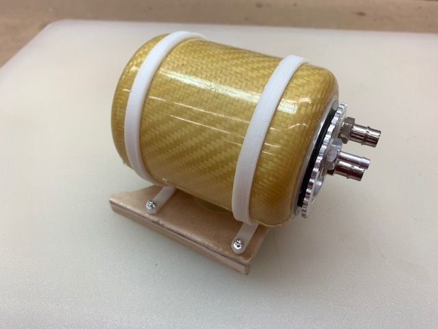
I got this air trap tank custom made by Ultimate Jets. I like the design because I can open it and clean or replace the pleated filter. It has 1/4" ID "Ultra High Flow" fittings for the K-320 and the 1/8" fitting for filling. I've been using 1/4" or 6mm ID plumbing from vent to pump since I started running the 300N+ turbines about 4 years ago. Probably overkill but I've never had any bubbles or high PWs so far.

Plywood mount fabricated.
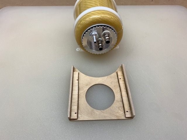
Bottom side
Screws installed
Dry fitting in fuse

Air trap mount epoxied to floor

Looks like fittings all smashed together...

However, fuel tubing is all above the air fittings and top of air trap tank is below the radio tray cut out in the former

View toward the rear.
I got this air trap tank custom made by Ultimate Jets. I like the design because I can open it and clean or replace the pleated filter. It has 1/4" ID "Ultra High Flow" fittings for the K-320 and the 1/8" fitting for filling. I've been using 1/4" or 6mm ID plumbing from vent to pump since I started running the 300N+ turbines about 4 years ago. Probably overkill but I've never had any bubbles or high PWs so far.
Plywood mount fabricated.
Bottom side
Screws installed
Dry fitting in fuse
Air trap mount epoxied to floor
Looks like fittings all smashed together...
However, fuel tubing is all above the air fittings and top of air trap tank is below the radio tray cut out in the former
View toward the rear.
09-05-2020, 06:59 PM
#680
Thread Starter
My Feedback: (20)
I saw Conway, SC but had no idea that was you. LIke I said still plugging along. No estimates on when, just when ever its done. Lots of stuff to make work still, the main gear retraction is the biggest. Plan on going Flying TIgers event next week. Maybe see you there.
Gary
09-05-2020, 07:48 PM
#681
My Feedback: (6)
Because I have a few risk factors, my doctor has forbidden me to attend the EOTY. Not happy about it, but I know i got plenty frustrated when my patients failed to heed my advice, so I will stay home. Nevertheless, i am holding out hope to attend the October jet event. Hoping, like most folks, that COVID will be disappearing in the rear view mirror by then!
I am not working on any projects unless you count honey do's! I have the new Freewing Mig 29 inbound. ETA in mid September so perhaps have my grimy hands on it by early October!
Take good care
James
PS- Frank remains consumed by his house buiding project. I doubt he will be back before maybe january, if then, Pity really
09-06-2020, 04:48 PM
#683
My Feedback: (6)
Roger that! I am getting antsy ready to fly and ready to have David preflight the new Ultrabandit EVO and maiden it
Hopefull folks will posr copious photos rfom EOTY this cpoming weekend.
I truly and enjoying watching the machinations of an engineer's logical mind solving all these issues in a step wise fashion! I am learning so please continue posting
James
Hopefull folks will posr copious photos rfom EOTY this cpoming weekend.
I truly and enjoying watching the machinations of an engineer's logical mind solving all these issues in a step wise fashion! I am learning so please continue posting
James
09-06-2020, 05:39 PM
#685
Thread Starter
My Feedback: (20)
Removing CB 400 from Havoc
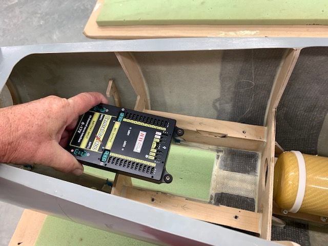
Now with the primary flight controls working, I need to start building an F-105 model file in the in the Jeti DS-24 to make all the other functions start working like gear, gear doors, drag chute, etc... So it was time to get the CB 400 I got last summer for the F-105 out of the Havoc. I used it for a year in the Havoc and now it's time to move it over to the Thud. I'll replace it in the Havoc with a CB 200 I have from my old Avanti which was sold earlier this year.

Havoc rolled in shop for transplant surgery.
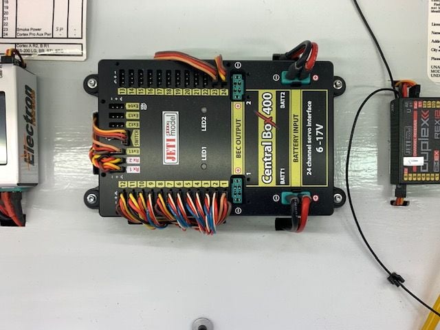
CB 400 in Havoc prior to removal

First step is to label all the leads with my shrink wrap label maker I got for Christmas last year. Wished I had this thing years ago.
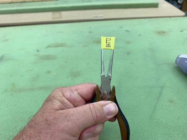
I had to stretch the 1/2" shrink tube with pliers to fit over the large multiplex battery leads.
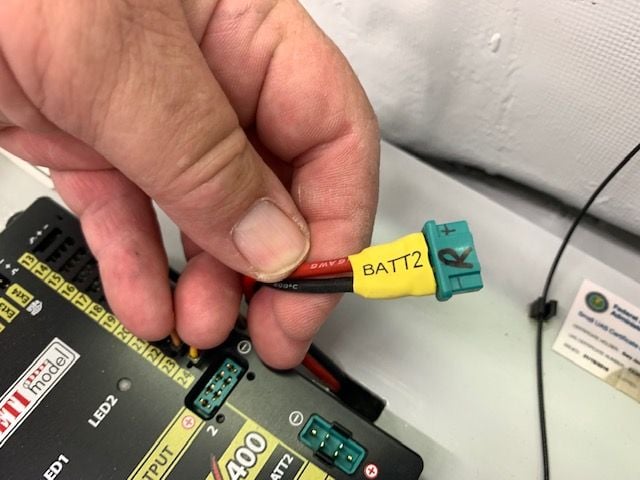
After a big stretch it shrank right down on the wires with no problem.

The rest of the labels slipped on easily and shrank down snug on the servo wires. I used this small nozzle embossing heat gun from Hobby Lobby to keep from blasting the whole area with hot air. The whole process took just a few minutes.
CB 400 looking for a new home!
Now with the primary flight controls working, I need to start building an F-105 model file in the in the Jeti DS-24 to make all the other functions start working like gear, gear doors, drag chute, etc... So it was time to get the CB 400 I got last summer for the F-105 out of the Havoc. I used it for a year in the Havoc and now it's time to move it over to the Thud. I'll replace it in the Havoc with a CB 200 I have from my old Avanti which was sold earlier this year.
Havoc rolled in shop for transplant surgery.
CB 400 in Havoc prior to removal
First step is to label all the leads with my shrink wrap label maker I got for Christmas last year. Wished I had this thing years ago.
I had to stretch the 1/2" shrink tube with pliers to fit over the large multiplex battery leads.
After a big stretch it shrank right down on the wires with no problem.
The rest of the labels slipped on easily and shrank down snug on the servo wires. I used this small nozzle embossing heat gun from Hobby Lobby to keep from blasting the whole area with hot air. The whole process took just a few minutes.
CB 400 looking for a new home!
Last edited by Viper1GJ; 09-06-2020 at 05:44 PM.
09-07-2020, 04:45 PM
#686
Thread Starter
My Feedback: (20)
Installing forward equipment tray
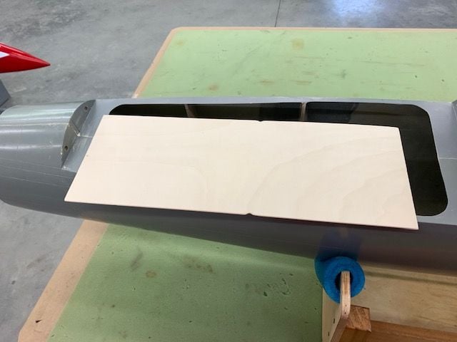
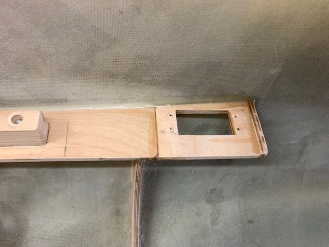
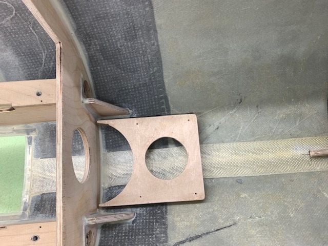
Forward equipment tray cut from 1/8" light ply. Notches allow fit over the F2 former which for some reason I had cut a slightly smaller opening than the F3 former. Plan is to hold tray in place with just 2 screws in the rear to make it easy to remove or lift up to get to the bottom side.
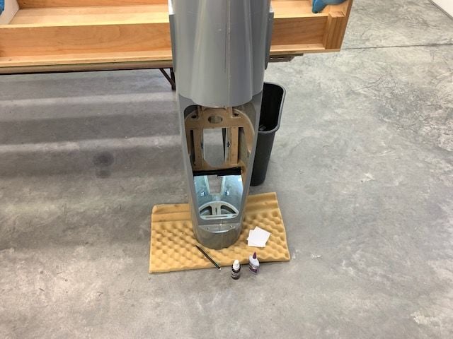
Stood fuse on nose to glue front tray holding brackets in place.

Light ply spacers taped between the wood strips to set the proper spacing between the two strips.

Front tray holding strips in place
Tray engaged in front slot with screws to hold the rear edge down
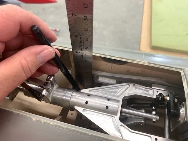
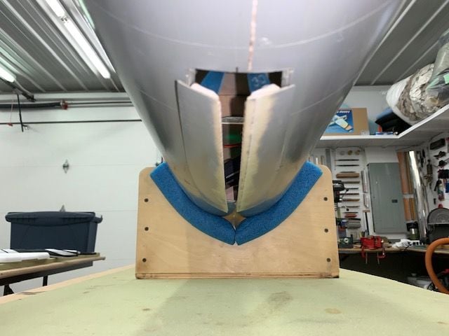
Next was to mark the relief hole for the nose gear cylinders that stick up through the tray. Tray taped in place and fuse turned upside down to mark the lines to cut

Locating the rear cut line by projecting the slope of the cylinders to the ruler

Filling in the lines to cut

Cut out complete. This hole will have a cover but here is where I found the cover could interfere with the air lines from both cylinders.
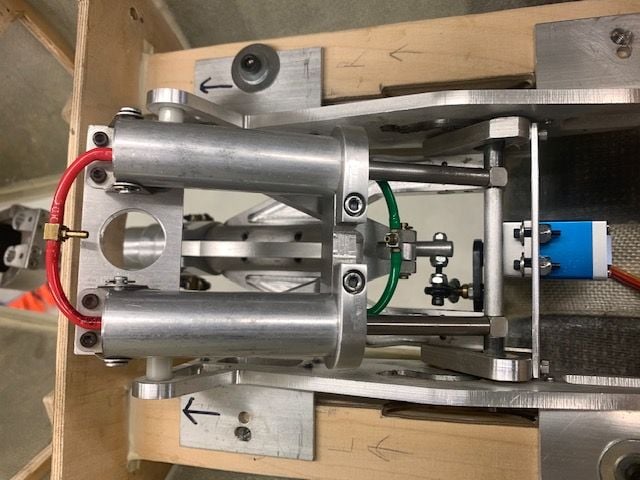
Next was to add air lines to see how much clearance was needed to clear the tray and cover for the cut out. I also injected some silicone oil in the cylinders since who knows how many years they have been sitting around. Getting the lines on and the nipple at the best angle took a while. My color code is green for down and red for up since every real jet I flew had green for down and red for up or unlocked.
It turned out to be not as bad as I thought since I figured out a way to have all the air lines go under the tray
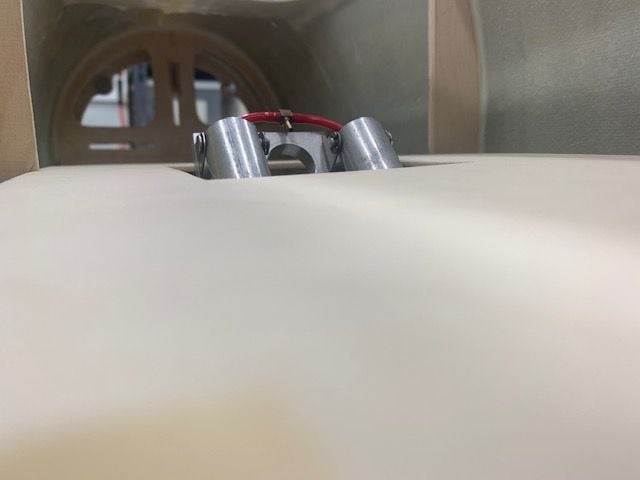
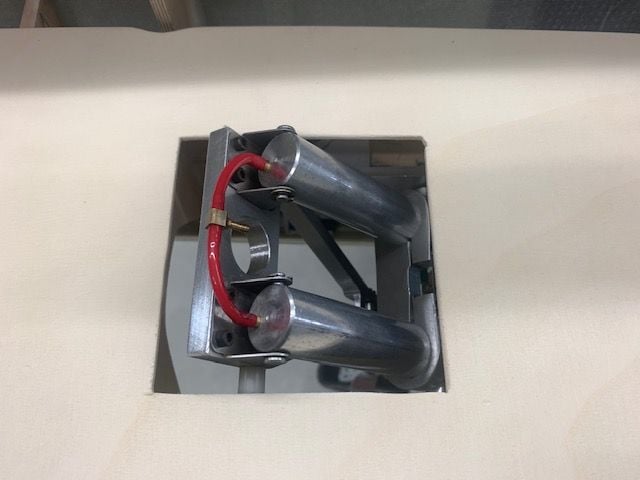
Cylinders stick up about 3/4" above the tray. They will be covered by a lite ply bump up and cylinders will be hidden from above.
Next I discovered the servo arms for the nose gear doors would contact the bottom of the tray in the door closed position. This required shortening the push rods and adjusting the servo end points. I got close here but ran out of time. Still need to shorten the push rods a little more to keep the servo arms from bumping into the tray when doors are closed.
Forward equipment tray cut from 1/8" light ply. Notches allow fit over the F2 former which for some reason I had cut a slightly smaller opening than the F3 former. Plan is to hold tray in place with just 2 screws in the rear to make it easy to remove or lift up to get to the bottom side.
Stood fuse on nose to glue front tray holding brackets in place.
Light ply spacers taped between the wood strips to set the proper spacing between the two strips.
Front tray holding strips in place
Tray engaged in front slot with screws to hold the rear edge down
Next was to mark the relief hole for the nose gear cylinders that stick up through the tray. Tray taped in place and fuse turned upside down to mark the lines to cut
Locating the rear cut line by projecting the slope of the cylinders to the ruler
Filling in the lines to cut
Cut out complete. This hole will have a cover but here is where I found the cover could interfere with the air lines from both cylinders.
Next was to add air lines to see how much clearance was needed to clear the tray and cover for the cut out. I also injected some silicone oil in the cylinders since who knows how many years they have been sitting around. Getting the lines on and the nipple at the best angle took a while. My color code is green for down and red for up since every real jet I flew had green for down and red for up or unlocked.
It turned out to be not as bad as I thought since I figured out a way to have all the air lines go under the tray
Cylinders stick up about 3/4" above the tray. They will be covered by a lite ply bump up and cylinders will be hidden from above.
Next I discovered the servo arms for the nose gear doors would contact the bottom of the tray in the door closed position. This required shortening the push rods and adjusting the servo end points. I got close here but ran out of time. Still need to shorten the push rods a little more to keep the servo arms from bumping into the tray when doors are closed.

 09-08-2020, 04:09 PM
#689
Thread Starter
My Feedback: (20)
That's my plan. All the lines from the tanks through the valves to the gear will be 4mm. I have 4mm to 3mm Festo reducers that will go in just prior to the T and into each cylinder. I wanted to replace the cylinder nipples with bigger ones but there is no room on the end of the cylinders where the shaft comes out for a bigger nipple. Hopefully the hi flow lines and valves up to the T will help some but it still gets reduced at the T. It would be good if there was a reducing T with a 4mm inlet somewhere but I don't know if there are any such things available or where to look.
Thanks,
Gary
Last edited by Viper1GJ; 09-08-2020 at 04:12 PM.
09-08-2020, 07:56 PM
#690
 09-08-2020, 08:40 PM
#691
Hi Thomas,
That's my plan. All the lines from the tanks through the valves to the gear will be 4mm. I have 4mm to 3mm Festo reducers that will go in just prior to the T and into each cylinder. I wanted to replace the cylinder nipples with bigger ones but there is no room on the end of the cylinders where the shaft comes out for a bigger nipple. Hopefully the hi flow lines and valves up to the T will help some but it still gets reduced at the T. It would be good if there was a reducing T with a 4mm inlet somewhere but I don't know if there are any such things available or where to look.
Thanks,
Gary
clippard has all sorts of Tee�s and such. I was just looking a few days ago and they have 1/16� tee�s with a 3/32 or 1/8� inlet barb
09-09-2020, 04:52 PM
#692
Thread Starter
My Feedback: (20)
Auburn02 I looked at the larger push to connect Y but I was trying to find the smaller barbed fittings to reduce the size.
Thomas, I will look there for the smaller connectors. Thanks.
Gary
Thomas, I will look there for the smaller connectors. Thanks.
Gary
09-09-2020, 05:14 PM
#693
How much smaller? That Y reduces from a single 4mm inlet line to twin 3mm outlet lines which would allow you to feed a 4mm line from the valve to the Y, then 2x 3mm lines (i.e. the red lines in your recent pics) to your cylinders. Or I might be completely misunderstanding what you're wanting to do.
BTW I like your color scheme for the gear lines, I always try to do the same.
BTW I like your color scheme for the gear lines, I always try to do the same.
09-09-2020, 05:30 PM
#694
Thread Starter
My Feedback: (20)
I was thinking more about the main gears just trying to keep the connector away from the retracts as things are moving and there is not much room close in. It may actually work to move the Y connector away and just feed the two smaller lines from a little farther away. I like the push to connect connectors because they are easy work with and there is always the maintenance later on where they make it easy to get stuff out. I have several 4 to 3mm PTC reducers now but did not get any Ys yet. I also just found some reducing Ts on Clippard. I look at what may work best next week. Packing up tomorrow to go to a local fly in this weekend. Thanks again for the suggestions. It helps me see things other than how I had first thought about.
 09-10-2020, 11:51 AM
#696
Six10 vs Hysol
I first used Six10 about 5 years ago on my Sabre XLT project and thought it was pretty good. For the past several years I was using Hysol 9462 for thickened epoxy uses just because it seemed everybody else used it.
Last week I found I was almost out of Hysol and needed to do some "house keeping" gluing to lots of items I had just tack glued for fitting, including the vertical fin former recently installed. I recently got a box of 100 10ml syringes for about $14 on Amazon. I planned on using them for mixing my own thickened epoxy after watching Paul A's videos converting the foamy T-33.
I decided to use the Six10 again with the syringes and found it to be really good and much easier use than before with out the syringes. And then I figured the price per ml again and I'm really sold this time. Hysol is $16-$20 per 50ml tube. Six10 is $25-$28 per 190ml tube depending on where I can get it. I figure it's about half price and seems to do just as well. I can stuff the syringe for that.
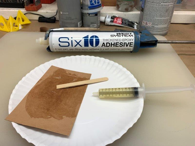
Six10 mixed on cardboard pad and stuffed into the syringe by removing the plunger and scraping the open syringe tube over the epoxy till its all in. Wipe off the base of the syringe and insert plunger.
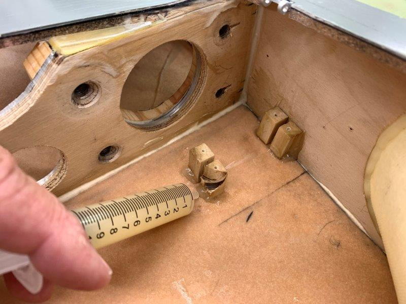
Applying glue fillet around base of gear door servo mounts
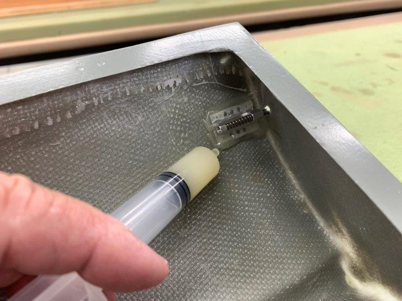
Same on canopy latches and dowels. It did an great job on the fuse former and drag chute door hinges also. Don't have and technical data on it but it seems as good or better than Hysol 9462 at less cost.
I first used Six10 about 5 years ago on my Sabre XLT project and thought it was pretty good. For the past several years I was using Hysol 9462 for thickened epoxy uses just because it seemed everybody else used it.
Last week I found I was almost out of Hysol and needed to do some "house keeping" gluing to lots of items I had just tack glued for fitting, including the vertical fin former recently installed. I recently got a box of 100 10ml syringes for about $14 on Amazon. I planned on using them for mixing my own thickened epoxy after watching Paul A's videos converting the foamy T-33.
I decided to use the Six10 again with the syringes and found it to be really good and much easier use than before with out the syringes. And then I figured the price per ml again and I'm really sold this time. Hysol is $16-$20 per 50ml tube. Six10 is $25-$28 per 190ml tube depending on where I can get it. I figure it's about half price and seems to do just as well. I can stuff the syringe for that.
Six10 mixed on cardboard pad and stuffed into the syringe by removing the plunger and scraping the open syringe tube over the epoxy till its all in. Wipe off the base of the syringe and insert plunger.
Applying glue fillet around base of gear door servo mounts
Same on canopy latches and dowels. It did an great job on the fuse former and drag chute door hinges also. Don't have and technical data on it but it seems as good or better than Hysol 9462 at less cost.
Wait, how did I miss this gem??!!!
Viper, is this six10 thixotropic? Does it stay where you put it?
09-10-2020, 12:27 PM
#697

I do the above with both Hysol and thickened epoxy, using 3mL syringes for small to medium tasks. I cut off the luer lock outer thread of the syringe to expose the inner nozzle. You can also use some 4mm fuel tube over the nozzle to extend it to get to hard to reach areas.
Paul
Paul
09-10-2020, 05:52 PM
#699
Thread Starter
My Feedback: (20)
Nose gear doors adjusted
Shortened nose door pushrods to get closed position with out bumping into the tray above servo arms
Full open
Closing...
Almost closed...

Closed
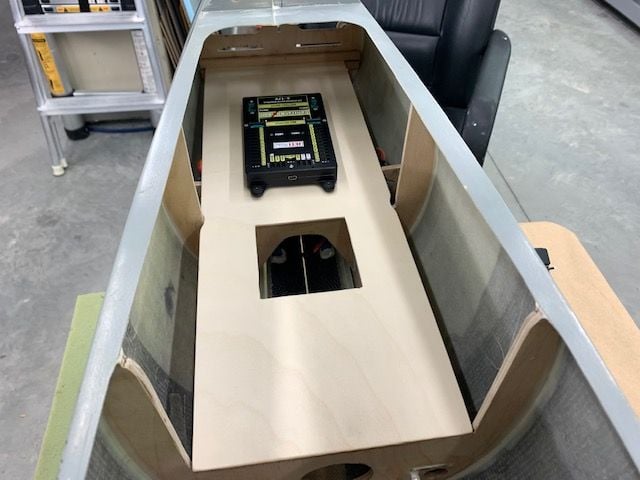
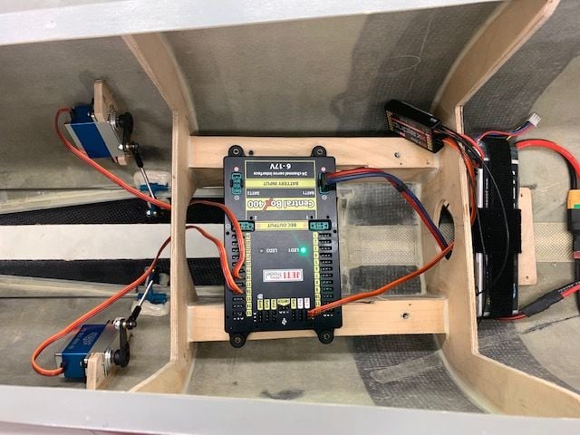
Planned location of CB 400 on tray.
Shortened nose door pushrods to get closed position with out bumping into the tray above servo arms
Full open
Closing...
Almost closed...
Closed
Planned location of CB 400 on tray.
09-10-2020, 05:57 PM
#700
Thread Starter
My Feedback: (20)
Gary