


1/6 F-105 Build Thread
 08-26-2020, 05:20 PM
#651

Thread Starter
My Feedback: (20)
I thought about that but that would make the other one too short. The right side is about 4mm short but that could be adjusted by the ball joint adjustment. I'll probably just cut both of them, get them both the right length again and then cover the cut with the 10mm CF tubing. The 10mm tube would butt up to the aluminum cap which is also 10mm in diameter so it would look ok at the cap. I would run the outer 10mm CF tube back about 6 inches on both sides and it would look the same plus it would give plenty of surface area to glue the tubes together and I could re pin them on either side of the cut. Thanks for the suggestion.
 08-26-2020, 11:21 PM
#652
Viper if you can get the cross pins out I have successfully removed these rod ends by heating them up with a heat gun, it softens the epoxy up ,the first end will usually pop off as the air inside expands.
 08-27-2020, 06:08 AM
#653
My Feedback: (3)
Push rod too long!
Well I screwed the pooch on this one. Don't know what, how, when, or where I screwed up but one push rod is 10mm too long. I don't know if the sub trim was off, the arm was on wrong spline, or blah, blah, blah, blah. There is no amount of programming endpoints, sub trim, clevis adjustment etc that will fix this and keep symetrical movement on both stabs. My only choice is to fix it. The only problem is it all glued in and pinned inside the aluminum cap, and will not come out easily. I'm thinking about cutting the 8mm CF tube, splicing inside with a 6mm tube, and sliding a 10mm carbon tube over the splice and gluing everything back together. It will be fine except it will look like a 3rd grader made it. Arrrgh!
I'll have to wait till next week. Grandkids flew in from Texas for the week so I will stew on it for a few days. Arrgh!
08-27-2020, 05:44 PM
#655
Thread Starter
My Feedback: (20)
Thanks for the heating ideas. I was just trying to fix it with the supplies I have on hand. I don't have any more rod ends here and I don't want to mess up the rod ends trying to get the pin out. It would probably mess up the CF tubes by heating and I don't have any more of those here with out reordering.. The pins were CA glued in before peening the end flat so they're really in there. Maybe soaking in acetone would free them after the pin end was ground off. I think the cut and splice method would be easier to get the correct length accurate rather than removing the rod ends. At least I have some 10mm CF tube here that I could slide over the splice and epoxy it all together. Still pondering the best fix with out getting all new parts. I think my end joints are good so I could still use them on both push rods also. Still a few days before I get any more shop time so suggestions welcome.
Thanks again.
Gary
Thanks again.
Gary


 08-28-2020, 12:49 PM
#660
My Feedback: (1)
Understood, but as long as the servo arms and the stabilizer arms are the same, and the angles of both on both sides are the same a slight difference in the actual pushrod length makes absolutely no difference. I'd leave it alone, to much work to fix what is a non-issue really, my opinion of course.

 08-29-2020, 03:42 PM
#664
Thread Starter
My Feedback: (20)
Gary
Last edited by Viper1GJ; 08-29-2020 at 06:23 PM.
08-30-2020, 05:53 AM
#665

That's exactly it since one pushrod is longer than the other. If my fix is not satisfactory, I will just order new stuff and start over. I'm still a few days from shop time again. I will post photos of the fix when I get back to it and see which way to go then. Thanks to all for suggestions.
Gary
Gary
just incase it hasnt been suggested, just flip the servo around. LOL
08-30-2020, 04:00 PM
#666
Thread Starter
My Feedback: (20)
Gary
The following users liked this post:
invertmast (08-30-2020)

The following users liked this post:
invertmast (08-30-2020)
09-02-2020, 04:48 PM
#668
Thread Starter
My Feedback: (20)
Pushrod corrections
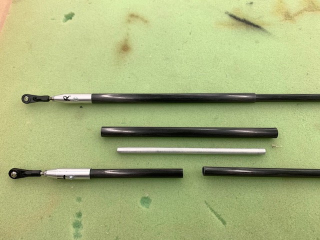
Well after being away for a week with a house full of small grandkids I finally got back to the shop today for an hour with a "I don't care" attitude and decided to chop up the pushrods and make them correct size. If this does not come out satisfactory then I will just reorder stuff and start over.

I laid out the parts from the scrap box I have and measured for cutting. The left rod is too long so I planned to cut out a section and shorten it. The right rod is just slightly short so I will lengthen it a little. The aluminum tube fits snugly inside the 6mm CF tube with no slop. The plan is to insert a piece of aluminum tubing inside the 6mm CF tube for a splice and epoxy in at the correct length. Then I will slide a piece of 8mm CF tube over the joint and epoxy that in place. The push rod compression and tension load will be carried over the splice by the 8mm CF tube.

Parts cut and test fitted, These gaps are extra wide just for the photo. When in proper place there is almost no gap between the 6mm CF rod pieces.
Here the right push rod (top) is dry fit in final form. The left push rod (bottom) shows the separate parts ready for assembly. Next I will install the pushrods with the stabs taped on the fuse fillets and turn on the servos. I will recheck all the servo arm spline settings, subtrims, and endpoint adjustments to make sure the push rods are epoxied together with everything centered.
I stopped here tonight and will epoxy everything together tomorrow after I get some rest. After a full fay of catch up house chores and two appointments (dentist and eye doc) I didn't want to screw it up again from being tired.
Well after being away for a week with a house full of small grandkids I finally got back to the shop today for an hour with a "I don't care" attitude and decided to chop up the pushrods and make them correct size. If this does not come out satisfactory then I will just reorder stuff and start over.
I laid out the parts from the scrap box I have and measured for cutting. The left rod is too long so I planned to cut out a section and shorten it. The right rod is just slightly short so I will lengthen it a little. The aluminum tube fits snugly inside the 6mm CF tube with no slop. The plan is to insert a piece of aluminum tubing inside the 6mm CF tube for a splice and epoxy in at the correct length. Then I will slide a piece of 8mm CF tube over the joint and epoxy that in place. The push rod compression and tension load will be carried over the splice by the 8mm CF tube.
Parts cut and test fitted, These gaps are extra wide just for the photo. When in proper place there is almost no gap between the 6mm CF rod pieces.
Here the right push rod (top) is dry fit in final form. The left push rod (bottom) shows the separate parts ready for assembly. Next I will install the pushrods with the stabs taped on the fuse fillets and turn on the servos. I will recheck all the servo arm spline settings, subtrims, and endpoint adjustments to make sure the push rods are epoxied together with everything centered.
I stopped here tonight and will epoxy everything together tomorrow after I get some rest. After a full fay of catch up house chores and two appointments (dentist and eye doc) I didn't want to screw it up again from being tired.
Last edited by Viper1GJ; 09-02-2020 at 04:56 PM.
09-03-2020, 05:12 PM
#669
Thread Starter
My Feedback: (20)
Splicing pushrods

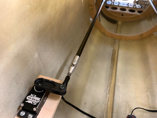
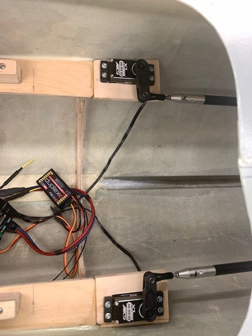
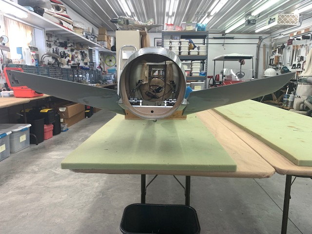
Stabs are taped in position to fuse

The servos were turned on and checked for arm spline attachment, subtrim, 100% travel, and endpoints. After making sure the servos were symmetrical, epoxy was applied to the aluminum splice tube and then it was inserted inside the 6mm CF pushrod. Then the pushrod was installed on the stab horn and servo arm and adjusted to proper length and bolt inserted in servo arm.
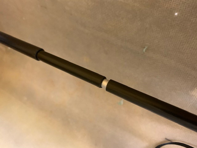
This is the gap on the left side, about 4mm, after adjusting the splice to proper length.
Excess epoxy cleaned off inner 6mm rod and the 8mm sleeve was slid over the splice to keep it straight during cure.
Left side done the same way
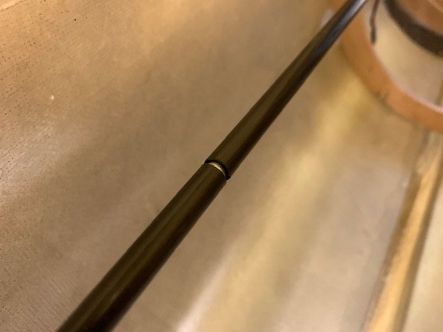
About a 2mm gap on the right side.

Servo battery disconnected and splice joints allowed to cure.
Stabs are taped in position to fuse
The servos were turned on and checked for arm spline attachment, subtrim, 100% travel, and endpoints. After making sure the servos were symmetrical, epoxy was applied to the aluminum splice tube and then it was inserted inside the 6mm CF pushrod. Then the pushrod was installed on the stab horn and servo arm and adjusted to proper length and bolt inserted in servo arm.
This is the gap on the left side, about 4mm, after adjusting the splice to proper length.
Excess epoxy cleaned off inner 6mm rod and the 8mm sleeve was slid over the splice to keep it straight during cure.
Left side done the same way
About a 2mm gap on the right side.
Servo battery disconnected and splice joints allowed to cure.
09-03-2020, 05:25 PM
#670
Thread Starter
My Feedback: (20)
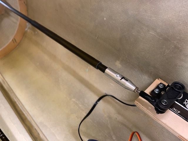
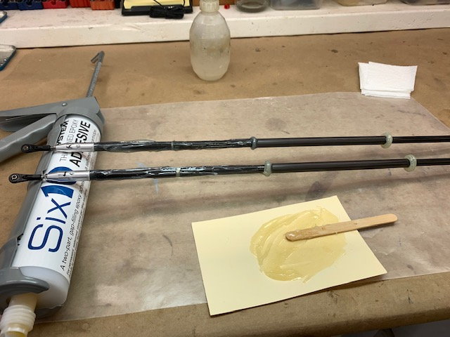
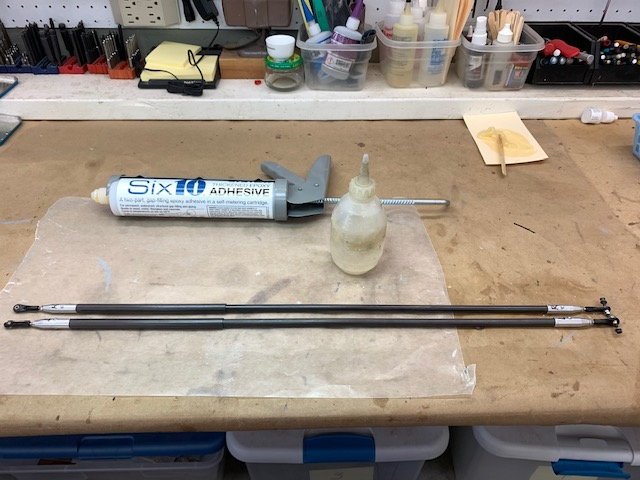
Installing CF sleeves over the pushrod splices

Pushrod splice joints cured and 8mm sleeves ready to install
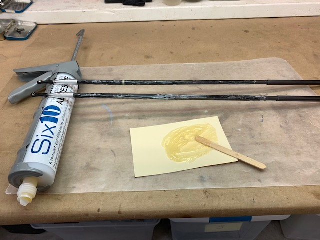
Epoxy mixed and applied to pushrods
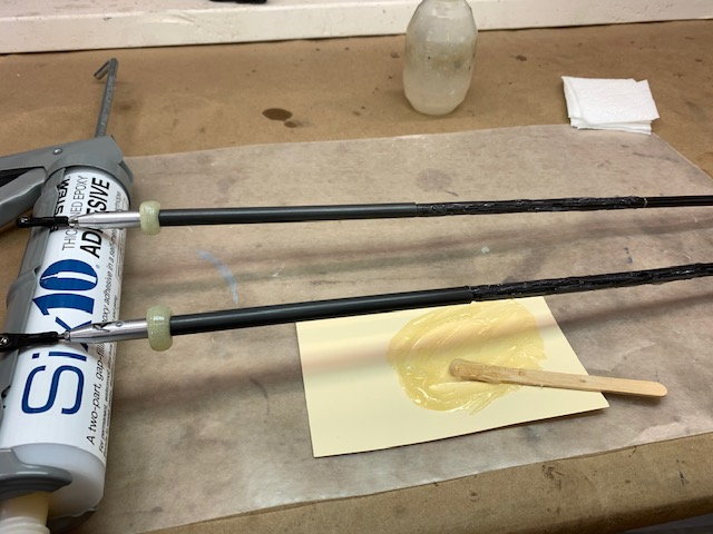
8mm sleeves rotated and pushed against the aluminum rod cap.
Epoxy reapplied behind sleeves and sleeves pushed back on push rod to ensure epoxy completely covers the inside of the sleeves
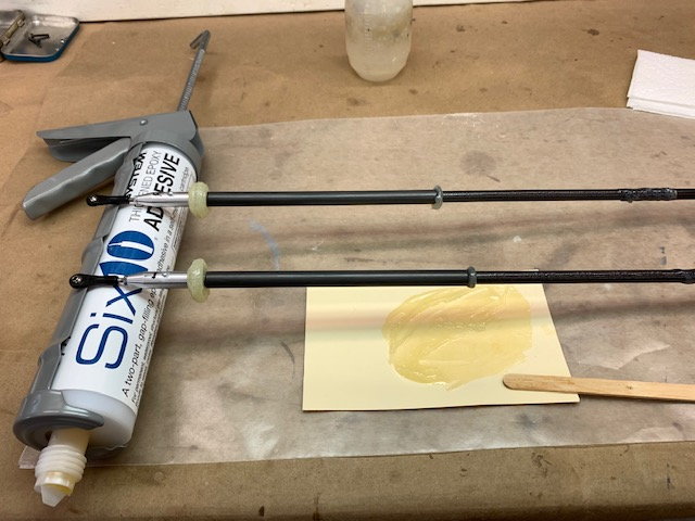
Sleeves pushed back up against the rod caps to final placement and excess epoxy squeeze out removed.

Excess epoxy cleaned off push rods with alcohol.
All done and set aside for cure. I think these push rods will work OK. I'll give them the pull test after cure.
Pushrod splice joints cured and 8mm sleeves ready to install
Epoxy mixed and applied to pushrods
8mm sleeves rotated and pushed against the aluminum rod cap.
Epoxy reapplied behind sleeves and sleeves pushed back on push rod to ensure epoxy completely covers the inside of the sleeves
Sleeves pushed back up against the rod caps to final placement and excess epoxy squeeze out removed.
Excess epoxy cleaned off push rods with alcohol.
All done and set aside for cure. I think these push rods will work OK. I'll give them the pull test after cure.
Last edited by Viper1GJ; 09-03-2020 at 05:30 PM.
09-04-2020, 05:32 PM
#673
Thread Starter
My Feedback: (20)
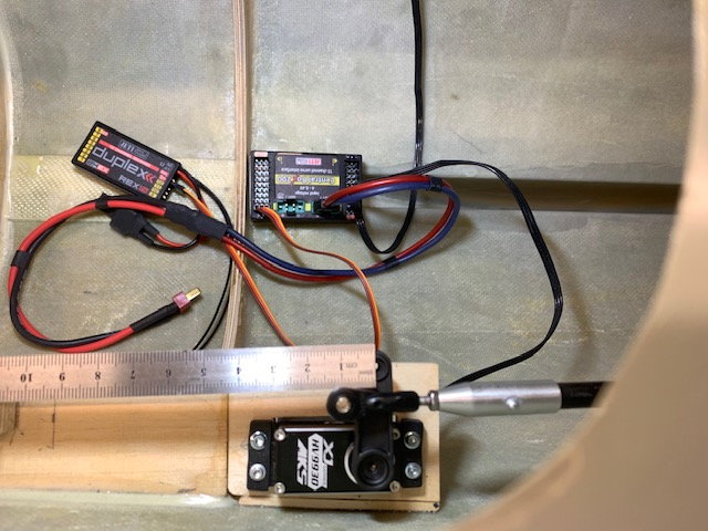
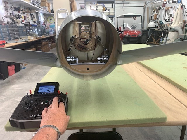
Programming stab servos
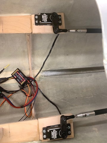
Got push rods installed and servos synced up. Endpoints programmed and offset curve used because the full down travel available is less than full up.
Full down

Full up
Full up
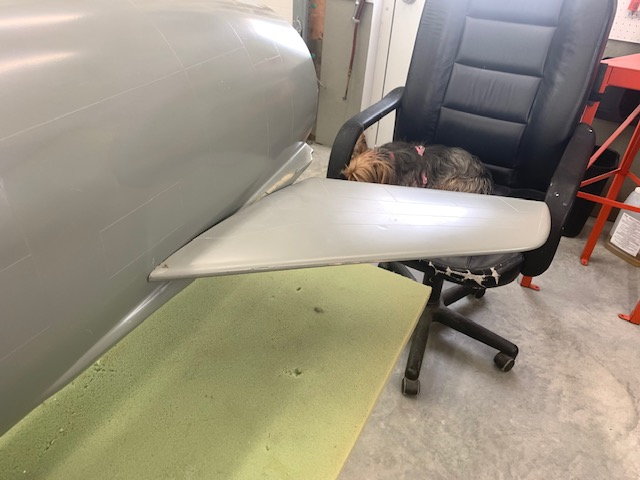
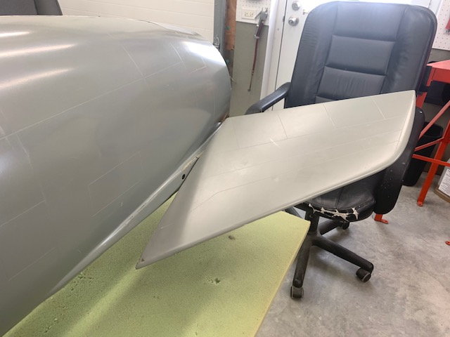
Full down. Down travel is limited because the leading edge of the stab root touches the fuse side and stops the down travel. Don't think it is a big deal on this type of jet. Servo end points reduced to keep the stab from touching the fuse. My supervisor is resting in the chair.

Full down
Full up

Down
Up. Feels good to finally have all the flight controls going and programmed.
Got push rods installed and servos synced up. Endpoints programmed and offset curve used because the full down travel available is less than full up.
Full down
Full up
Full up
Full down. Down travel is limited because the leading edge of the stab root touches the fuse side and stops the down travel. Don't think it is a big deal on this type of jet. Servo end points reduced to keep the stab from touching the fuse. My supervisor is resting in the chair.
Full down
Full up
Down
Up. Feels good to finally have all the flight controls going and programmed.