


1/6 F-105 Build Thread
 08-13-2020, 04:57 PM
#626

Thread Starter
My Feedback: (20)
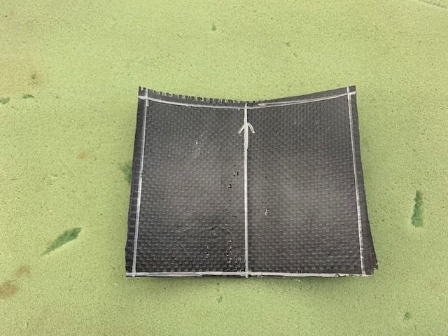
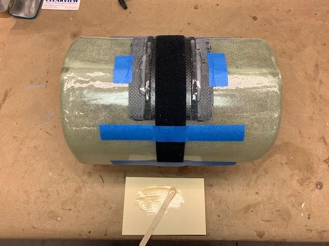
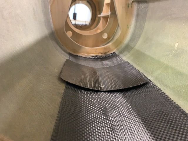
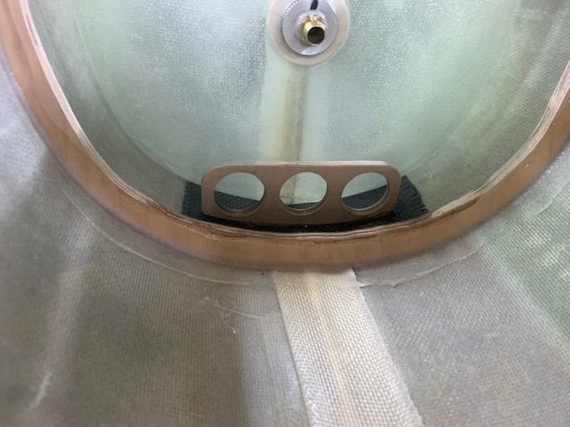
Carbon fiber tank mount
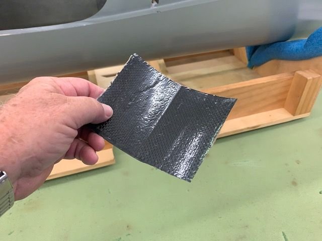
The first tank mount attempt failed in 2 ways. First it was only 3 layers and came out not stiff enough and was easy to twist. 2nd the epoxy bonded the thin plastic to the CF. I could not even scrape it off. This one went to the trash.
2nd attempt used thicker plastic and some release wax. It peeled off easy. I also used 6 layers alternating on the 45 degree bias angle.
This one came out stiff and strong.
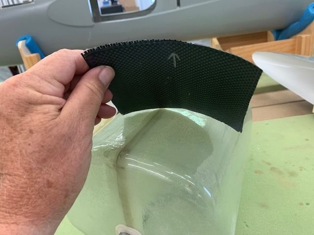
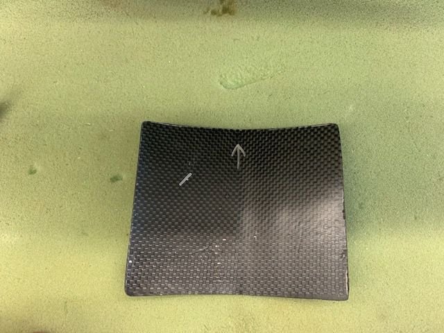
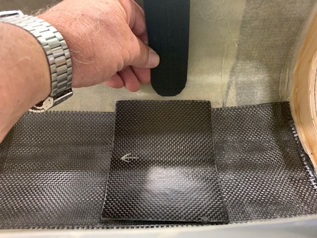
Dry fit to bottom of tank with Velcro One Wrap strap
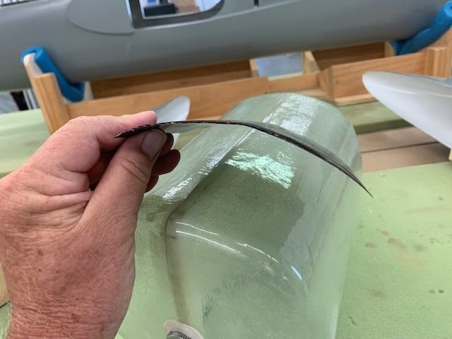
Marked for trimming
Edges trimmed and sanded smooth
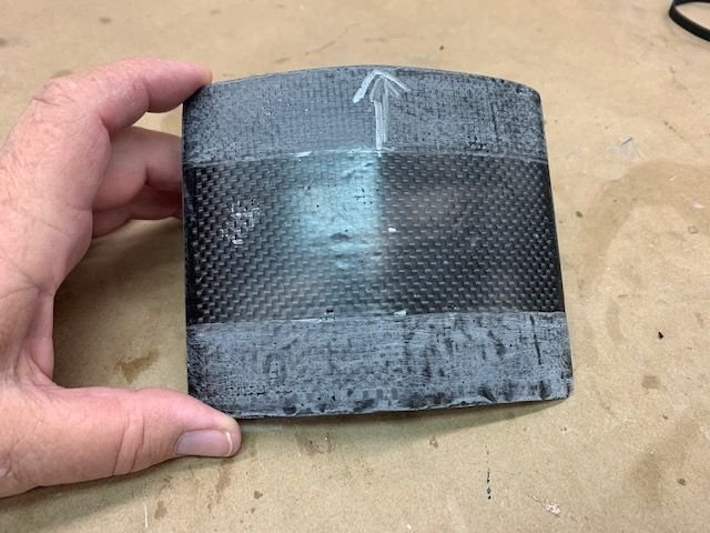
Srap is 1.5 inches wide. Center section is left smooth in center 2 inches. Front and aft edges scuffed up for epoxy bonding to fuse floor.
The first tank mount attempt failed in 2 ways. First it was only 3 layers and came out not stiff enough and was easy to twist. 2nd the epoxy bonded the thin plastic to the CF. I could not even scrape it off. This one went to the trash.
2nd attempt used thicker plastic and some release wax. It peeled off easy. I also used 6 layers alternating on the 45 degree bias angle.
This one came out stiff and strong.
Dry fit to bottom of tank with Velcro One Wrap strap
Marked for trimming
Edges trimmed and sanded smooth
Srap is 1.5 inches wide. Center section is left smooth in center 2 inches. Front and aft edges scuffed up for epoxy bonding to fuse floor.
 08-13-2020, 05:18 PM
#627
Thread Starter
My Feedback: (20)
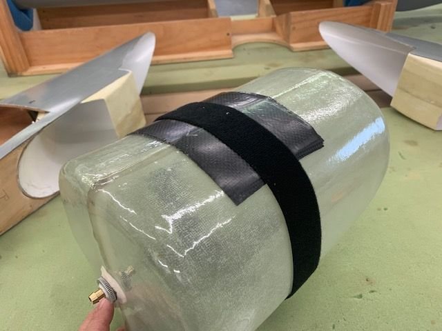
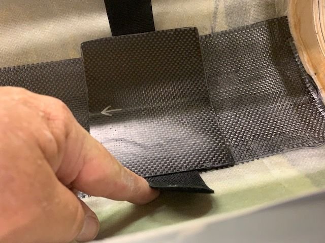
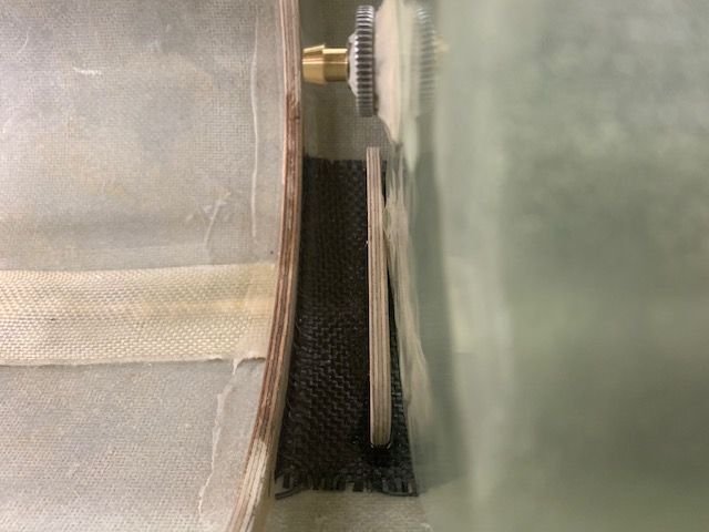
Installing tank mount plate
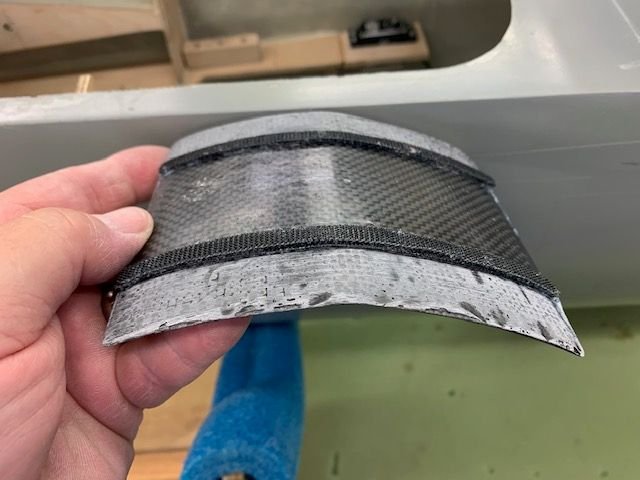
Two layers of velcro strips were glued to the bottom of the plate with thin CA. These strips act as a 2 layer spacer to hold the plate off the fuse bottom and allow the tank strap to slide under the plate. They also act as an epoxy dam to keep epoxy out of the center section of the plate where the strap must slide through.
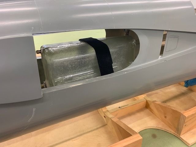
Plate strapped under the tank for dry fit and making sure the tank would fit in with the velcro strap attached. I had to sand a little clearance on the bottom of the intake holes next to the tank to make it fit. I rehearsed the moves needed to get the tank in and keep the bottom off the fuse floor a few times before I put epoxy on for the tack glue in.
Front view of dry fit
The strap was taped on the tank in position and the plate taped to the tank. A small amount of 15 min. epoxy was applied to velcro strips and the CF plate for tack glue in. I wanted to keep it from touching the center strap and I wanted the epoxy to run down and contact the fuse bottom for a tack glue bond.
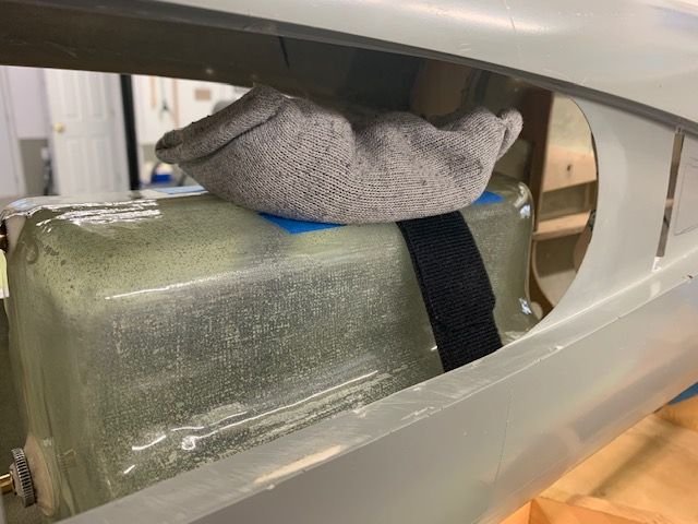
Tank inserted and placed in position with a lead weight sock on top to keep it down.
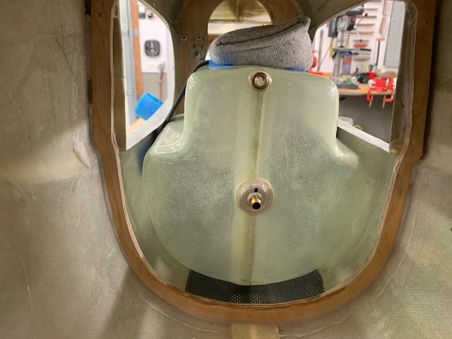
Front view while epoxy curing. It looks crooked in the picture but its really pretty straight.
Side view of tank strap
Two layers of velcro strips were glued to the bottom of the plate with thin CA. These strips act as a 2 layer spacer to hold the plate off the fuse bottom and allow the tank strap to slide under the plate. They also act as an epoxy dam to keep epoxy out of the center section of the plate where the strap must slide through.
Plate strapped under the tank for dry fit and making sure the tank would fit in with the velcro strap attached. I had to sand a little clearance on the bottom of the intake holes next to the tank to make it fit. I rehearsed the moves needed to get the tank in and keep the bottom off the fuse floor a few times before I put epoxy on for the tack glue in.
Front view of dry fit
The strap was taped on the tank in position and the plate taped to the tank. A small amount of 15 min. epoxy was applied to velcro strips and the CF plate for tack glue in. I wanted to keep it from touching the center strap and I wanted the epoxy to run down and contact the fuse bottom for a tack glue bond.
Tank inserted and placed in position with a lead weight sock on top to keep it down.
Front view while epoxy curing. It looks crooked in the picture but its really pretty straight.
Side view of tank strap
08-13-2020, 05:33 PM
#628
Thread Starter
My Feedback: (20)
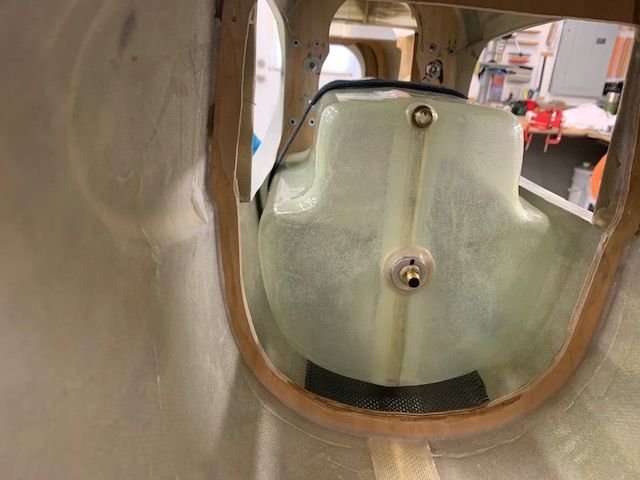
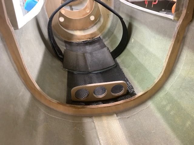
Tank mount tack glued in place for testing
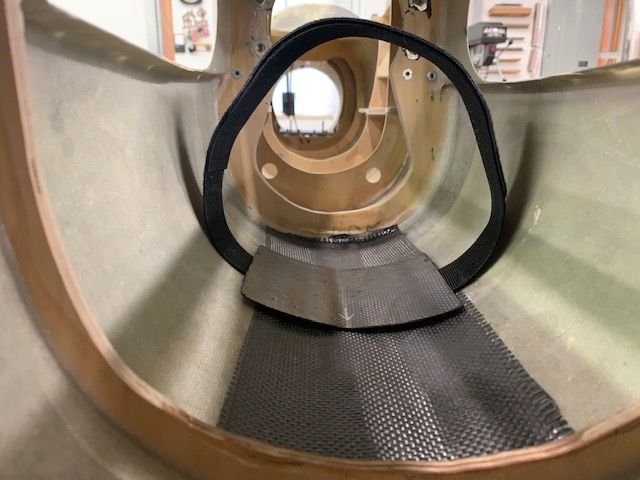
After the epoxy cured I removed tape and pulled the tank out. The Velcro strap was still loose and slid under the plate with just a little friction.
Closer view
Strap removed. After I get the forward tank bumper block in and am sure everything works OK with the strap I will fill in the forward and aft gaps with Six-10 thick epoxy and securely bond the mounting plate to the fuse bottom. Initial testing looks real good so far.
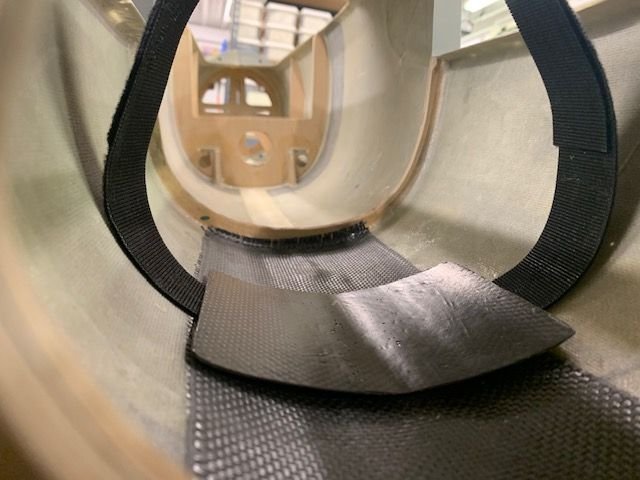
Velcro strap inserts from either side and slides under the plate.
The strap pops out the other side and then over the tank. The strap holds the tank to the fuse bottom. The aft former keeps it from moving aft and a small front bumper block (once installed) with keep if from sliding forward. This method avoids tabs and brackets glued to the tank from breaking off, holds the tank securely, allows easy removal, and gives an unobstructed view of fuel remaining after a flight from front or rear of the tank. This makes it easy to calibrate the CTU for accurate fuel remaining telemetry.
Thanks to Paul Appelbaum for the tank mount idea. Done for the week. Have to pay some "RC dues" this weekend with the grandkids before school starts.
Gary
After the epoxy cured I removed tape and pulled the tank out. The Velcro strap was still loose and slid under the plate with just a little friction.
Closer view
Strap removed. After I get the forward tank bumper block in and am sure everything works OK with the strap I will fill in the forward and aft gaps with Six-10 thick epoxy and securely bond the mounting plate to the fuse bottom. Initial testing looks real good so far.
Velcro strap inserts from either side and slides under the plate.
The strap pops out the other side and then over the tank. The strap holds the tank to the fuse bottom. The aft former keeps it from moving aft and a small front bumper block (once installed) with keep if from sliding forward. This method avoids tabs and brackets glued to the tank from breaking off, holds the tank securely, allows easy removal, and gives an unobstructed view of fuel remaining after a flight from front or rear of the tank. This makes it easy to calibrate the CTU for accurate fuel remaining telemetry.
Thanks to Paul Appelbaum for the tank mount idea. Done for the week. Have to pay some "RC dues" this weekend with the grandkids before school starts.
Gary
Last edited by Viper1GJ; 08-13-2020 at 05:43 PM.
The following 2 users liked this post by Viper1GJ:
Bob_B (08-14-2020),
bonefishfool (08-13-2020)
08-17-2020, 04:31 PM
#629
Thread Starter
My Feedback: (20)
Gluing in tank mount
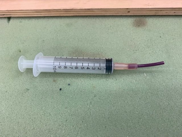
I made a high tech glue injector to get the epoxy under the CF tank mount. Syringe, silicon fuel tube, and 1/8" air line
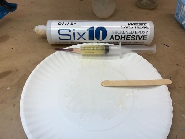
Filled with Six10 epoxy
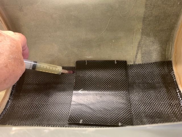
Epoxy injected under the front and aft ends of the CF tank mount till it flooded out.
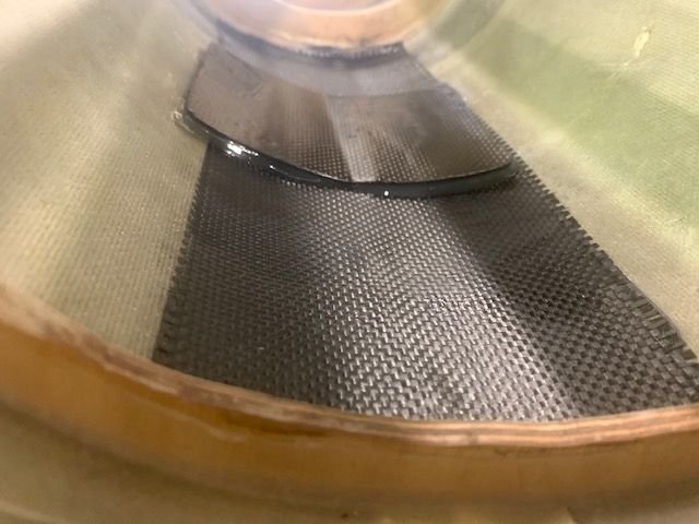
Front side cleaned up
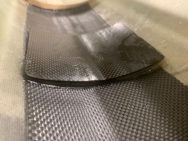
Aft end cleaned up. I ran the Velcro strap through the center section several times to make sure there was no epoxy in the center strap channel.
I made a high tech glue injector to get the epoxy under the CF tank mount. Syringe, silicon fuel tube, and 1/8" air line
Filled with Six10 epoxy
Epoxy injected under the front and aft ends of the CF tank mount till it flooded out.
Front side cleaned up
Aft end cleaned up. I ran the Velcro strap through the center section several times to make sure there was no epoxy in the center strap channel.
The following users liked this post:
bonefishfool (08-17-2020)
08-18-2020, 04:48 PM
#630
Thread Starter
My Feedback: (20)
Balancing stabs
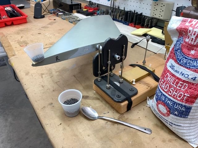
I use a prop balancer to balance the stabs. I taped a mixing cup to the leading edge and filled it with lead shot to balance.
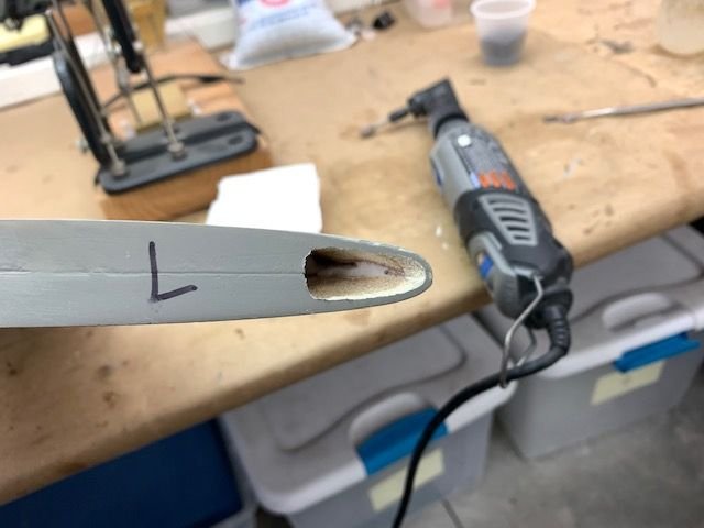
I opened up a hole in the leading edge to put the lead shot in. It took 41 grams or 1.4 oz in each stab. I mixed up some 15 min epoxy with the lead shot. Then I pushed the slurry mix into the hole and tapeed it up with packing tape. Then tilt the leading edge down and let it all roll to the front edge. The tape gives a smooth and flush epoxy finish over the hole.
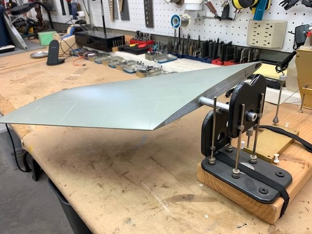
Left side checked.
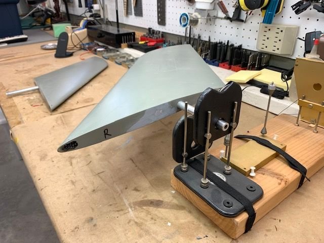
RIght side checked.
I use a prop balancer to balance the stabs. I taped a mixing cup to the leading edge and filled it with lead shot to balance.
I opened up a hole in the leading edge to put the lead shot in. It took 41 grams or 1.4 oz in each stab. I mixed up some 15 min epoxy with the lead shot. Then I pushed the slurry mix into the hole and tapeed it up with packing tape. Then tilt the leading edge down and let it all roll to the front edge. The tape gives a smooth and flush epoxy finish over the hole.
Left side checked.
RIght side checked.
08-18-2020, 05:10 PM
#631
Thread Starter
My Feedback: (20)
Indexing the stab control horn to the stab
First step was drill a 6-32 tap pilot hole in the inside clamp block to accept the indexing set screw
Next was to assemble the stab and horn. I use the molded stab farings on the fuse to establish the stab alignment with the fuse. I have no idea if this is anywhere near where the stabs should be for level flight but it is a place to start and looks the same on both sides.
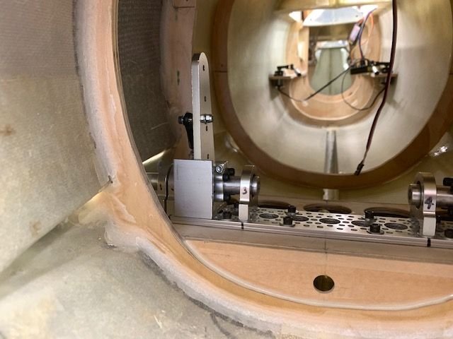
Next was aligning the horns with the base plate. I used a cut off of aluminum angle to align the rear edges of the horns. They are not exactly vertical due to the tapered shape but close enough. At least they are the same on both sides.
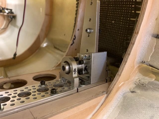
Right side done
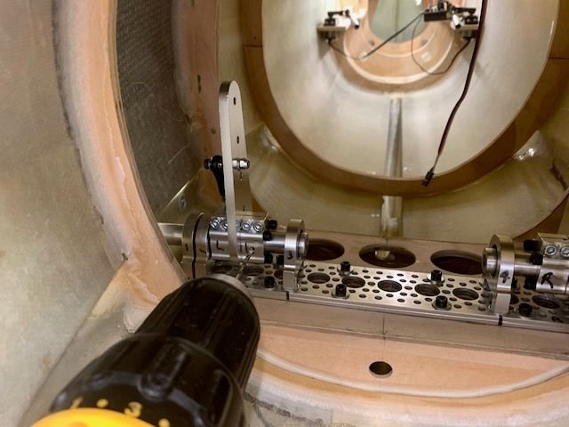
Next the clamp screws were tightened and the 6-32 tap pilot hole was drilled into the stab tube rear edge
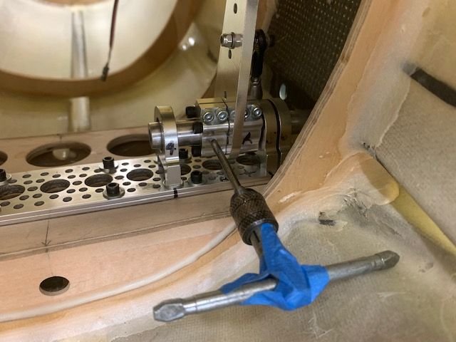
Next the holes were tapped for a 6-32 set screw.
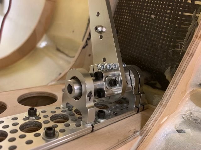
Set screw installed with flat washer and lock washer.
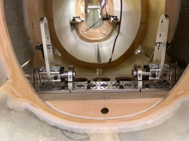
Both sides done. The purpose of the set screw is to be able to set the stab horns in exactly the same position each time they are assembled. The secondary purpose is to keep the stab tube from moving in or out. The servo torque is transferred to the tube by the clamp blocks not the set screw.
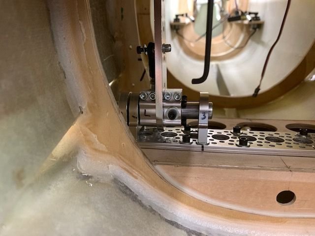
I had to cut off hex wrench to fit into the tight space in order to tighten the clamp bolts for final assembly. Its really bad to have to make special tools to do basic assembly. It's too complicated for my brain!
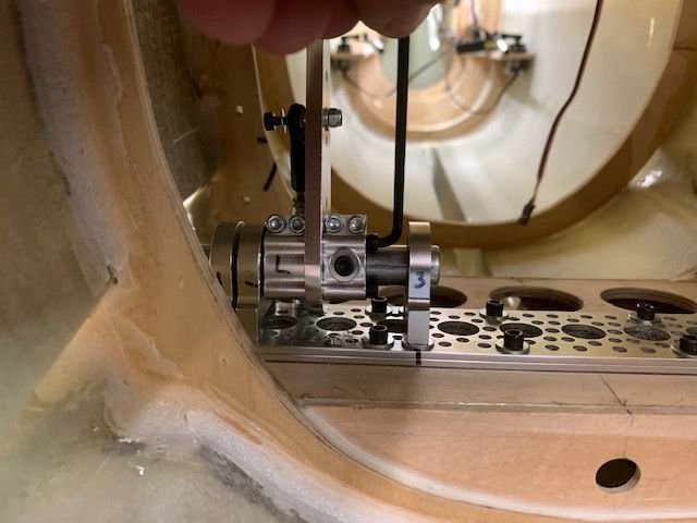
Clamp block bolts have to be tightened after assembly otherwise you cant slide the clamps on the tube.
First step was drill a 6-32 tap pilot hole in the inside clamp block to accept the indexing set screw
Next was to assemble the stab and horn. I use the molded stab farings on the fuse to establish the stab alignment with the fuse. I have no idea if this is anywhere near where the stabs should be for level flight but it is a place to start and looks the same on both sides.
Next was aligning the horns with the base plate. I used a cut off of aluminum angle to align the rear edges of the horns. They are not exactly vertical due to the tapered shape but close enough. At least they are the same on both sides.
Right side done
Next the clamp screws were tightened and the 6-32 tap pilot hole was drilled into the stab tube rear edge
Next the holes were tapped for a 6-32 set screw.
Set screw installed with flat washer and lock washer.
Both sides done. The purpose of the set screw is to be able to set the stab horns in exactly the same position each time they are assembled. The secondary purpose is to keep the stab tube from moving in or out. The servo torque is transferred to the tube by the clamp blocks not the set screw.
I had to cut off hex wrench to fit into the tight space in order to tighten the clamp bolts for final assembly. Its really bad to have to make special tools to do basic assembly. It's too complicated for my brain!
Clamp block bolts have to be tightened after assembly otherwise you cant slide the clamps on the tube.
08-18-2020, 05:14 PM
#632
Thread Starter
My Feedback: (20)
Indexing the stab control horn to the stab
First step was drill a 6-32 tap pilot hole in the inside clamp block to accept the indexing set screw
Next was to assemble the stab and horn. I use the molded stab farings on the fuse to establish the stab alignment with the fuse. I have no idea if this is anywhere near where the stabs should be for level flight but it is a place to start and looks the same on both sides.
Next was aligning the horns with the base plate. I used a cut off of aluminum angle to align the rear edges of the horns. They are not exactly vertical due to the tapered shape but close enough. At least they are the same on both sides.
Right side done
Next the clamp screws were tightened and the 6-32 tap pilot hole was drilled into the stab tube rear edge
Next the holes were tapped for a 6-32 set screw.
Set screw installed with flat washer and lock washer.
Both sides done. The purpose of the set screw is to be able to set the stab horns in exactly the same position each time they are assembled. The secondary purpose is to keep the stab tube from moving in or out. The servo torque is transferred to the tube by the clamp blocks not the set screw.
I had to cut off hex wrench to fit into the tight space in order to tighten the clamp bolts for final assembly. Its really bad to have to make special tools to do basic assembly. It's too complicated for my brain!
Clamp block bolts have to be tightened after assembly otherwise you cant slide the clamps on the tube.
08-18-2020, 05:27 PM
#633
Thread Starter
My Feedback: (20)
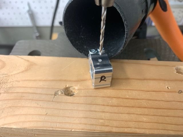
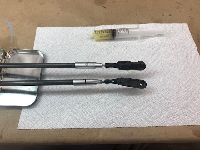
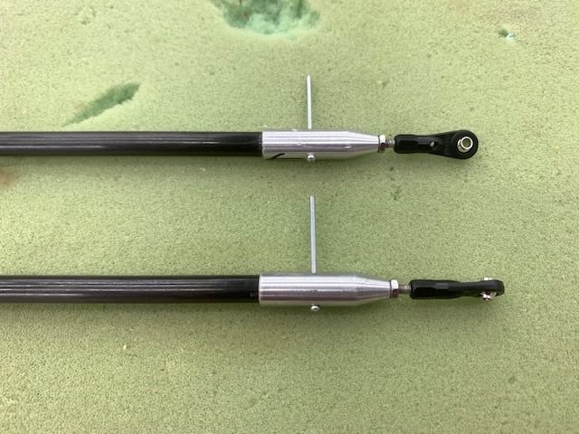
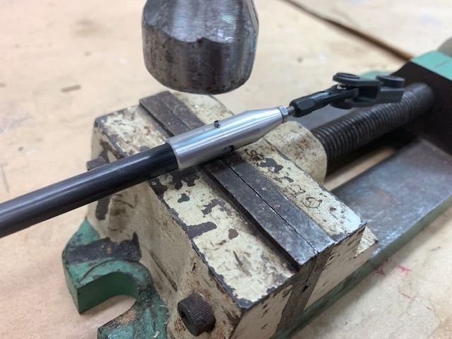
Assembling Carbon Fiber Pushrods
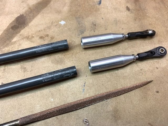
I got these really cool 8mm CF pushrod ends from Phil Clark at FIghterAces in the UK. They are machined aluminum and have 3mm threaded rod ends and 3mm ball links. First I scuffed the ends of the CF rods with the corner of a perma grit triangle file.
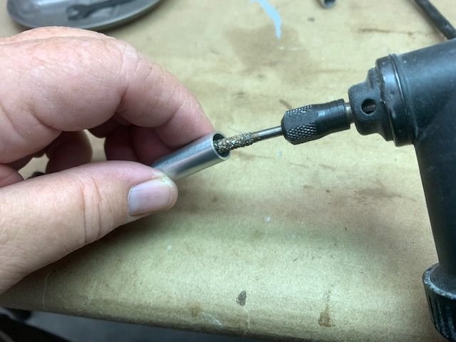
Next I scuffed the insides of the rod ends with a perma grit bit on low speed. The idea was to scratch the inside surface to provide grip for the epoxy.
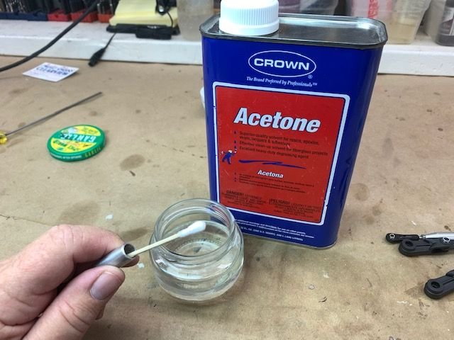
Next I cleaned the insides out with acetone. There was lots of residue and oil from the machining process inside
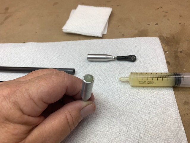
Next I filled the inside with Six10 epoxy
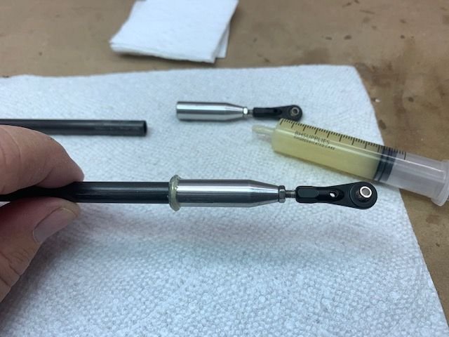
Pushed in and rotated the CF rod, then removed and pushed in again. Overflow pushed out on outside of rod
Excess epoxy cleaned off and ready for overnight cure. Rod ends will be drilled for a through safety bolt after cured on both ends.
I got these really cool 8mm CF pushrod ends from Phil Clark at FIghterAces in the UK. They are machined aluminum and have 3mm threaded rod ends and 3mm ball links. First I scuffed the ends of the CF rods with the corner of a perma grit triangle file.
Next I scuffed the insides of the rod ends with a perma grit bit on low speed. The idea was to scratch the inside surface to provide grip for the epoxy.
Next I cleaned the insides out with acetone. There was lots of residue and oil from the machining process inside
Next I filled the inside with Six10 epoxy
Pushed in and rotated the CF rod, then removed and pushed in again. Overflow pushed out on outside of rod
Excess epoxy cleaned off and ready for overnight cure. Rod ends will be drilled for a through safety bolt after cured on both ends.
08-18-2020, 05:36 PM
#634
Thread Starter
My Feedback: (20)
Fuel tank forward stop
Cut out an forward fuel tank stop to keep it from sliding forward. Dry fit and then glued in with 15 min epoxy.
Stop plate just in front of tank.
Fillet of Six10 epoxy around base.
Cut out an forward fuel tank stop to keep it from sliding forward. Dry fit and then glued in with 15 min epoxy.
Stop plate just in front of tank.
Fillet of Six10 epoxy around base.
08-18-2020, 05:46 PM
#635
Thread Starter
My Feedback: (20)
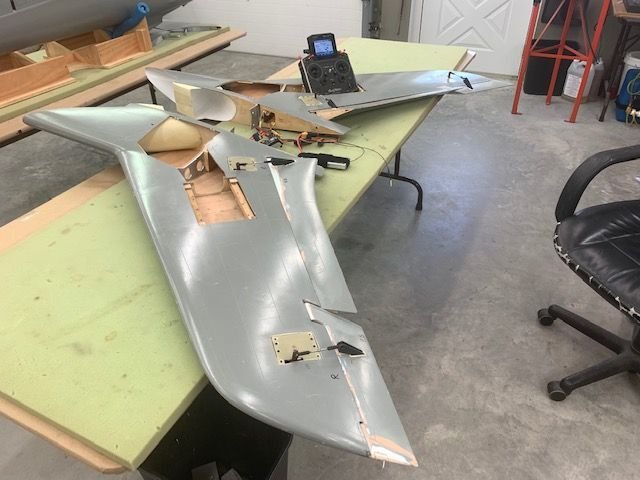
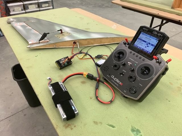
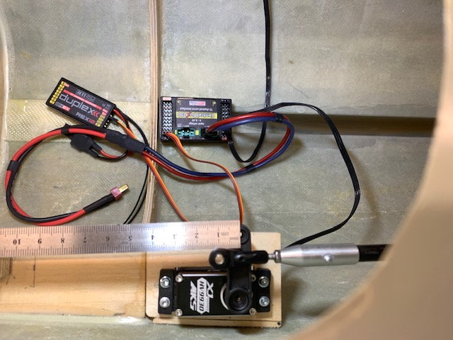
Receiver and battery connected for the 1st time!
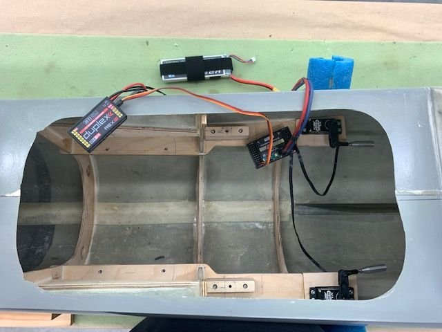
This picture shows nothing except for connecting a receiver and battery to the elevator servos to set sub trims to align the servo arms. That's not a big deal in its self. However, I thought it was a moment to stare it.
I'M FINALLY GETTING CLOSE ENOUGH TO FINISHING THE SCRATCH BUILD STUFF THAT I CAN ACTUALLY PLUG IN A SERVO AND WATCH IT DO SOMETHING. MAYBE JUST MAYBE IT IS COMING TOGETHER. WOW!

 08-19-2020, 05:23 AM
#638
It's been a wonderful journey watching you progress through the good and bad w/ this model! Congratulations and looking forward to more to come......it's been my favorite thread on this forum!
 08-19-2020, 07:55 AM
#641

That�s some thing that I would normally do too but with the amount of Six-10 in the tube I don�t think it will be a problem.
08-19-2020, 04:57 PM
#642
Thread Starter
My Feedback: (20)
Thanks for the compliment guys, I really appreciate it and you guys are motivational too. It's starting to feel more like a model airplane now instead of a boat anchor!
Tom, I planned to have about 1" of solid Six10 epoxy in each end to keep the ends from splitting. That's why I filled up the cup before pushing the rod in. Most of the squeeze out was from epoxy I put on the outside of the rod before I stuck it in so the inside should be filled slightly beyond the edge of the aluminum. I'll find out when I drill through it for the cross pin. Thanks, G.
Tom, I planned to have about 1" of solid Six10 epoxy in each end to keep the ends from splitting. That's why I filled up the cup before pushing the rod in. Most of the squeeze out was from epoxy I put on the outside of the rod before I stuck it in so the inside should be filled slightly beyond the edge of the aluminum. I'll find out when I drill through it for the cross pin. Thanks, G.
08-19-2020, 05:12 PM
#643
Thread Starter
My Feedback: (20)
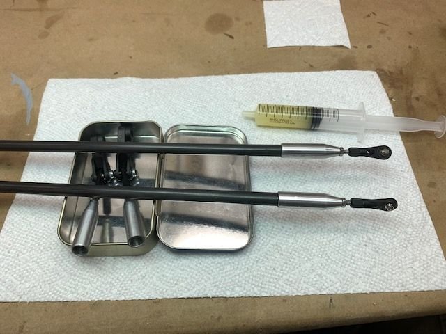
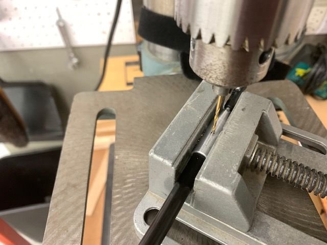
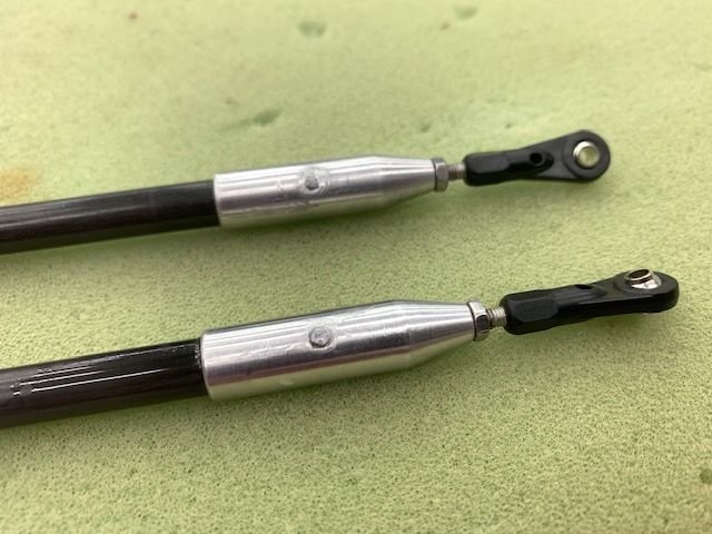
Finishing the CF pushrods
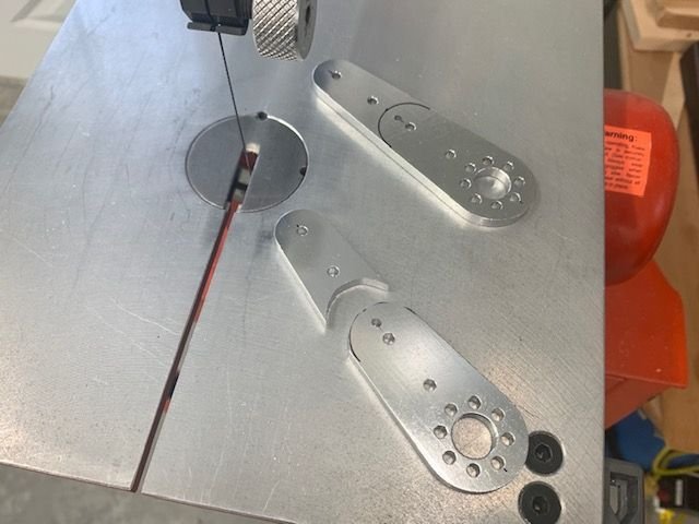
Stab control horns cut to size and sanded smooth
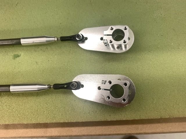
3mm ball joints bolted to the horns and clamp brackets assembled
Stab horns mounted and clamped in and stabs taped to fuse farings to hold them level for marking the pushrod length
Pushrods marked at end of aluminum caps and then 27mm added to the length for insert into the pushrod ends
CF rods cut, scuffed, cleaned, and epoxied in the aluminum rod ends as described in above post. My granddaughter asked for some extra epoxy for her project so I mixed extra and gave her the remaining. I did not see the results yet but I'm sure I will!
Stab control horns cut to size and sanded smooth
3mm ball joints bolted to the horns and clamp brackets assembled
Stab horns mounted and clamped in and stabs taped to fuse farings to hold them level for marking the pushrod length
Pushrods marked at end of aluminum caps and then 27mm added to the length for insert into the pushrod ends
CF rods cut, scuffed, cleaned, and epoxied in the aluminum rod ends as described in above post. My granddaughter asked for some extra epoxy for her project so I mixed extra and gave her the remaining. I did not see the results yet but I'm sure I will!
08-19-2020, 05:24 PM
#644
Thread Starter
My Feedback: (20)
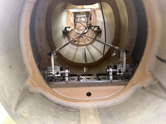
Wiring the wings
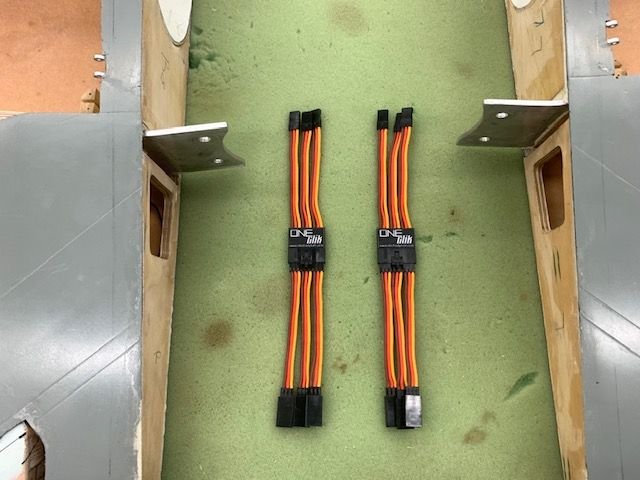
I'm using these One Click connectors from Electrodynamics on the wings for ailerons, flaps, and gear door servos
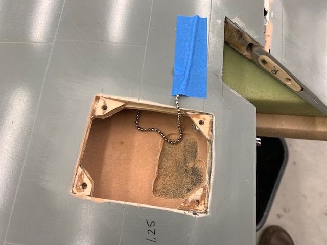
My favorite way to snake a wire through a wing is to use a long ceiling fan chain and gravity drop it through the openings. It always seems to find it's way through even in a curved foam channel.
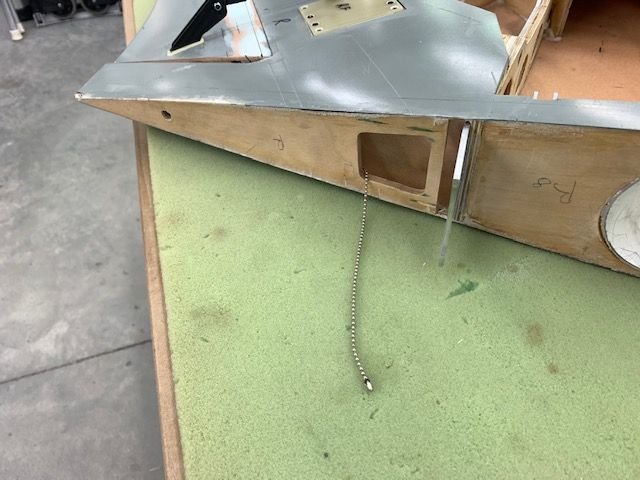
This one was easy even though there was no prepared channel.
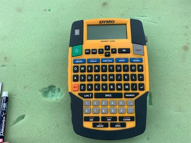
This is the label maker I use for servo heat shrink markings. I use 1/2" shrink tube. It easily fits over the small ends and with a little stretch fits over the big ends of servo extensions. Shrinks tight on all wires.
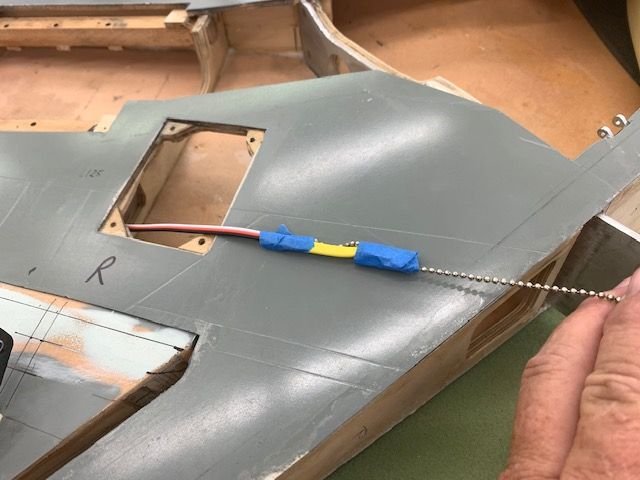
Aileron wire snaked through with the pull chain
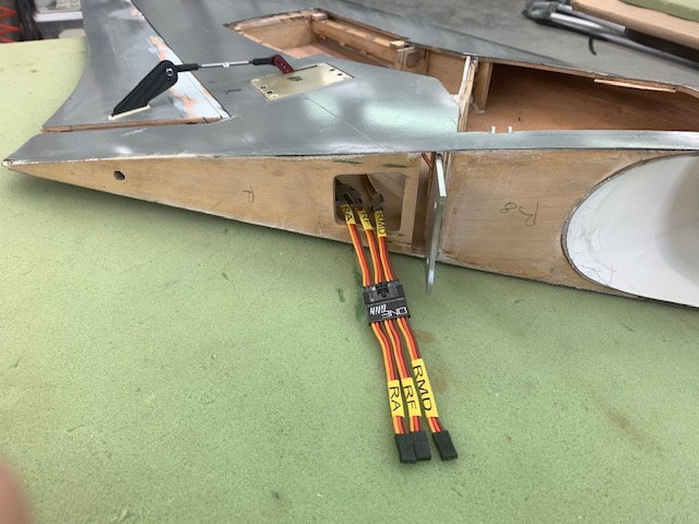
All connectors labeled. I wish I had learned about the shrink labels years ago.
Success! I have ailerons wiggling and flaps flapping! Making progress!
I'm using these One Click connectors from Electrodynamics on the wings for ailerons, flaps, and gear door servos
My favorite way to snake a wire through a wing is to use a long ceiling fan chain and gravity drop it through the openings. It always seems to find it's way through even in a curved foam channel.
This one was easy even though there was no prepared channel.
This is the label maker I use for servo heat shrink markings. I use 1/2" shrink tube. It easily fits over the small ends and with a little stretch fits over the big ends of servo extensions. Shrinks tight on all wires.
Aileron wire snaked through with the pull chain
All connectors labeled. I wish I had learned about the shrink labels years ago.
Success! I have ailerons wiggling and flaps flapping! Making progress!
The following 2 users liked this post by Viper1GJ:
Desertlakesflying (08-20-2020),
[email protected] (08-19-2020)
 08-24-2020, 05:26 PM
#646
Thread Starter
My Feedback: (20)
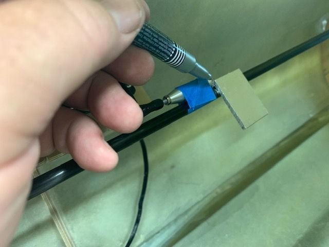
Cross pinning stab pushrods
Pushrod ends drilled
Pin from small pop rivit used to cross pin the pushrod cap to the CF tube. I found that each end was filled with solid epoxy as planned so I think they should not split on the inside.
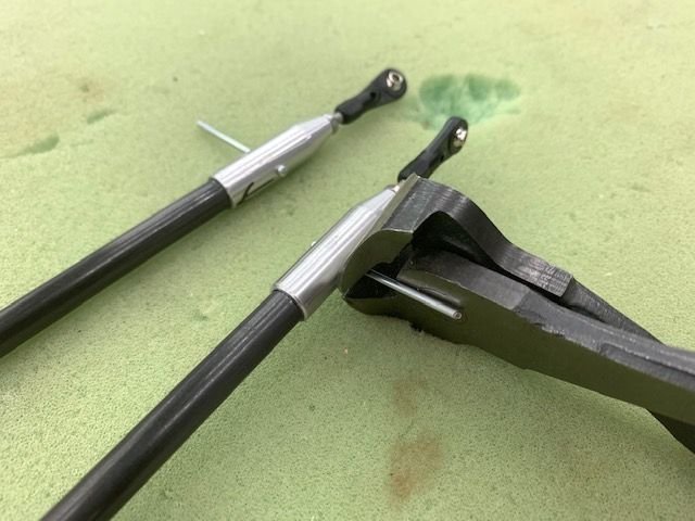
Aluminum pins cut off
Cut off end hammered and peened flat to hold the pin in
After peening thin CA glue was applied to both ends
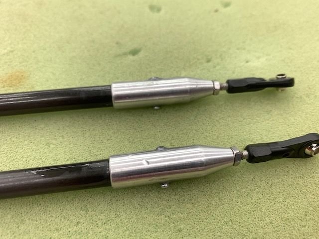
After the thin CA a drop of medium CA was applied to each end to make a smooth rounded bump and lock the pins in.
Pushrod ends drilled
Pin from small pop rivit used to cross pin the pushrod cap to the CF tube. I found that each end was filled with solid epoxy as planned so I think they should not split on the inside.
Aluminum pins cut off
Cut off end hammered and peened flat to hold the pin in
After peening thin CA glue was applied to both ends
After the thin CA a drop of medium CA was applied to each end to make a smooth rounded bump and lock the pins in.
08-26-2020, 03:50 PM
#647
Thread Starter
My Feedback: (20)
Push rod too long!
Well I screwed the pooch on this one. Don't know what, how, when, or where I screwed up but one push rod is 10mm too long. I don't know if the sub trim was off, the arm was on wrong spline, or blah, blah, blah, blah. There is no amount of programming endpoints, sub trim, clevis adjustment etc that will fix this and keep symetrical movement on both stabs. My only choice is to fix it. The only problem is it all glued in and pinned inside the aluminum cap, and will not come out easily. I'm thinking about cutting the 8mm CF tube, splicing inside with a 6mm tube, and sliding a 10mm carbon tube over the splice and gluing everything back together. It will be fine except it will look like a 3rd grader made it. Arrrgh!
I'll have to wait till next week. Grandkids flew in from Texas for the week so I will stew on it for a few days. Arrgh!
08-26-2020, 04:03 PM
#648

Cross pinning stab pushrods
Pushrod ends drilled
Pin from small pop rivit used to cross pin the pushrod cap to the CF tube. I found that each end was filled with solid epoxy as planned so I think they should not split on the inside.
Aluminum pins cut off
Cut off end hammered and peened flat to hold the pin in
After peening thin CA glue was applied to both ends
After the thin CA a drop of medium CA was applied to each end to make a smooth rounded bump and lock the pins in.
08-26-2020, 05:10 PM
#650

Join Date: Dec 2005
Location: phoenix,
AZ
Posts: 32
Likes: 0
Received 0 Likes
on
0 Posts
Push rod too long!
Well I screwed the pooch on this one. Don't know what, how, when, or where I screwed up but one push rod is 10mm too long. I don't know if the sub trim was off, the arm was on wrong spline, or blah, blah, blah, blah. There is no amount of programming endpoints, sub trim, clevis adjustment etc that will fix this and keep symetrical movement on both stabs. My only choice is to fix it. The only problem is it all glued in and pinned inside the aluminum cap, and will not come out easily. I'm thinking about cutting the 8mm CF tube, splicing inside with a 6mm tube, and sliding a 10mm carbon tube over the splice and gluing everything back together. It will be fine except it will look like a 3rd grader made it. Arrrgh!
I'll have to wait till next week. Grandkids flew in from Texas for the week so I will stew on it for a few days. Arrgh!
Well I screwed the pooch on this one. Don't know what, how, when, or where I screwed up but one push rod is 10mm too long. I don't know if the sub trim was off, the arm was on wrong spline, or blah, blah, blah, blah. There is no amount of programming endpoints, sub trim, clevis adjustment etc that will fix this and keep symetrical movement on both stabs. My only choice is to fix it. The only problem is it all glued in and pinned inside the aluminum cap, and will not come out easily. I'm thinking about cutting the 8mm CF tube, splicing inside with a 6mm tube, and sliding a 10mm carbon tube over the splice and gluing everything back together. It will be fine except it will look like a 3rd grader made it. Arrrgh!
I'll have to wait till next week. Grandkids flew in from Texas for the week so I will stew on it for a few days. Arrgh!