1/6 F-105 Build Thread
 06-15-2020, 03:03 PM
#601

Thread Starter
My Feedback: (20)
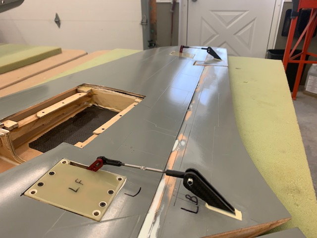
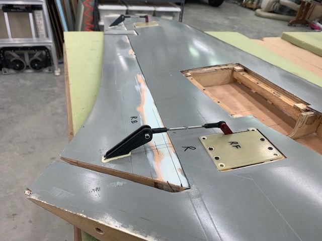
Drag Chute Door Latch
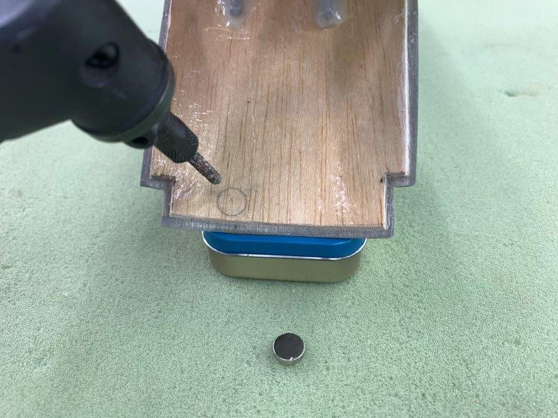
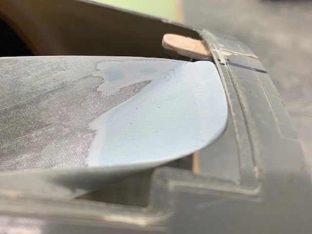
Drag chute door magnet placed off center to clear the chute deploy tube.
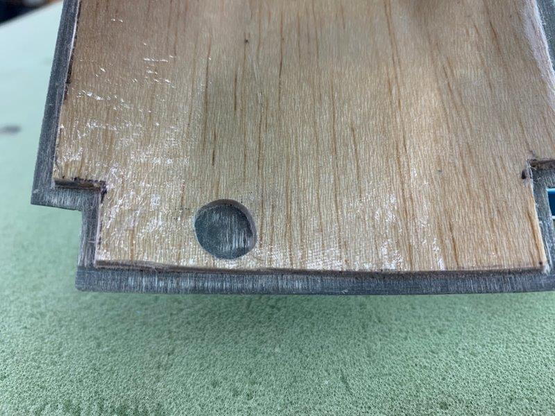
Circle marked on door and routed out with Dremel perma grit and then a flat bottom mill bit. Magnet epoxied in place.
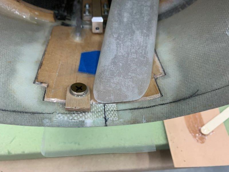
A small piece of plastic was used to keep the epoxy for the latch from sticking to the door.

If the magnets were touching they were too strong and it was too hard to push the door open. I put the latch magnet on the bottom of the 1/8" ply holder to separate them. This reduced the force needed to push open the door. Hopefully it will allow the air ram to push the door open and eject the chute but still keep the door closed in the air flow across the tail.
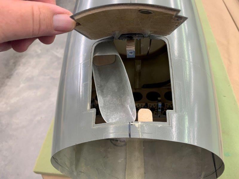
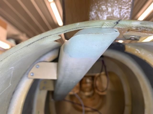
View from the top. Door magnet recessed into the door and plywood latch magnet holder with magnet on the bottom. Time for the first test.
I plan to attached the air ram to the compressed air supply and see if it will open the door and eject the chute. I will place a floor blower in front of the fuse and see if I can get the chute to fully inflate in the shop. Hopefully if it works I can get some photos.
Drag chute door magnet placed off center to clear the chute deploy tube.
Circle marked on door and routed out with Dremel perma grit and then a flat bottom mill bit. Magnet epoxied in place.
A small piece of plastic was used to keep the epoxy for the latch from sticking to the door.
If the magnets were touching they were too strong and it was too hard to push the door open. I put the latch magnet on the bottom of the 1/8" ply holder to separate them. This reduced the force needed to push open the door. Hopefully it will allow the air ram to push the door open and eject the chute but still keep the door closed in the air flow across the tail.
View from the top. Door magnet recessed into the door and plywood latch magnet holder with magnet on the bottom. Time for the first test.
I plan to attached the air ram to the compressed air supply and see if it will open the door and eject the chute. I will place a floor blower in front of the fuse and see if I can get the chute to fully inflate in the shop. Hopefully if it works I can get some photos.
 06-15-2020, 05:31 PM
#602


Even if it doesn’t work, the fan idea will help clean out the workshop lol.
looking good! I added chute to my avonds f-104 years ago and enjoyed using it. Initially i had it set up with the D4S electronics but in the end i just simplified it with single switch and a servo delay from the door to the air ram.
heres an old clip.
looking good! I added chute to my avonds f-104 years ago and enjoyed using it. Initially i had it set up with the D4S electronics but in the end i just simplified it with single switch and a servo delay from the door to the air ram.
heres an old clip.
06-16-2020, 04:34 PM
#603
06-16-2020, 04:58 PM
#604
Thread Starter
My Feedback: (20)
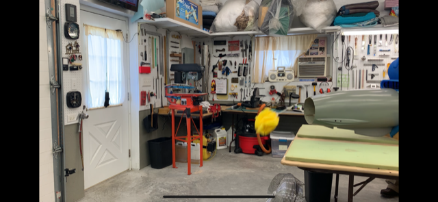
Successful Drag Chute Test
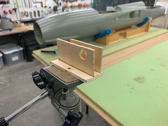
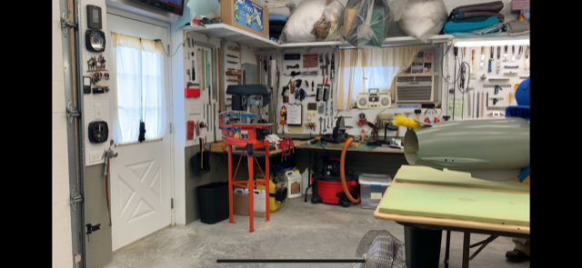
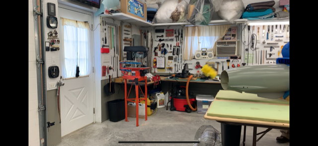
I wanted to make a video of the drag chute testing so I modified my 40 year old tripod to hold a modern iPhone.
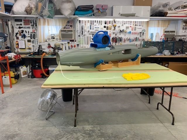
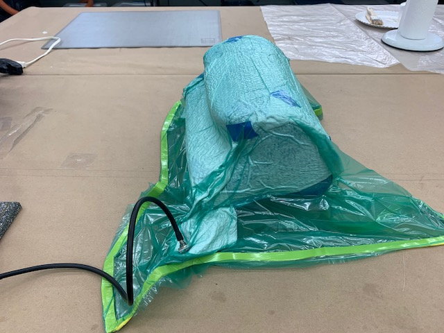
The basic test setup, floor fan on top of fuse, fan on floor, and chute layout.

Chute packed in tube and connected to release with nylon cord. Air ram connected to shop compressor with blow gun and sports ball needle stuck into the air tube connected to air ram with a push to connect coupler. Cute deployed by pulling blow gun trigger.
First couple of tests had some hangup and fowling on the lip of the fuse at trailing edge of the tube. I had thought this would be a problem so I built up a smooth ramp using Icing body putty and made the transition smooth.
The ramp was about 1/8" thick to raise up to the edge of the fuse lip
Finally got consistent deployment each time. Some screen shots of chute deployment. Air ram had no problem pushing open the door and blowing out the chute
Chute clears the tail and hits windstream
Chute hit wind stream and starts to unfold
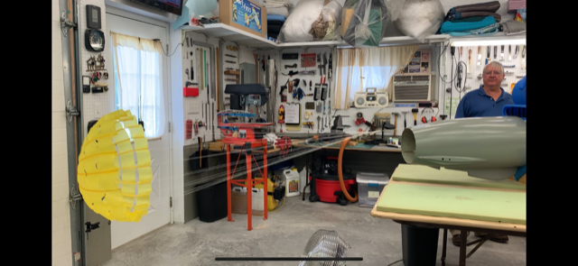
Full deployment! I was really pleased with the air ram deployment and door operation. It took a couple of weeks to dream it up and fabricate the parts but I'm glad I did it now. It will really add to the realism of the whole model. Thanks for all the encouragement and suggestions.
Next up is laying up the fuel tank and installing elevator servo mounts and pushrods. More to come...
Gary
I wanted to make a video of the drag chute testing so I modified my 40 year old tripod to hold a modern iPhone.
The basic test setup, floor fan on top of fuse, fan on floor, and chute layout.
Chute packed in tube and connected to release with nylon cord. Air ram connected to shop compressor with blow gun and sports ball needle stuck into the air tube connected to air ram with a push to connect coupler. Cute deployed by pulling blow gun trigger.
First couple of tests had some hangup and fowling on the lip of the fuse at trailing edge of the tube. I had thought this would be a problem so I built up a smooth ramp using Icing body putty and made the transition smooth.
The ramp was about 1/8" thick to raise up to the edge of the fuse lip
Finally got consistent deployment each time. Some screen shots of chute deployment. Air ram had no problem pushing open the door and blowing out the chute
Chute clears the tail and hits windstream
Chute hit wind stream and starts to unfold
Full deployment! I was really pleased with the air ram deployment and door operation. It took a couple of weeks to dream it up and fabricate the parts but I'm glad I did it now. It will really add to the realism of the whole model. Thanks for all the encouragement and suggestions.
Next up is laying up the fuel tank and installing elevator servo mounts and pushrods. More to come...
Gary
The following 3 users liked this post by Viper1GJ:
06-17-2020, 04:53 PM
#607
Thread Starter
My Feedback: (20)
Thanks for the compliments guys!
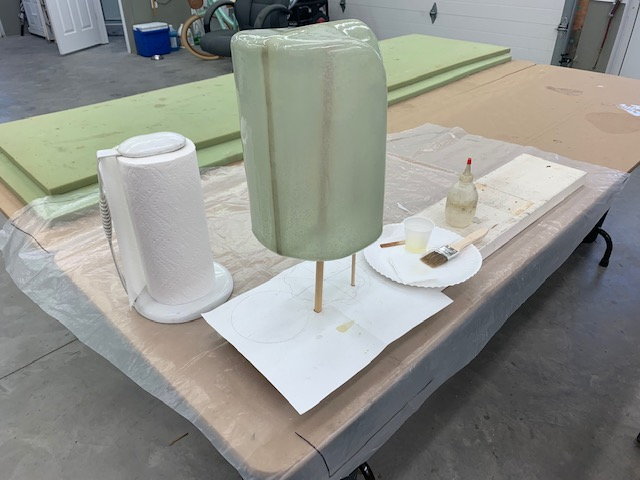
Back to the fuel tank layup
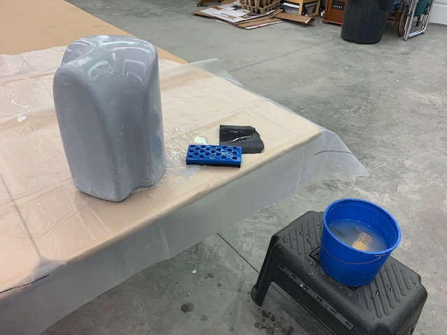
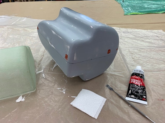
Final wet sanding of primer coats.
Plug wet sanded with 220, 400, 600, and polished with 1200 grit wet sandpaper. IT feels real smooth now.
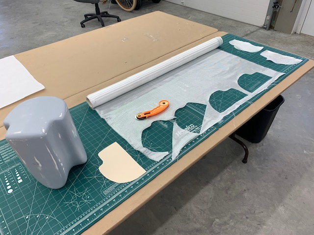
Template for end pieces made to allow easy cutting on a 45 degree bias. I read that some where and it sounded like a good idea. Layup plan is surface coat of epoxy, 3 oz, 6 oz, 3 oz, 6 oz, 3 oz, 3 oz for six layers
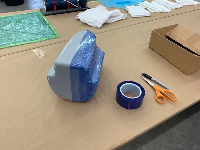
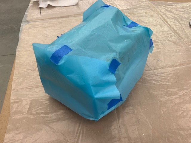
All glass, peel ply, perforated release film, and breather cloth cut and ready. Vacuum bag ready. Flash release tape used to tape off the plug on the center line.
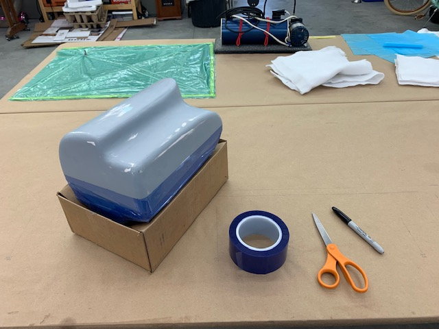
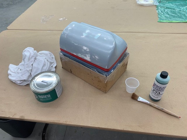
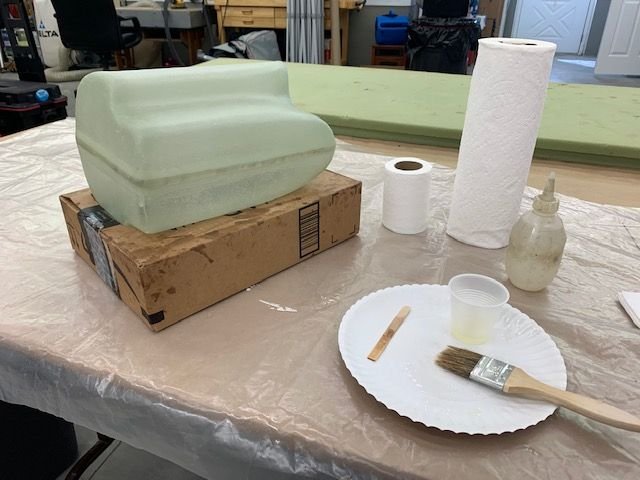
Cardboard box used to for a base for layup
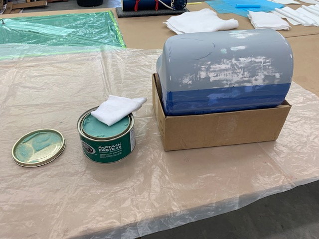
4 coats of Partall paste wax make it feel pretty slick
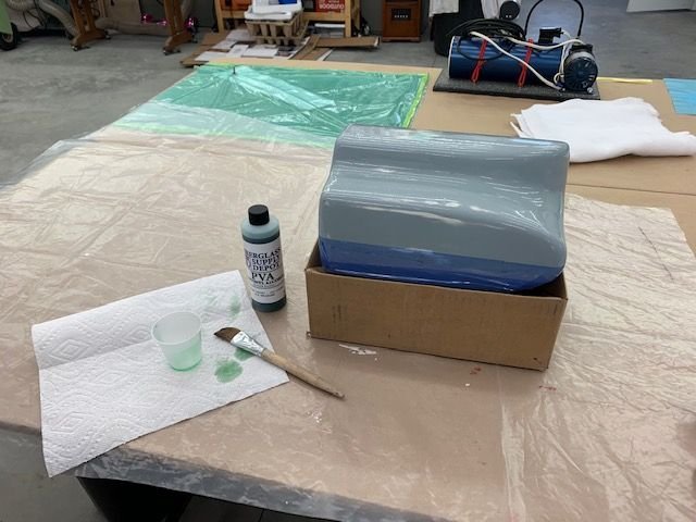
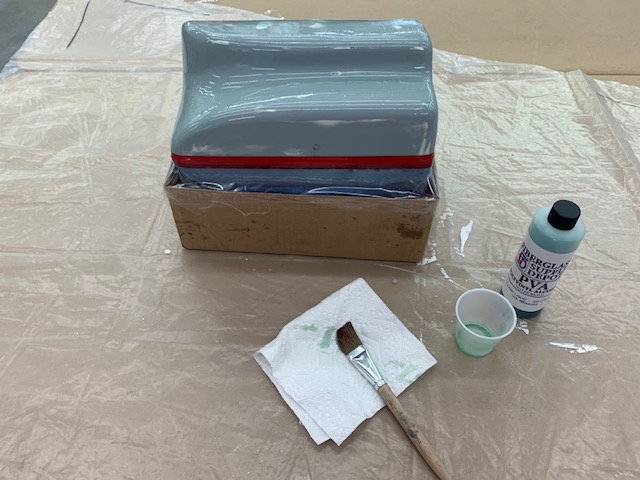
One coat of PVA brushed on. I just did not want to fool with the sprayer. It didn't feel slick any more. Hope this stuff works.
 \\
\\
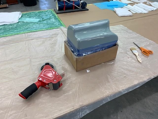
Plug taped to the box for stability
All 6 layers of glass on and wetted out
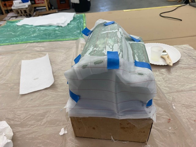
Peel ply added on top.
Perforated release film added on top of peel ply
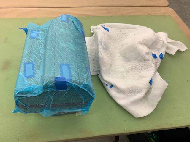
Breather cloth added on top of release film and stuffed into vacuum bag. This is the first time I've used the sealing tape on the bag. Had trouble with getting wrinkles and leaks. Next time I'll tape the bag plastic down so it won't pucker up and wrinkle on the sealing tape. Still learning this stuff.
Now if it will just come off the plug tomorrow! This is my first attempt at making a mold. Fingers crossed.
Back to the fuel tank layup
Final wet sanding of primer coats.
Plug wet sanded with 220, 400, 600, and polished with 1200 grit wet sandpaper. IT feels real smooth now.
Template for end pieces made to allow easy cutting on a 45 degree bias. I read that some where and it sounded like a good idea. Layup plan is surface coat of epoxy, 3 oz, 6 oz, 3 oz, 6 oz, 3 oz, 3 oz for six layers
All glass, peel ply, perforated release film, and breather cloth cut and ready. Vacuum bag ready. Flash release tape used to tape off the plug on the center line.
Cardboard box used to for a base for layup
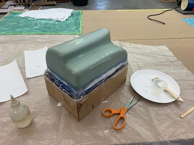
4 coats of Partall paste wax make it feel pretty slick
One coat of PVA brushed on. I just did not want to fool with the sprayer. It didn't feel slick any more. Hope this stuff works.
\\Plug taped to the box for stability
All 6 layers of glass on and wetted out
Peel ply added on top.
Perforated release film added on top of peel ply
Breather cloth added on top of release film and stuffed into vacuum bag. This is the first time I've used the sealing tape on the bag. Had trouble with getting wrinkles and leaks. Next time I'll tape the bag plastic down so it won't pucker up and wrinkle on the sealing tape. Still learning this stuff.
Now if it will just come off the plug tomorrow! This is my first attempt at making a mold. Fingers crossed.
Last edited by Viper1GJ; 06-17-2020 at 05:00 PM.
06-18-2020, 04:02 PM
#610
Thread Starter
My Feedback: (20)
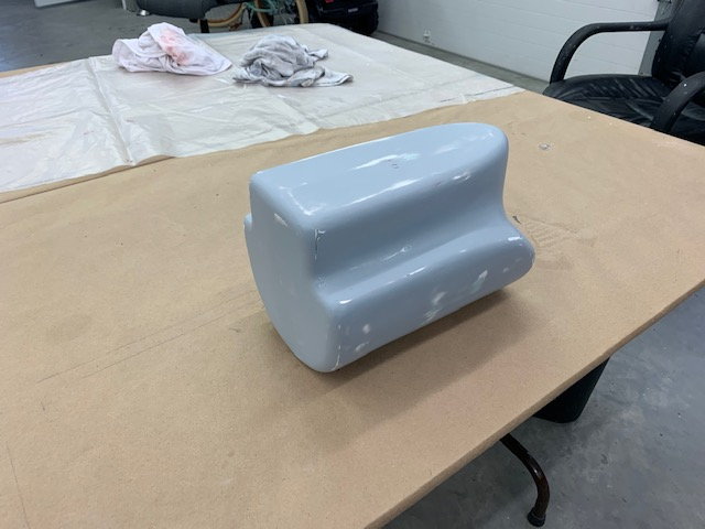
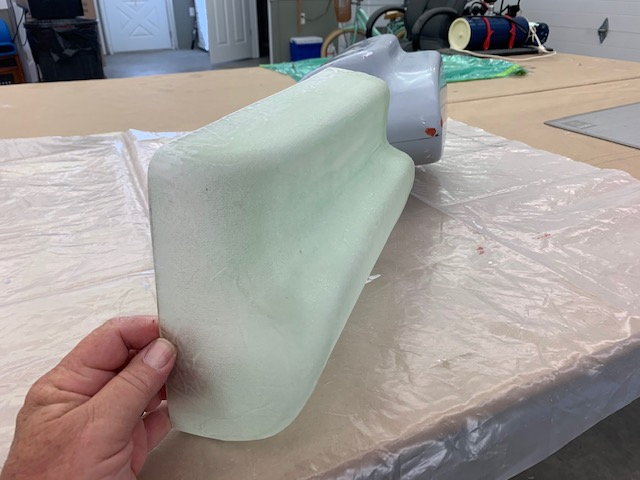
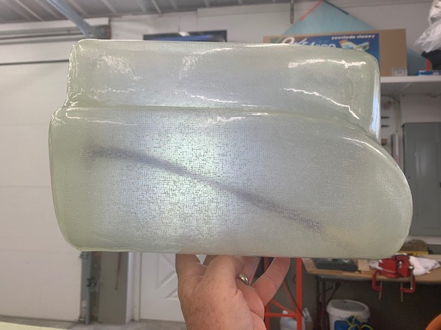
Tank half removed from mold.

With great anticipation I went to the shop this morning to see what I had. Pulled the tank from the vacuum bag and the fun started. First the breather cloth came off pretty easy with the perforated release film (blue stuff) under it.
Next was the peel ply. It was saturated with epoxy so it was more of a challenge but the pliers really helped grip it and peel it off. Then the fun started. I trimmed off the glass edges as close to the tape line as possible with some small lexan scissors, Next I blew compressed air under the edge of the layup and could see the glass lift off the surface of the plug is most areas. But it would not budge. I found it was solid on the top and bottom corners on the front and back of the tank. I think the problem was too small of corner radius and not enough negative draft angle and it was locked on. I poked, prodded, and pulled with several tools but no luck. After about an hour I thought it was a lost cause getting the part off the plug. It was depressing.
I finally decided to try the Dremel cut off wheel to score the glass right up next to the line and pull off the glass with the pliers. And it started to work.
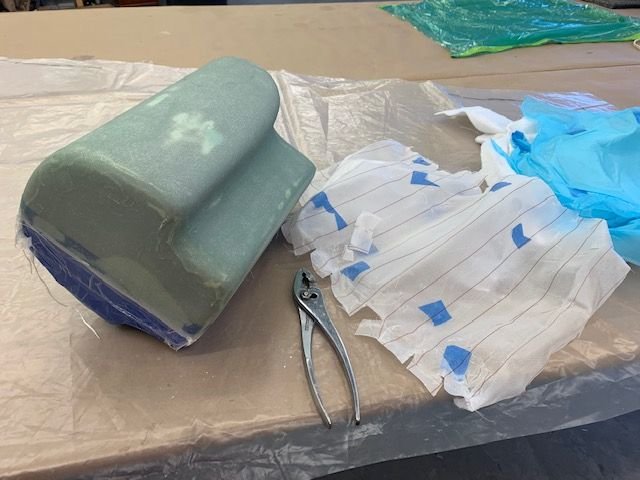
This is the moment it popped off. I was like a 3 year old kid the just got a candy bar! It worked. I was able to get it off by pulling at the rear of the tank and poof, off it came. I can see my surface prep was good and was not the issue. It was the tight corner radius and poor plug design. Well, it was my first try and I'm learning a lot. Now I understand what Paul meant when he said plug design was everything. Anyway I got this far so I will try it again on the next half.
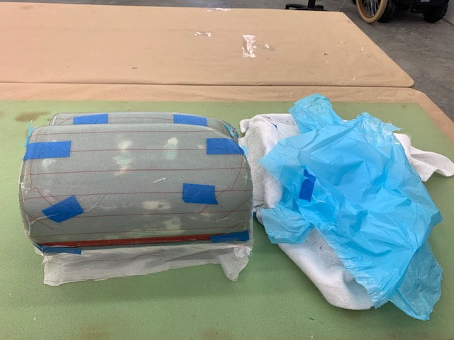
First, I marked the centerline of the plug before I removed the blue flash release tape
Next I marked the inside of the tank half on the tape line for trimming the edge

Ready to trim
I found some small cuts on the plug where the cutoff wheel went too deep. None went thru the glass surface on the plug so I just put some glazing putty in the nicks and will sand it smooth again.
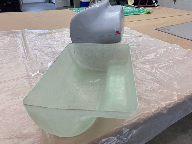
Tank half after trimming and sanding the edges
Seemed to be a usable part
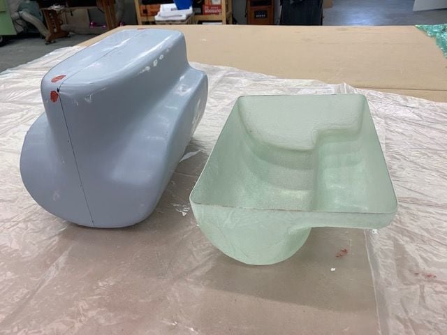
Plug ready to sand and re-wax for next half.
Had another pop up weekend trip so it will be next week before I can lay up the next part. More adventure to come...
With great anticipation I went to the shop this morning to see what I had. Pulled the tank from the vacuum bag and the fun started. First the breather cloth came off pretty easy with the perforated release film (blue stuff) under it.
Next was the peel ply. It was saturated with epoxy so it was more of a challenge but the pliers really helped grip it and peel it off. Then the fun started. I trimmed off the glass edges as close to the tape line as possible with some small lexan scissors, Next I blew compressed air under the edge of the layup and could see the glass lift off the surface of the plug is most areas. But it would not budge. I found it was solid on the top and bottom corners on the front and back of the tank. I think the problem was too small of corner radius and not enough negative draft angle and it was locked on. I poked, prodded, and pulled with several tools but no luck. After about an hour I thought it was a lost cause getting the part off the plug. It was depressing.
I finally decided to try the Dremel cut off wheel to score the glass right up next to the line and pull off the glass with the pliers. And it started to work.
This is the moment it popped off. I was like a 3 year old kid the just got a candy bar! It worked. I was able to get it off by pulling at the rear of the tank and poof, off it came. I can see my surface prep was good and was not the issue. It was the tight corner radius and poor plug design. Well, it was my first try and I'm learning a lot. Now I understand what Paul meant when he said plug design was everything. Anyway I got this far so I will try it again on the next half.
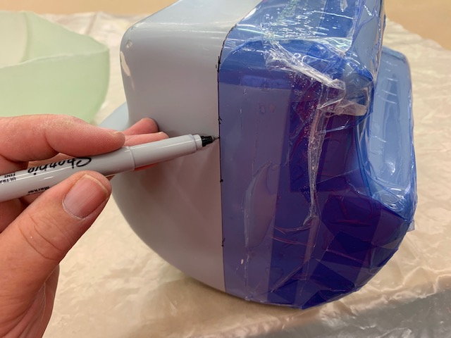
First, I marked the centerline of the plug before I removed the blue flash release tape
Next I marked the inside of the tank half on the tape line for trimming the edge
Ready to trim
I found some small cuts on the plug where the cutoff wheel went too deep. None went thru the glass surface on the plug so I just put some glazing putty in the nicks and will sand it smooth again.
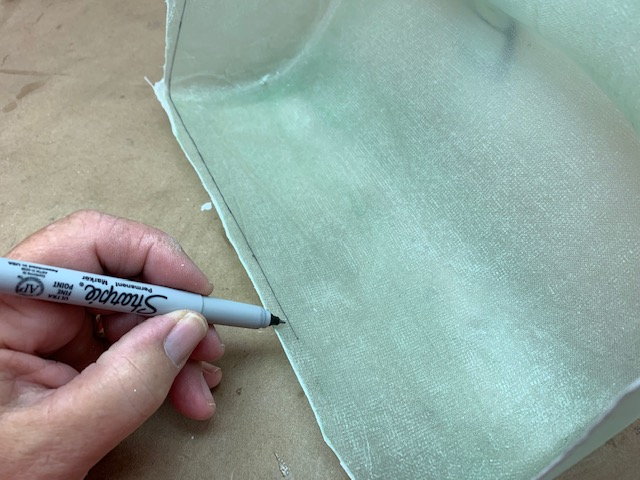
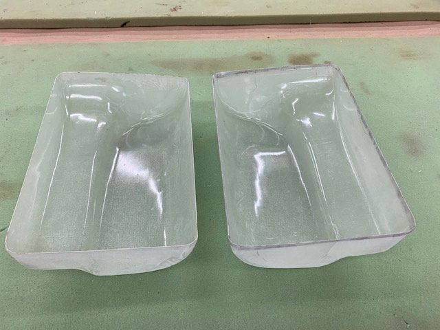
Tank half after trimming and sanding the edges
Seemed to be a usable part
Plug ready to sand and re-wax for next half.
Had another pop up weekend trip so it will be next week before I can lay up the next part. More adventure to come...
06-20-2020, 05:19 PM
#611
Thread Starter
My Feedback: (20)
Got back from trip early so second half tank layup prep completed
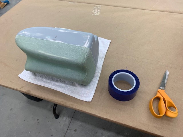
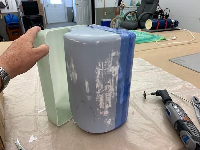
The small nicks on the plug were wet sanded with 1200 grit paper. Then the 1st tank half placed back on plug
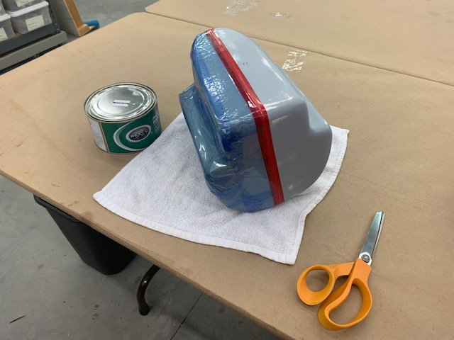
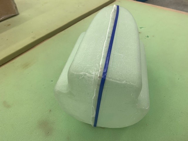
Vinyl tape applied over center joint. The flash tape would not stretch over compound curves and left wrinkles which would lock the new part on the plug. I used vinyl tape that stretched over the joint and stayed smooth. Then the flash tape was used t cover the first half part.

Clear packing tape used to secure plug into the box for stability as before
4 coats of Partall past wax rubbed on plug and buffed off
One coat of PVA brushed on plug. Next is the epoxy and glass layups.
The small nicks on the plug were wet sanded with 1200 grit paper. Then the 1st tank half placed back on plug
Vinyl tape applied over center joint. The flash tape would not stretch over compound curves and left wrinkles which would lock the new part on the plug. I used vinyl tape that stretched over the joint and stayed smooth. Then the flash tape was used t cover the first half part.
Clear packing tape used to secure plug into the box for stability as before
4 coats of Partall past wax rubbed on plug and buffed off
One coat of PVA brushed on plug. Next is the epoxy and glass layups.
Last edited by Viper1GJ; 06-20-2020 at 05:22 PM.
The following users liked this post:
bonefishfool (06-20-2020)
06-22-2020, 05:37 PM
#612
Thread Starter
My Feedback: (20)
Removed 2nd half layup from vacuum bag
Breather cloth came off easy because of the blue perforated release film underneath
Release film peeled off easy

Peel ply was saturated so it took a little more effort to get it off. Pliers help grip it to get started
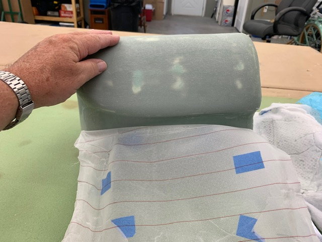
Peel ply pulled off the flat parts pretty easy

Now ready for the fun part. I'm confident it will come off, just not sure how hard it will be. Will have to wait till tomorrow due to yard and other chores.
Breather cloth came off easy because of the blue perforated release film underneath
Release film peeled off easy
Peel ply was saturated so it took a little more effort to get it off. Pliers help grip it to get started
Peel ply pulled off the flat parts pretty easy
Now ready for the fun part. I'm confident it will come off, just not sure how hard it will be. Will have to wait till tomorrow due to yard and other chores.
06-23-2020, 03:10 PM
#613
Thread Starter
My Feedback: (20)
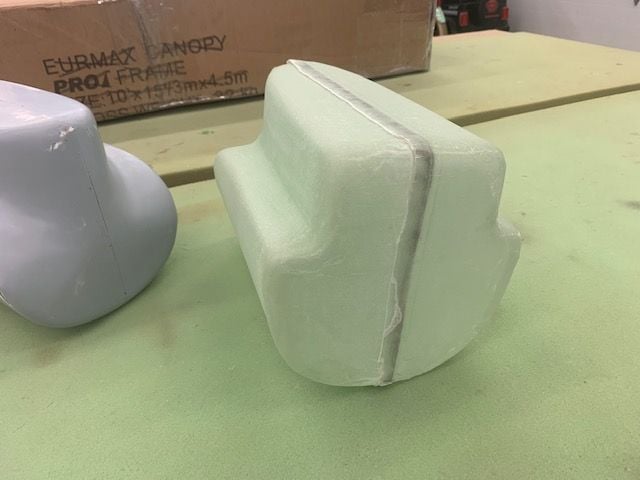
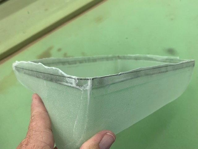
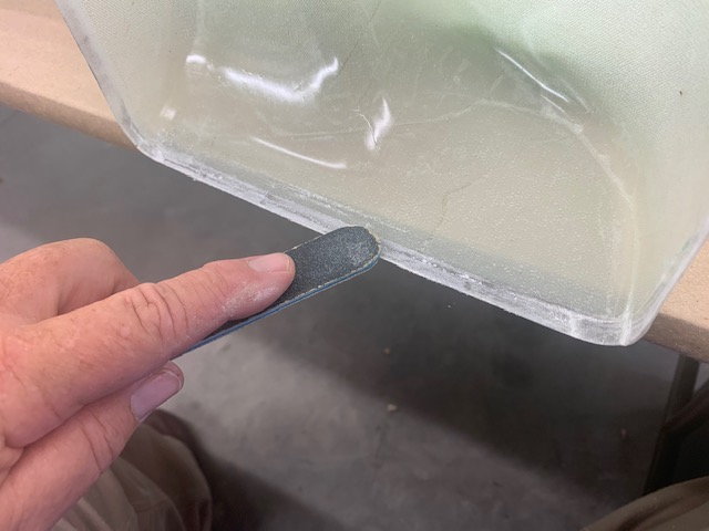
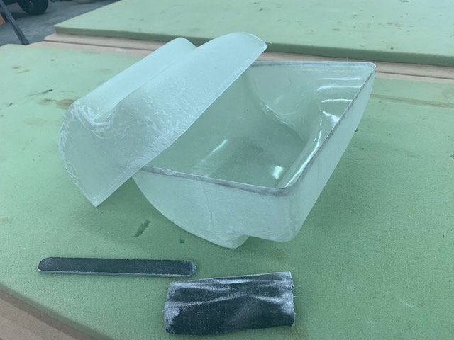
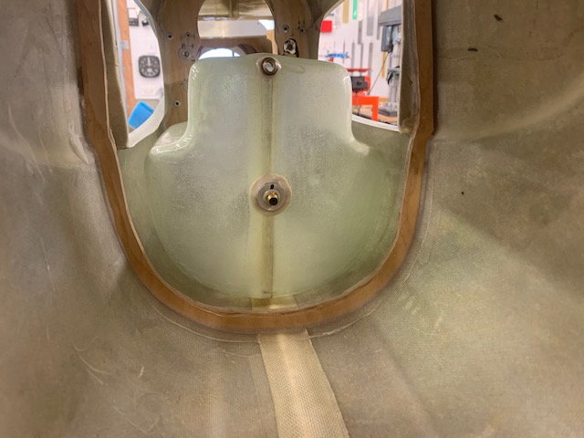
Removing 2nd half of tank from mold
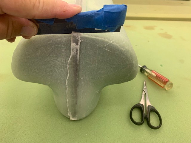
Well the fun began. I could see the part separate from the mold surface using a putty knife to slide under the layup and it popped up using compressed air. But it would not slide off the corners. After about 30 min of trimming, pulling, prying, and compressed air blowing with no luck getting it off, I decided to make a thin relief cut on the top and bottom corners.
I used a razor saw to make a thin cut.
That did the trick and after a few minutes I was finally able to separate the part from the mold
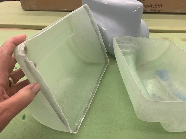
It looked like a usable part
First test fit was good
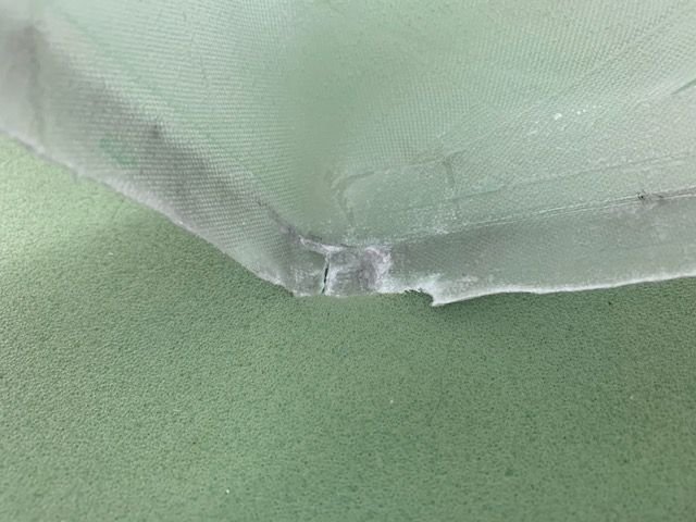
The cuts did not go past the seam so it should be an easy fix when joining the tank halves.
1/4" tape applied to the lap joint to assist in marking the trim cut line.
Trim line marked
Parts trimmed, sanded and PVA washed out and dried
I had some epoxy channels form under the peel ply where I did not make sure it was flat under the breather cloth. I sanded them down a little. Lesson learned. I plan to give the outside surface two coats of epoxy after bonding and glassing the center joint. That will help ensure no pin holes and improve outside appearance.
I learned a lot doing a new composite process that I never tried before. It was a lot of work but at least I have a usable tank. The big lesson learned was design of the plug must ensure proper draft angles to allow the part to pop off the plug. I have a new respect for you guys building entire airplanes this way.
Well the fun began. I could see the part separate from the mold surface using a putty knife to slide under the layup and it popped up using compressed air. But it would not slide off the corners. After about 30 min of trimming, pulling, prying, and compressed air blowing with no luck getting it off, I decided to make a thin relief cut on the top and bottom corners.
I used a razor saw to make a thin cut.
That did the trick and after a few minutes I was finally able to separate the part from the mold
It looked like a usable part
First test fit was good
The cuts did not go past the seam so it should be an easy fix when joining the tank halves.
1/4" tape applied to the lap joint to assist in marking the trim cut line.
Trim line marked
Parts trimmed, sanded and PVA washed out and dried
I had some epoxy channels form under the peel ply where I did not make sure it was flat under the breather cloth. I sanded them down a little. Lesson learned. I plan to give the outside surface two coats of epoxy after bonding and glassing the center joint. That will help ensure no pin holes and improve outside appearance.
I learned a lot doing a new composite process that I never tried before. It was a lot of work but at least I have a usable tank. The big lesson learned was design of the plug must ensure proper draft angles to allow the part to pop off the plug. I have a new respect for you guys building entire airplanes this way.
Last edited by Viper1GJ; 06-23-2020 at 03:12 PM.
 06-23-2020, 03:49 PM
#615
Thread Starter
My Feedback: (20)
Thanks Thomas, I'll take a compliment from you any day. Thanks for you advice and ideas. I guess the proper way would have been to make a female mold but I did not want to do that much work for a one off part, plus I've never done it before. I think using CAD and 3D printing is the way to go making the tools for sure.
Gary
Gary
06-23-2020, 08:56 PM
#616
Thanks Thomas, I'll take a compliment from you any day. Thanks for you advice and ideas. I guess the proper way would have been to make a female mold but I did not want to do that much work for a one off part, plus I've never done it before. I think using CAD and 3D printing is the way to go making the tools for sure.
Gary
Gary
i agree completely! With some cad programs, you can do draft analysis and it�ll show you exactly where the problems. Your tank while fairly simple does have some complex area�s as you have found and you did a good job at working with what you had.
07-22-2020, 05:06 PM
#617
Thread Starter
My Feedback: (20)
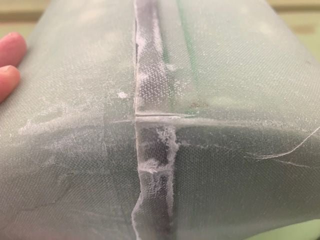
Gluing tank halves together.
I finally got back to the F-105 project after about a month off for family vacation and several other projects none of which were airplanes.
First I scuffed the inside of the lip where the tank halves will join with a sanding stick and sandpaper
Next I scuffed the outside of the other tank half
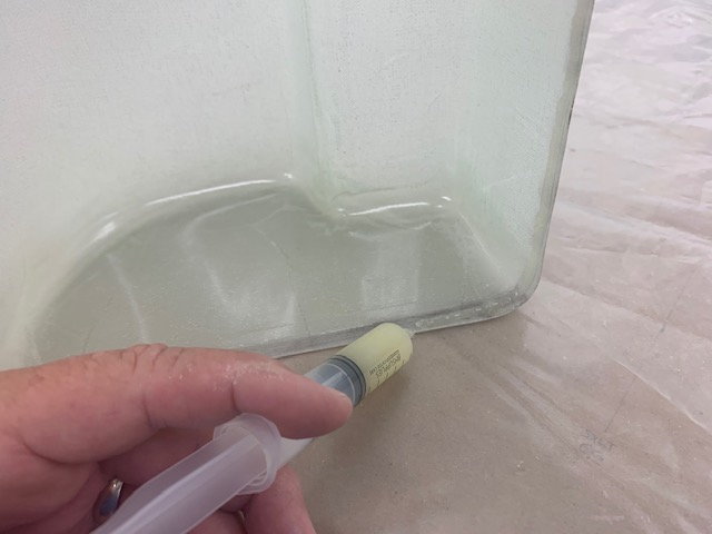
Next I mixed up some Six10 epoxy in a syringe and applied a bead to the inside of the joint lip

I used a dab of 5 min epoxy over the Six10 in the corners to get a fast tack so the joint would not shift during the cure and later handling making the fillets.
After the Six10 went green, I mixed another batch of and forced it into the joint line to get a solid bond across the full surface of the overlap. Then I spread the remaining epoxy over the joint line and scraped it off with the putty knife to form a fillet from the joint line to the surface all around the tank. I will sand this smooth and apply fiberglass over the joint line later.
I finally got back to the F-105 project after about a month off for family vacation and several other projects none of which were airplanes.
First I scuffed the inside of the lip where the tank halves will join with a sanding stick and sandpaper
Next I scuffed the outside of the other tank half
Next I mixed up some Six10 epoxy in a syringe and applied a bead to the inside of the joint lip
I used a dab of 5 min epoxy over the Six10 in the corners to get a fast tack so the joint would not shift during the cure and later handling making the fillets.
After the Six10 went green, I mixed another batch of and forced it into the joint line to get a solid bond across the full surface of the overlap. Then I spread the remaining epoxy over the joint line and scraped it off with the putty knife to form a fillet from the joint line to the surface all around the tank. I will sand this smooth and apply fiberglass over the joint line later.
Last edited by Viper1GJ; 07-22-2020 at 05:09 PM.
The following 2 users liked this post by Viper1GJ:
bonefishfool (07-22-2020),
[email protected] (07-22-2020)
07-23-2020, 04:08 PM
#618
Thread Starter
My Feedback: (20)
Elevator servo mounts
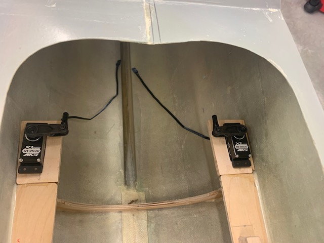
I got the elevator servo mounts tacked in for dry fits today. Using MKS HV9930 servos.

View from the rear. The servo mounts will have some vertical braces for stiffness and strength when done.
Done for the week, going for a 3 day jet flying weekend. If I dont sweat away from the heat I'll get back to it next week.
I got the elevator servo mounts tacked in for dry fits today. Using MKS HV9930 servos.
View from the rear. The servo mounts will have some vertical braces for stiffness and strength when done.
Done for the week, going for a 3 day jet flying weekend. If I dont sweat away from the heat I'll get back to it next week.
07-31-2020, 05:15 PM
#619
Thread Starter
My Feedback: (20)
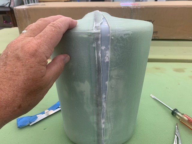
Glass over tank seam
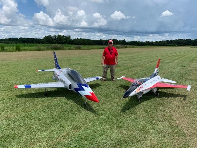
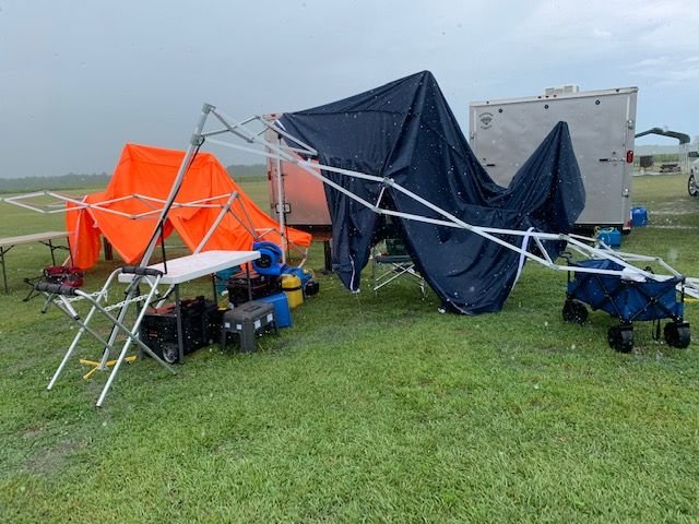
The 3 day jet together went well. The big F-16 and Havoc flew well all weekend. The only casualty was my brand new tent. It got destroyed in a pop up thunder storm that formed right above us. It started with light rain for about 10 min and then dumped heavy rain with winds that were measured at 44 mph before the wind sensor got blown away. I tried to hold the tent down but it lifted me off the ground before it was pulled out of my hands. Repair parts ordered.
I sanded the outside of the tank to remove all the flaws left from my sloppy lay ups. There were several epoxy runners from wrinkled peel ply, wrinkled glass marks with threads and the seam itself. After sanding I was going to apply a 2" glass tape around the seam area but instead I decided to cover the entire tank with 2 more layers of 3 oz satin weave glass. It really improved the stiffness of the sides and the overall appearance of the outside of the tank. I will give the edges of the last layers a light sanding and then one more coat of epoxy to make sure everything is sealed real good. Then the fittings and tank mounts will be added.
Last edited by Viper1GJ; 07-31-2020 at 05:26 PM.
The following users liked this post:
f106jax (08-02-2020)
08-02-2020, 04:07 PM
#620
Thread Starter
My Feedback: (20)
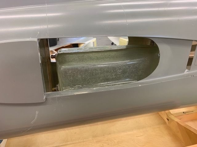
Tank fittings installed
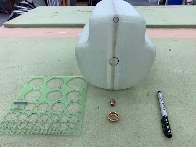
Pretty straight forward. Marked. I'm using 1/4" ID fuel fittings from Gary at Jet Tech.
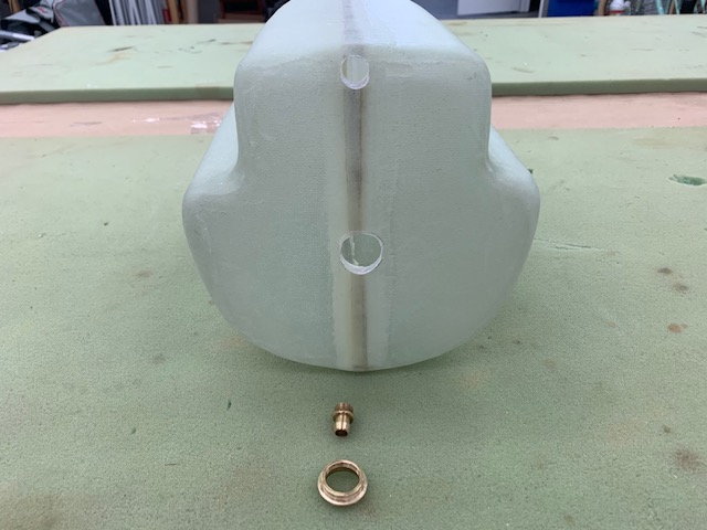
Holes cut and fittings dry fit
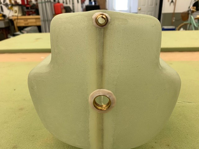
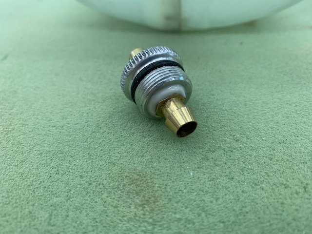
FIttings installed with hysol. The last coat of resin will go on after the hysol cures.
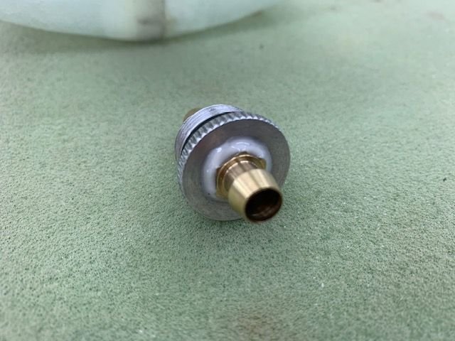
Hysol on nipple fittings screw in stopper.
The other side.
Pretty straight forward. Marked. I'm using 1/4" ID fuel fittings from Gary at Jet Tech.
Holes cut and fittings dry fit
FIttings installed with hysol. The last coat of resin will go on after the hysol cures.
Hysol on nipple fittings screw in stopper.
The other side.
08-12-2020, 04:20 PM
#621
Thread Starter
My Feedback: (20)
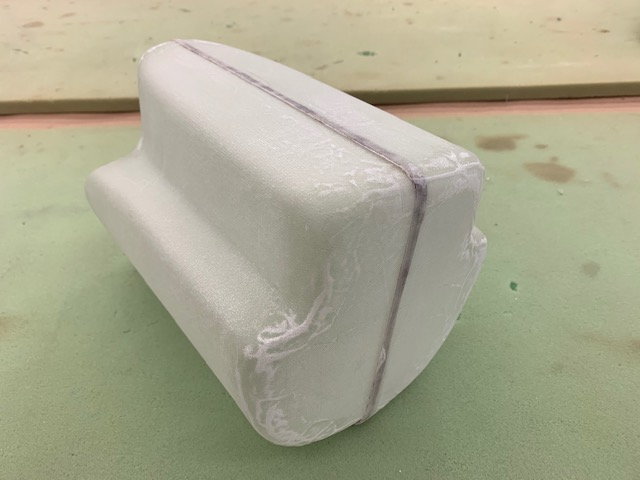
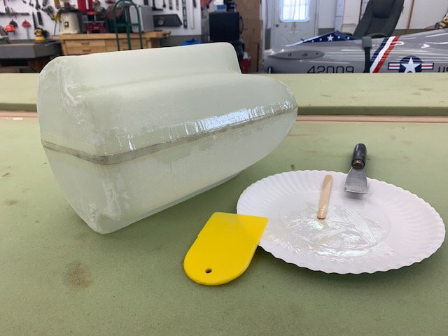
Tank completed
Tank coated with final coat of epoxy resin to seal any pin holes
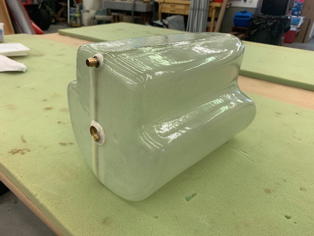
Done with making tank
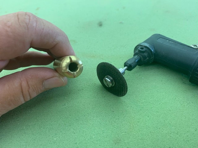
Anti suction slots cut on bottom of brass clunk
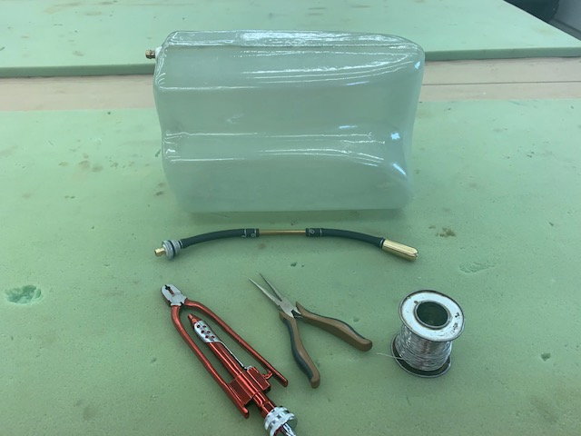
Tank clunk line fabricated with 1/4" ID brass tube and 1/4" ID Viton tubing and safety wired
Shake tests good!
Tank coated with final coat of epoxy resin to seal any pin holes
Done with making tank
Anti suction slots cut on bottom of brass clunk
Tank clunk line fabricated with 1/4" ID brass tube and 1/4" ID Viton tubing and safety wired
Shake tests good!
08-12-2020, 04:56 PM
#622
Thread Starter
My Feedback: (20)
Making tank mount
I spent a long time trying to figure out how to mount the tank. Requirements were to be easily removable, see the quantity of fuel remaining from the front and rear, not shift inside fuse, not easy to break, and easy to make. OK, now what?
After an hour of thinking I elected to use a 1.5" wide Velcro One Wrap strap over the top center of the tank to hold it down to the bottom of the fuse. The rear former will keep it from moving back, a small block installed in front on the floor will keep it from moving forward, the strap will hold it down and make it easy to take out over the forward block. Also the view of both ends will not be blocked by brackets or mounts that could break off or crack the tank after a hard knock.
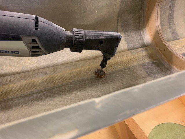
First step was to smooth out the bottom of the fuse floor below the tank. I ground the edges of the center seam strip and sanded it smooth.
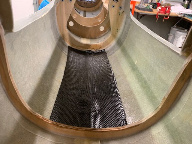
To stiffen and strengthen the fuse floor I laid in a strip of carbon fiber between the fuse formers.

A carbon fiber tank cradle was formed using the bottom of the tank as a mold. First a piece of plastic is taped to the bottom of the tank. The carbon pieces are wetted out on a piece of plastic and excess resin scraped off. Then they are stacked on the bottom of the tank. This makes 3 layers of carbon cloth with the middle layer on a 45 degree bias angle. Then another piece of plastic is placed on top and smoothed out. Then the whole sandwich is taped down on the tank with clear packing tape to cure. Edges will be trimmed after the cure.
The bracket will be glued to the tank floor with space underneath to slide the Velcro strap under and then over the top of the tank. I learned this technique from Paul Appelbaum with his Freewing F-4 foamy conversion. We will see how it works with the bigger tank here.
I spent a long time trying to figure out how to mount the tank. Requirements were to be easily removable, see the quantity of fuel remaining from the front and rear, not shift inside fuse, not easy to break, and easy to make. OK, now what?
After an hour of thinking I elected to use a 1.5" wide Velcro One Wrap strap over the top center of the tank to hold it down to the bottom of the fuse. The rear former will keep it from moving back, a small block installed in front on the floor will keep it from moving forward, the strap will hold it down and make it easy to take out over the forward block. Also the view of both ends will not be blocked by brackets or mounts that could break off or crack the tank after a hard knock.
First step was to smooth out the bottom of the fuse floor below the tank. I ground the edges of the center seam strip and sanded it smooth.
To stiffen and strengthen the fuse floor I laid in a strip of carbon fiber between the fuse formers.
A carbon fiber tank cradle was formed using the bottom of the tank as a mold. First a piece of plastic is taped to the bottom of the tank. The carbon pieces are wetted out on a piece of plastic and excess resin scraped off. Then they are stacked on the bottom of the tank. This makes 3 layers of carbon cloth with the middle layer on a 45 degree bias angle. Then another piece of plastic is placed on top and smoothed out. Then the whole sandwich is taped down on the tank with clear packing tape to cure. Edges will be trimmed after the cure.
The bracket will be glued to the tank floor with space underneath to slide the Velcro strap under and then over the top of the tank. I learned this technique from Paul Appelbaum with his Freewing F-4 foamy conversion. We will see how it works with the bigger tank here.
08-12-2020, 05:17 PM
#623
Thread Starter
My Feedback: (20)
Servos mounted
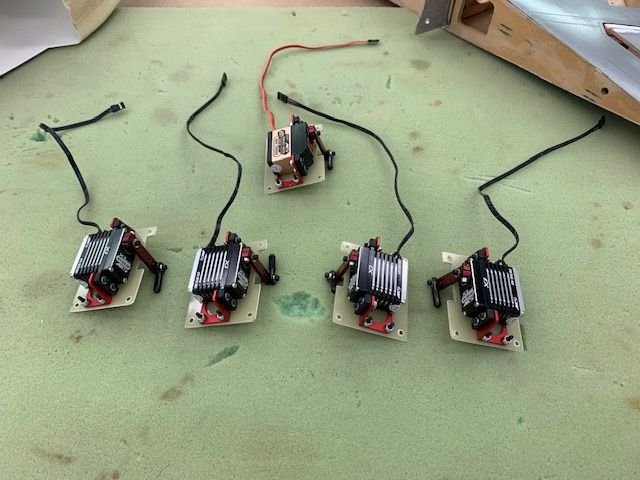
Servos are mounted to the servo plates. MKS HV9930 on all but rudder, MKS 777A+ for rudder.
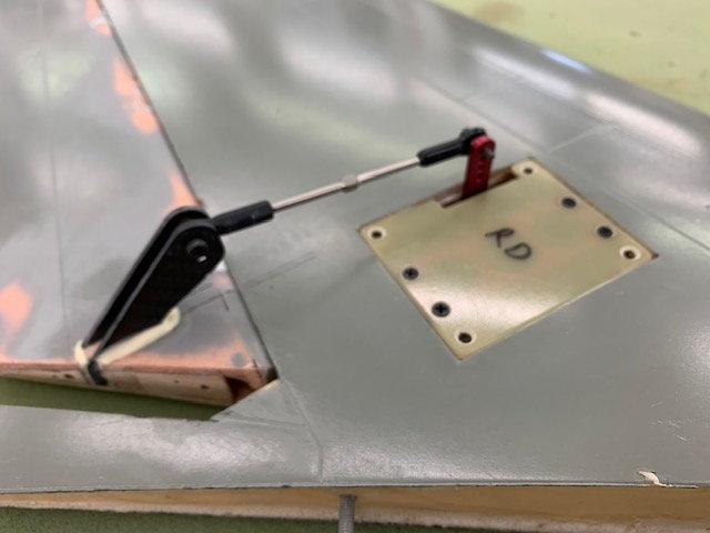
Rudder pushrod installed and adjusted. This is the only pushrod I had on hand that would fit so I'm waiting for the aileron and flap rods to arrive.

Holes cut for rudder servo wire to get from inside the vertical fin to inside the fuse

Elevator servos mounted to fuse mounts. I still have to epoxy the servo mounts to the fuse.
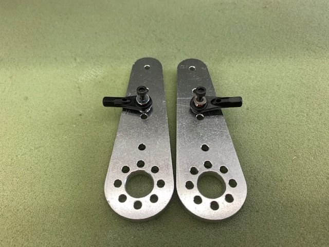
Stab control horns drilled for 3mm ball links. Still waiting on 8mm carbon fiber push rods to arrive.
Using a 1.18" (30mm) servo arm and a 1.75" stab horn gives me a minimum of 481 in/oz torque required using the AMA LMA calculations. The MKS HV9930 provides 538 in/oz at 7.4v. This meets and exceeds the AMA LMA requirements.
Servos are mounted to the servo plates. MKS HV9930 on all but rudder, MKS 777A+ for rudder.
Rudder pushrod installed and adjusted. This is the only pushrod I had on hand that would fit so I'm waiting for the aileron and flap rods to arrive.
Holes cut for rudder servo wire to get from inside the vertical fin to inside the fuse
Elevator servos mounted to fuse mounts. I still have to epoxy the servo mounts to the fuse.
Stab control horns drilled for 3mm ball links. Still waiting on 8mm carbon fiber push rods to arrive.
Using a 1.18" (30mm) servo arm and a 1.75" stab horn gives me a minimum of 481 in/oz torque required using the AMA LMA calculations. The MKS HV9930 provides 538 in/oz at 7.4v. This meets and exceeds the AMA LMA requirements.