


1/6 F-105 Build Thread
 06-02-2020, 07:29 AM
#576
After making several tanks..............a nice trick is to install some brass tubing ...1/4 " or so.....on the (projected ) trouble corners or other spots on the mold . Then you can use air pressure to push on those corner areas. Sometimes it helps pop the part loose. A tiny piece of tape over the hole keeps the epoxy out.
 06-02-2020, 04:51 PM
#577

Thread Starter
My Feedback: (20)
That sounds like a great idea if I have to make a female mold. I was not planning to to that. I was planning to use the plug as a male mold and drape the glass over the outside of it to make left and right halves. If this does not work out I can always make a female mold and try again.
Thanks, Gary
Thanks, Gary
06-03-2020, 04:04 PM
#579
Thread Starter
My Feedback: (20)
That's exactly what I did on my first homemade tanks. Worked ok but if for some reason it fails or I finally need to make a female mold it would mess up my plug. Hoping my plan for two sides will work just like the ones Paul makes for the foamie turbine conversions, just a larger size. If not I could use the plug to make a mold. I've never done that before either. The photos of my first try are here in post #461-#463: Skymaster 1/5 Scale F16 Build Thread #461-#463 Thanks for the tips.
Things got slowed down this week. Went to dermatology doc to get a skin cancer spot on top of my head removed. Top of my head feels like I'm hanging from a giant claw and hurts alot so I did not get any tank work done the last two days. Mostly did some design work on a drag chute deploy and release system then quit for the day. More to come when feeling better. Also waiting for some more glass and release film to come in.
Gary
06-03-2020, 09:15 PM
#580
Join Date: Jul 2007
Location: Karachi, PAKISTAN
Posts: 13
Likes: 0
Received 0 Likes
on
0 Posts
06-04-2020, 05:58 AM
#581

That's exactly what I did on my first homemade tanks. Worked ok but if for some reason it fails or I finally need to make a female mold it would mess up my plug. Hoping my plan for two sides will work just like the ones Paul makes for the foamie turbine conversions, just a larger size. If not I could use the plug to make a mold. I've never done that before either. The photos of my first try are here in post #461-#463: Skymaster 1/5 Scale F16 Build Thread #461-#463 Thanks for the tips.
06-05-2020, 04:07 AM
#582
That's exactly what I did on my first homemade tanks. Worked ok but if for some reason it fails or I finally need to make a female mold it would mess up my plug. Hoping my plan for two sides will work just like the ones Paul makes for the foamie turbine conversions, just a larger size. If not I could use the plug to make a mold. I've never done that before either. The photos of my first try are here in post #461-#463: Skymaster 1/5 Scale F16 Build Thread #461-#463 Thanks for the tips.
Things got slowed down this week. Went to dermatology doc to get a skin cancer spot on top of my head removed. Top of my head feels like I'm hanging from a giant claw and hurts alot so I did not get any tank work done the last two days. Mostly did some design work on a drag chute deploy and release system then quit for the day. More to come when feeling better. Also waiting for some more glass and release film to come in.
Gary

 06-05-2020, 02:09 PM
#584

Gary,
one think you can do that i have done that works well. Layup a tank half that goes just past the centerline of the tank and leave it to cure. Once it cures, remove the tank half, trimmed the excess glass off and put the half back onto the tank.
then using some Flash Breaker tape, put a strip around the perimeter of the tank shell half and onto the tank plug so that the tape is centered over the joint. Then make a 2-3� wide area of the tank shell previously layed up covered in the flash breaker tape. Then you can layup the other half of the tank and have the glass of this layup overlap onto the previous tank half ontop of the flash breaker tape. This makes up an automatic flange on one tank shell half to bond the two pieces together.
06-05-2020, 04:30 PM
#585
Thread Starter
My Feedback: (20)
Thomas, this is exactly the process I want to use. This is how Paul A. makes his foamie conversion tanks. He sent me photos of his process and I was trying to follow it. Thats why I'm trying to make the plug smooth with proper draft angles so I can pull the tank half off with out damage to the plug or part.
I dont know what "flash breaker tape" is. I was going to try to use some electrical tape, automotive fine line masking tape, or just clear packing tape. Does the flash tape have any stretch to cover the small gap from the first layup to the plug on the second layup?
Also the reason I vacuumed bagged the plug layup and planned to bag the tank half layup is to make sure the fabric will stay down on the edges. My first attempt at tanks I had a hard time getting the fabric to stay flat on the edges especially over the curved corners. I used 3.1 oz satin weave 120 style on this plug and it was softer and easier to keep down. I was concerned the 6 oz plain weave edges would not stay down.
Thanks for the help,
Gary
06-06-2020, 04:46 AM
#586
Thomas, this is exactly the process I want to use. This is how Paul A. makes his foamie conversion tanks. He sent me photos of his process and I was trying to follow it. Thats why I'm trying to make the plug smooth with proper draft angles so I can pull the tank half off with out damage to the plug or part.
I dont know what "flash breaker tape" is. I was going to try to use some electrical tape, automotive fine line masking tape, or just clear packing tape. Does the flash tape have any stretch to cover the small gap from the first layup to the plug on the second layup?
Also the reason I vacuumed bagged the plug layup and planned to bag the tank half layup is to make sure the fabric will stay down on the edges. My first attempt at tanks I had a hard time getting the fabric to stay flat on the edges especially over the curved corners. I used 3.1 oz satin weave 120 style on this plug and it was softer and easier to keep down. I was concerned the 6 oz plain weave edges would not stay down.
Thanks for the help,
Gary
I dont know what "flash breaker tape" is. I was going to try to use some electrical tape, automotive fine line masking tape, or just clear packing tape. Does the flash tape have any stretch to cover the small gap from the first layup to the plug on the second layup?
Also the reason I vacuumed bagged the plug layup and planned to bag the tank half layup is to make sure the fabric will stay down on the edges. My first attempt at tanks I had a hard time getting the fabric to stay flat on the edges especially over the curved corners. I used 3.1 oz satin weave 120 style on this plug and it was softer and easier to keep down. I was concerned the 6 oz plain weave edges would not stay down.
Thanks for the help,
Gary
Gary,
the 3733 style 6oz is very easy to work with. Its a slightly looser weave, but it conforms over curves extremely well.
one thing you can try to help keep things down, is to apply the first layer of glass and then leave it to cure until it has gone �green�, basically it�ll be sticky to the point you can transfer your fingerprint to the resin, but not have the resin transfer to your finger.
the flash breaker tape is a transparent green looking packing tape, but its much more durable. Packing tape would honestly work just as well. The flash breaker tape doesnt have much stretch, if any.
06-06-2020, 03:04 PM
#587
Thread Starter
My Feedback: (20)
Thomas,
Thanks, got some 3733 and flash tape ordered today. Will not get much done next week due to family vacation. Hopefully stuff will arrive next week and be ready to continue the following week.
Thanks again,
Gary
Thanks, got some 3733 and flash tape ordered today. Will not get much done next week due to family vacation. Hopefully stuff will arrive next week and be ready to continue the following week.
Thanks again,
Gary
06-08-2020, 05:17 PM
#588
Thread Starter
My Feedback: (20)
Drag Chute
The next steps on the tank plug required sanding and since the doc said don't do any work for a week sanding seemed like work. So I just sat in the chair for about 3 days thinking up how to stuff a drag chute in the back of the fuse. I finally came up with a plan which got changed about a dozen times and is still a work in progress but here is where it stands now.
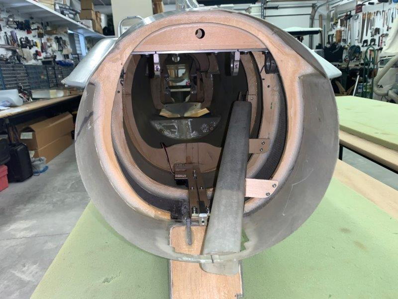
I planned on using a Skymaster F-4 drag chute system and adapting it to the space available. It uses a long air ram to eject the chute from a fiberglass tube. I also had to think up a way to attach and jettison the chute. My plan for that was to use a glider tow plane release. After thinking up a plan that would clear the pipe, go through the door, allow hooking up and release, clear the hinges and open the door I started out by attaching the door hinges. I copied the door hinges used by one of the photos from Joe Grice.
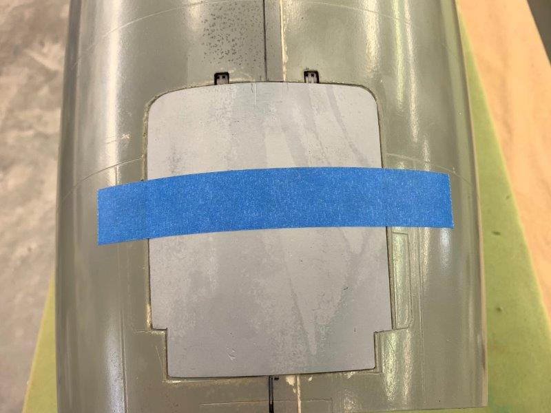
Notches cut forward of the door hinge line to allow the door to clear the curve on the top of the fuse when open, similar to offset hinges. Door taped in place and hinges tack glued in place with CA to test.
Door opens about 60 degrees
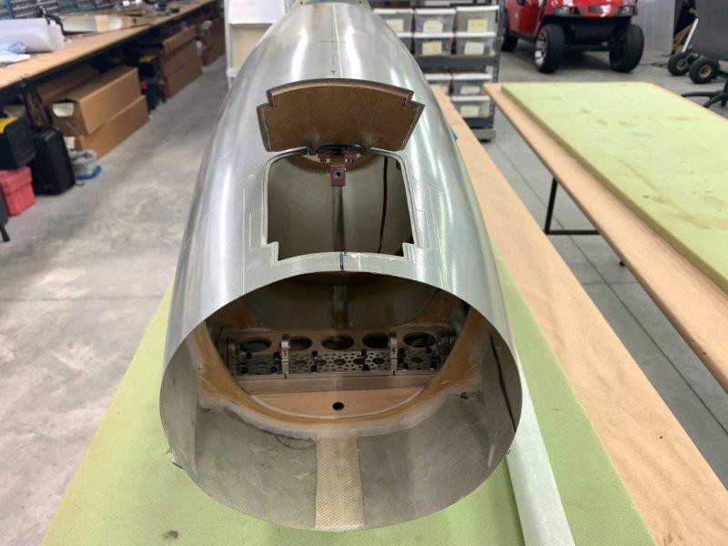
Looking inside from rear. Fuse is upside down here. HInges tack glued in place

From side. Tape holding door open
The next steps on the tank plug required sanding and since the doc said don't do any work for a week sanding seemed like work. So I just sat in the chair for about 3 days thinking up how to stuff a drag chute in the back of the fuse. I finally came up with a plan which got changed about a dozen times and is still a work in progress but here is where it stands now.
I planned on using a Skymaster F-4 drag chute system and adapting it to the space available. It uses a long air ram to eject the chute from a fiberglass tube. I also had to think up a way to attach and jettison the chute. My plan for that was to use a glider tow plane release. After thinking up a plan that would clear the pipe, go through the door, allow hooking up and release, clear the hinges and open the door I started out by attaching the door hinges. I copied the door hinges used by one of the photos from Joe Grice.
Notches cut forward of the door hinge line to allow the door to clear the curve on the top of the fuse when open, similar to offset hinges. Door taped in place and hinges tack glued in place with CA to test.
Door opens about 60 degrees
Looking inside from rear. Fuse is upside down here. HInges tack glued in place
From side. Tape holding door open
06-08-2020, 05:34 PM
#589
Thread Starter
My Feedback: (20)
Chute release system
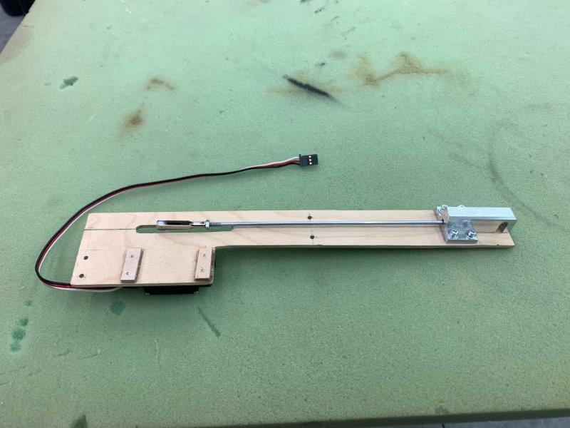
After a lot tinkering and dry fitting I came up with this system using the glider tow release and servo to attach and jettison the chute. This part had to be removable for service but securely attached to the airframe.
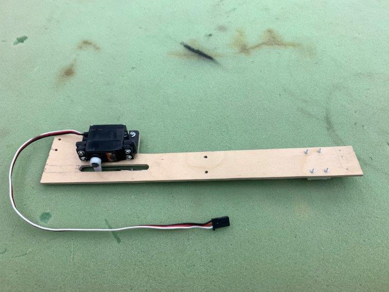
Servo on other side.

Dry fit between hinges

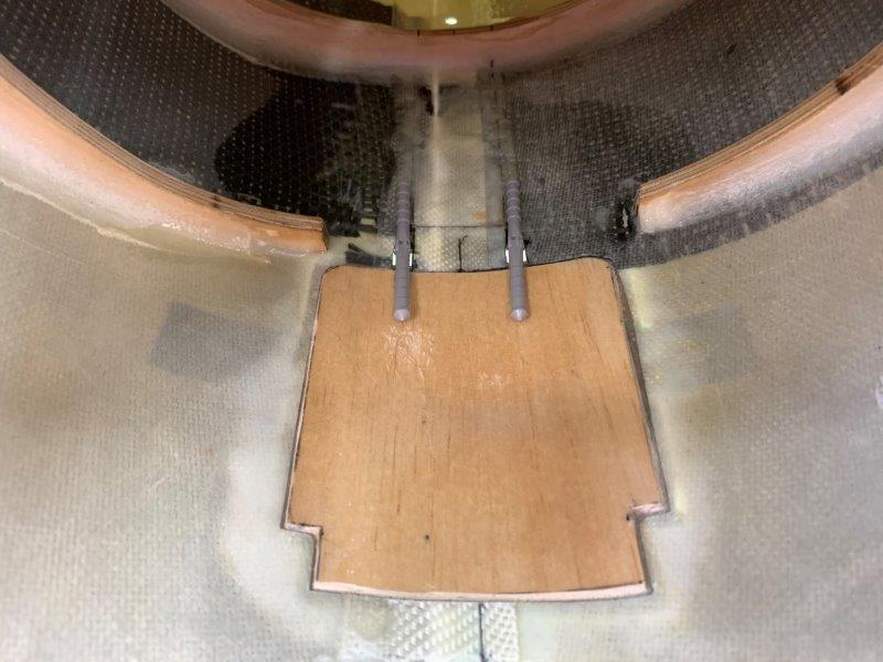
1/4" ply plate tapered to fit just below the aluminum release bracket.

Block and former brackets glued in on fuse
Chute release system screwed in place. This is just below the vertical fin inside top of fuse.
After a lot tinkering and dry fitting I came up with this system using the glider tow release and servo to attach and jettison the chute. This part had to be removable for service but securely attached to the airframe.
Servo on other side.
Dry fit between hinges
1/4" ply plate tapered to fit just below the aluminum release bracket.
Block and former brackets glued in on fuse
Chute release system screwed in place. This is just below the vertical fin inside top of fuse.
06-08-2020, 05:46 PM
#590
Thread Starter
My Feedback: (20)
Deployment tube
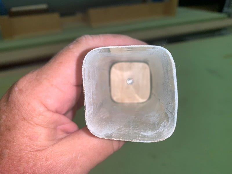
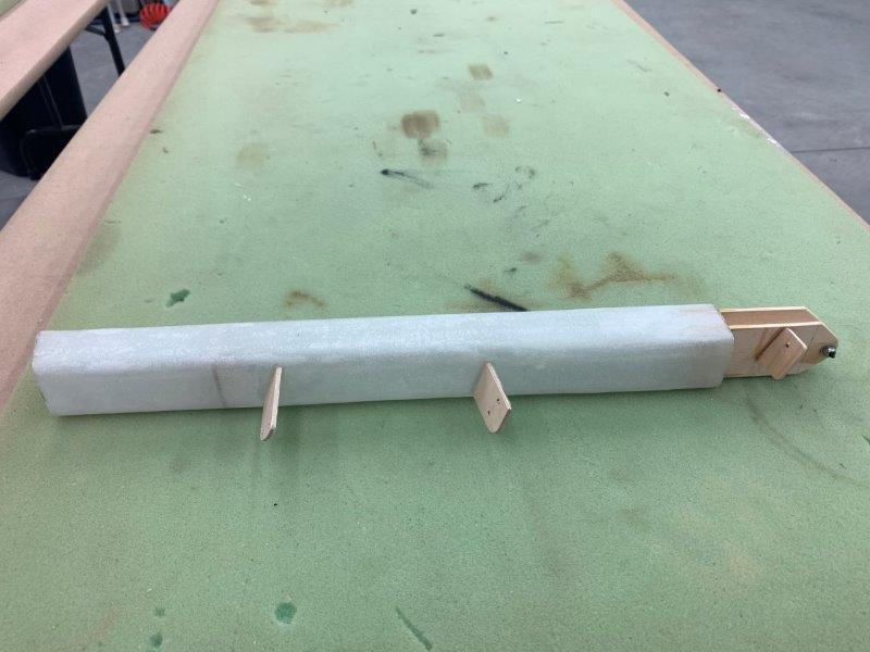
I needed a longer fiberglass tube than came with the chute system. I also need a square shaped tube instead of a round one to fit through the door. I used the lost foam method to make a quick mold.

Pink fan fold foam cut to strips to make a 1.5 x 1.5" tube
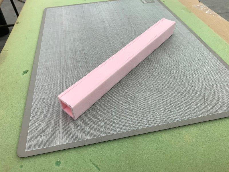
Parts glued together
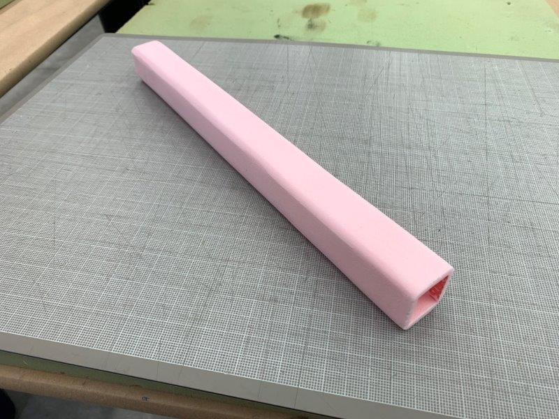
Corners rounded
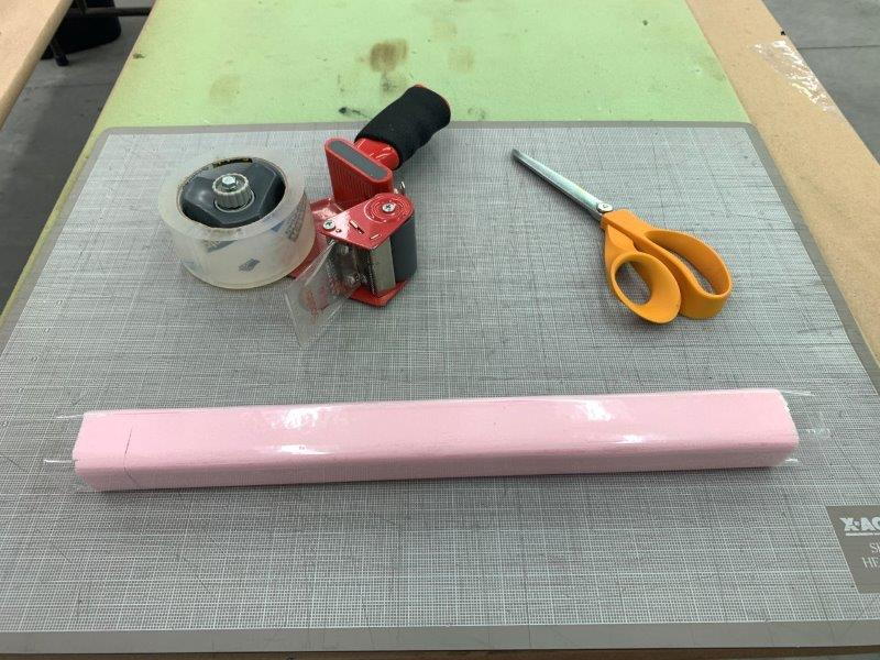
Covered with clear packing tape and waxed with J&J paste wax
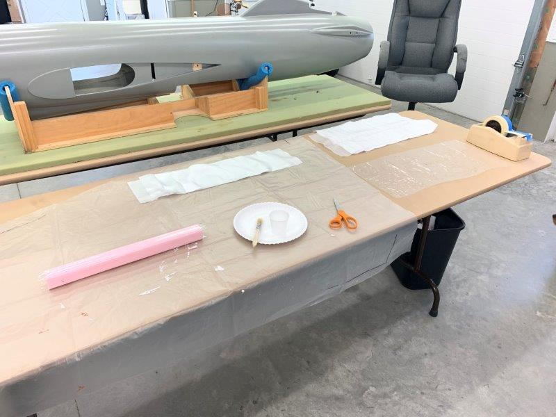
Fiberglass and peel ply cut and ready to lay up.
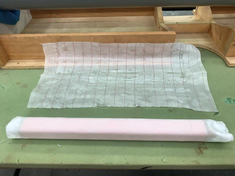
Layup cured the next day and peel ply removed
Dry glass cut off the ends and ready for part removal

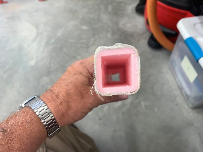
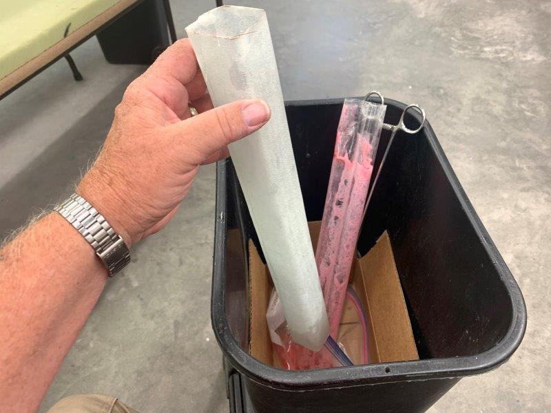
Laquer thinner used to melt out the foam. Baggie and box caught thinner in the trash can
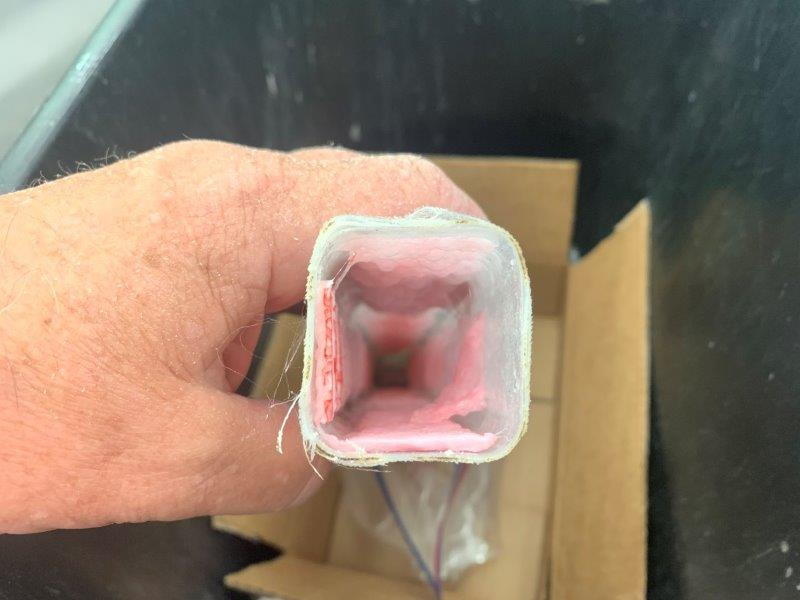
Foam melted out with just a few ounces of thinner

Packing tape removed from inside the new tube
Done ready for trimming
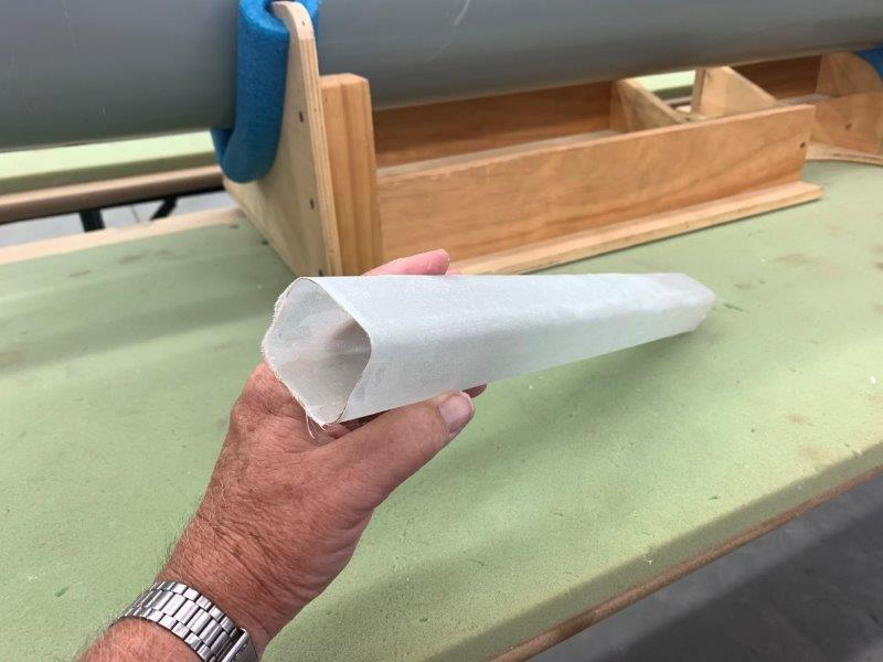
Finished part ready for fitting
I needed a longer fiberglass tube than came with the chute system. I also need a square shaped tube instead of a round one to fit through the door. I used the lost foam method to make a quick mold.
Pink fan fold foam cut to strips to make a 1.5 x 1.5" tube
Parts glued together
Corners rounded
Covered with clear packing tape and waxed with J&J paste wax
Fiberglass and peel ply cut and ready to lay up.
Layup cured the next day and peel ply removed
Dry glass cut off the ends and ready for part removal
Laquer thinner used to melt out the foam. Baggie and box caught thinner in the trash can
Foam melted out with just a few ounces of thinner
Packing tape removed from inside the new tube
Done ready for trimming
Finished part ready for fitting
06-08-2020, 06:03 PM
#591
Thread Starter
My Feedback: (20)
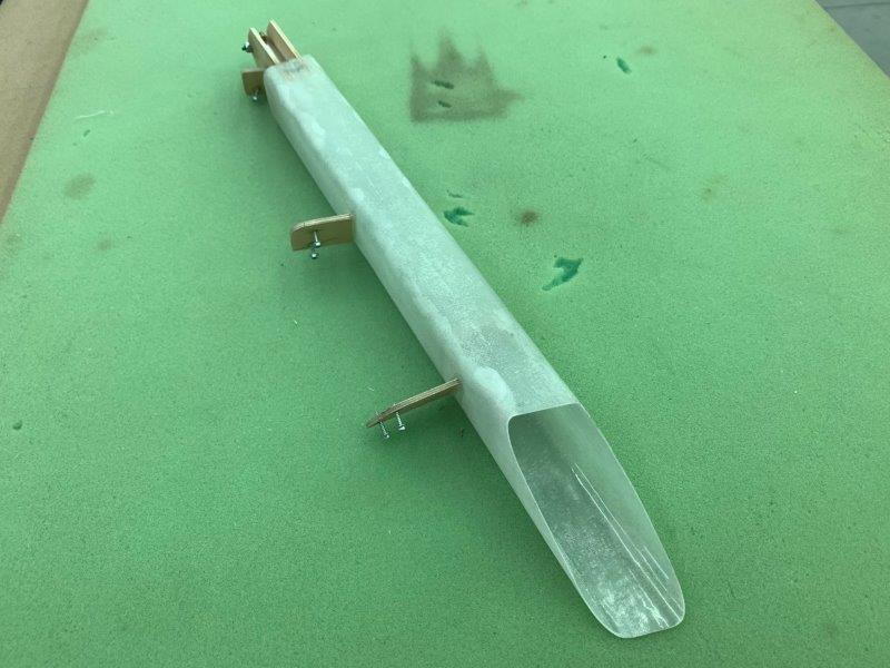
Fabricating the deployment tube
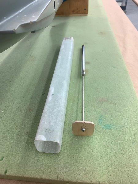
Air ram fitted with push plate to shove the chute out the back
Deployment ram push plate slides back and forth inside the tube. The square tube actually has a little more volume to hold the folded chute than the round one had.
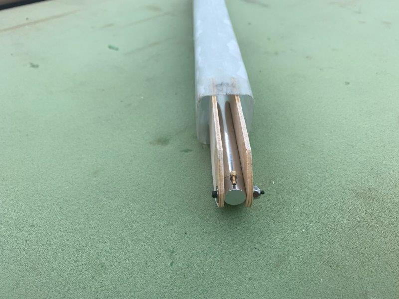
After about 2 days fussing with the length of the tube and stroke of the ram I figured out I needed to extend the ram out the front of the tube about 2.5 inches to keep the ram plate from hanging up on the door after deploying the chute. So I made some longer ram mounts and glued inside the tube.
Front of the deployment tube
After trying all possible angles and positions this one seems to work the best. When right side up the tube will be on the upper left side of the fuse. It will clears the pipe, (it is actually better since its not right on top of the pipe as first planned), ejects the chute slightly upward, when finally trimmed to allow door to close it will allow chute cord to pull on center line, allows front right side area of the door to attach chute to the release and lays just below the rear of door opening to clear the door when closed. The tube also needs to be removable for service.
The plan for the door latch is a small magnet mounted on the trailing edge of the door. The plan is to have the chute push open the door when the ram plate forces it out of the tube. The trailing edge of the tube must be flush with the rear edge of the door to keep the chute from hanging up.
Its all theory until tested. We will see. My first plan was to skip the chute until Dave M. wrote the cool Jeti Drag Chute LUA program. I just had to try it after that.
Air ram fitted with push plate to shove the chute out the back
Deployment ram push plate slides back and forth inside the tube. The square tube actually has a little more volume to hold the folded chute than the round one had.
After about 2 days fussing with the length of the tube and stroke of the ram I figured out I needed to extend the ram out the front of the tube about 2.5 inches to keep the ram plate from hanging up on the door after deploying the chute. So I made some longer ram mounts and glued inside the tube.
Front of the deployment tube
After trying all possible angles and positions this one seems to work the best. When right side up the tube will be on the upper left side of the fuse. It will clears the pipe, (it is actually better since its not right on top of the pipe as first planned), ejects the chute slightly upward, when finally trimmed to allow door to close it will allow chute cord to pull on center line, allows front right side area of the door to attach chute to the release and lays just below the rear of door opening to clear the door when closed. The tube also needs to be removable for service.
The plan for the door latch is a small magnet mounted on the trailing edge of the door. The plan is to have the chute push open the door when the ram plate forces it out of the tube. The trailing edge of the tube must be flush with the rear edge of the door to keep the chute from hanging up.
Its all theory until tested. We will see. My first plan was to skip the chute until Dave M. wrote the cool Jeti Drag Chute LUA program. I just had to try it after that.
Last edited by Viper1GJ; 06-08-2020 at 06:34 PM.
06-08-2020, 06:28 PM
#592
Thread Starter
My Feedback: (20)
Six10 vs Hysol
I first used Six10 about 5 years ago on my Sabre XLT project and thought it was pretty good. For the past several years I was using Hysol 9462 for thickened epoxy uses just because it seemed everybody else used it.
Last week I found I was almost out of Hysol and needed to do some "house keeping" gluing to lots of items I had just tack glued for fitting, including the vertical fin former recently installed. I recently got a box of 100 10ml syringes for about $14 on Amazon. I planned on using them for mixing my own thickened epoxy after watching Paul A's videos converting the foamy T-33.
I decided to use the Six10 again with the syringes and found it to be really good and much easier use than before with out the syringes. And then I figured the price per ml again and I'm really sold this time. Hysol is $16-$20 per 50ml tube. Six10 is $25-$28 per 190ml tube depending on where I can get it. I figure it's about half price and seems to do just as well. I can stuff the syringe for that.
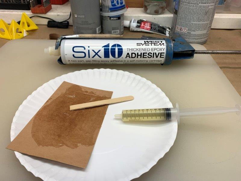
Six10 mixed on cardboard pad and stuffed into the syringe by removing the plunger and scraping the open syringe tube over the epoxy till its all in. Wipe off the base of the syringe and insert plunger.
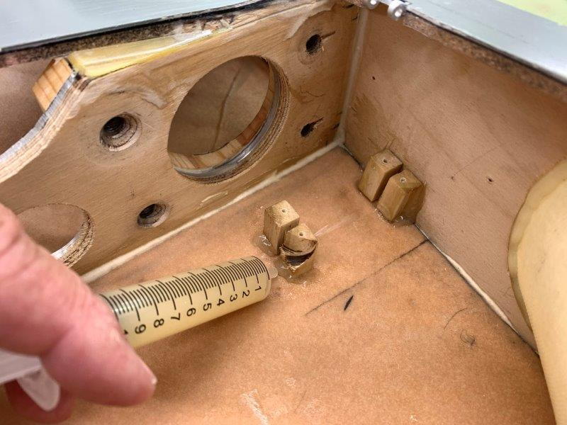
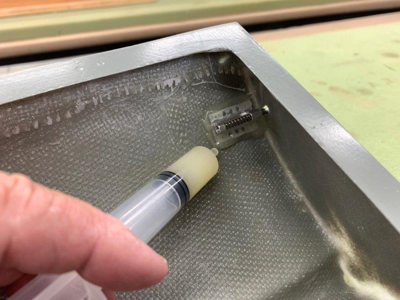
Applying glue fillet around base of gear door servo mounts
Same on canopy latches and dowels. It did an great job on the fuse former and drag chute door hinges also. Don't have and technical data on it but it seems as good or better than Hysol 9462 at less cost.
I first used Six10 about 5 years ago on my Sabre XLT project and thought it was pretty good. For the past several years I was using Hysol 9462 for thickened epoxy uses just because it seemed everybody else used it.
Last week I found I was almost out of Hysol and needed to do some "house keeping" gluing to lots of items I had just tack glued for fitting, including the vertical fin former recently installed. I recently got a box of 100 10ml syringes for about $14 on Amazon. I planned on using them for mixing my own thickened epoxy after watching Paul A's videos converting the foamy T-33.
I decided to use the Six10 again with the syringes and found it to be really good and much easier use than before with out the syringes. And then I figured the price per ml again and I'm really sold this time. Hysol is $16-$20 per 50ml tube. Six10 is $25-$28 per 190ml tube depending on where I can get it. I figure it's about half price and seems to do just as well. I can stuff the syringe for that.
Six10 mixed on cardboard pad and stuffed into the syringe by removing the plunger and scraping the open syringe tube over the epoxy till its all in. Wipe off the base of the syringe and insert plunger.
Applying glue fillet around base of gear door servo mounts
Same on canopy latches and dowels. It did an great job on the fuse former and drag chute door hinges also. Don't have and technical data on it but it seems as good or better than Hysol 9462 at less cost.
Last edited by Viper1GJ; 06-08-2020 at 06:32 PM.
06-09-2020, 03:50 PM
#593
Thread Starter
My Feedback: (20)
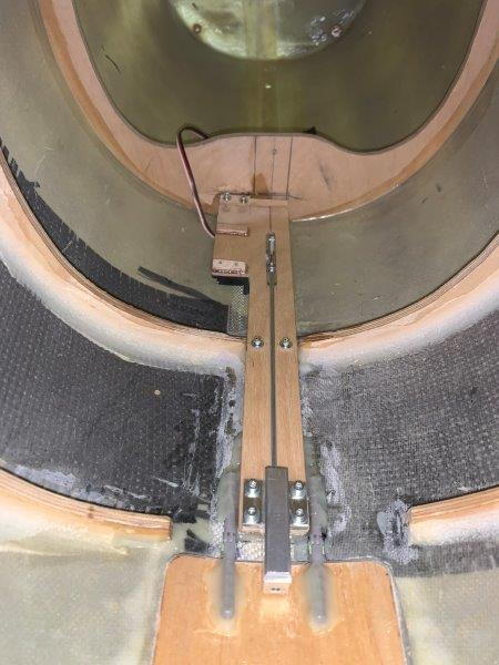
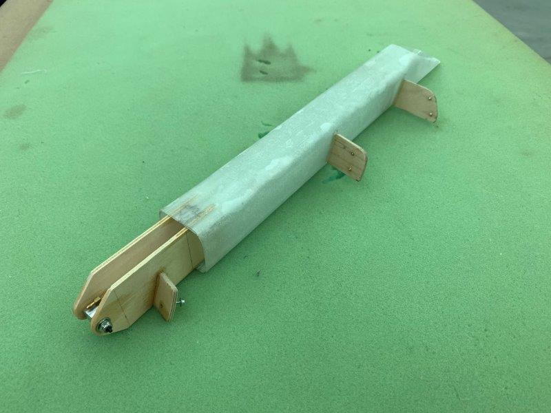
Mounting chute deployment tube
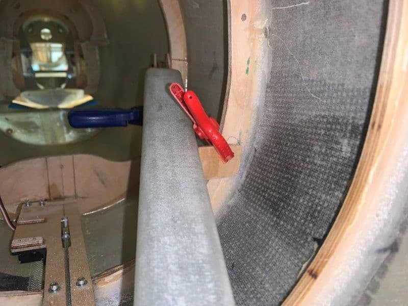
Clamps used to hole tube in place while plywood tabs were fabricated and glued to the tube to allow fastening to the fuse formers
Three tabs attached to the tube on proper angles to fasten to formers
Deployment tube fastened to formers
Clamps used to hole tube in place while plywood tabs were fabricated and glued to the tube to allow fastening to the fuse formers
Three tabs attached to the tube on proper angles to fasten to formers
Deployment tube fastened to formers
06-09-2020, 04:03 PM
#594
Thread Starter
My Feedback: (20)
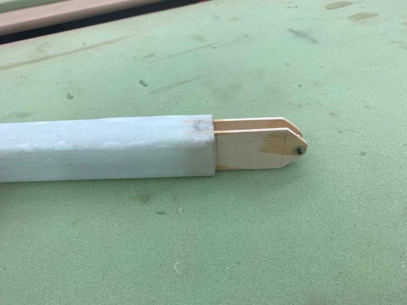
Trimming deployment tube to fit drag chute door
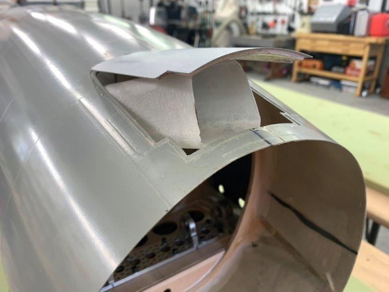
Tube sticks up through door with bottom edge flush with the fuse skin at the door trailing edge.
View directly into tube. Lines were marked on tube sides and top to fit under the door and tube removed and trimmed
Tube after trimming to fit door
Front end holding air ram
Tube now fits just under the closed door
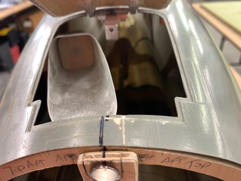
The chute will deploy over the aft edge of the fuse with lines attached to the chute release in center
Tube sticks up through door with bottom edge flush with the fuse skin at the door trailing edge.
View directly into tube. Lines were marked on tube sides and top to fit under the door and tube removed and trimmed
Tube after trimming to fit door
Front end holding air ram
Tube now fits just under the closed door
The chute will deploy over the aft edge of the fuse with lines attached to the chute release in center
06-09-2020, 04:14 PM
#595
Thread Starter
My Feedback: (20)
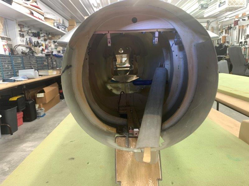
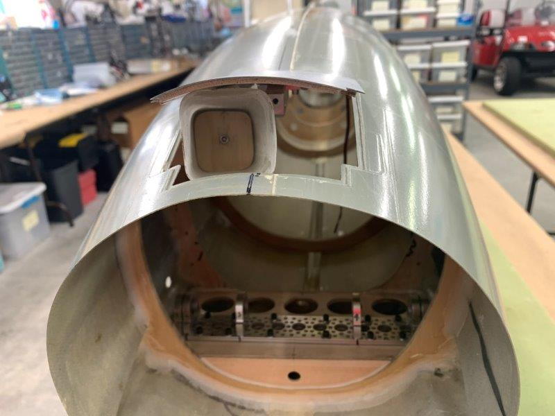
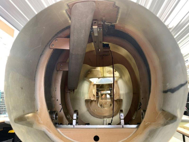
Pipe clearance
I tried to install the pipe to check final clearance from the chute tube and found it would not go in the fuse anymore because the bell would not fit between the chute tube and the stab bearings. After much fussing I found I could slightly squeeze the bell funnel and get it by. Thought I had built a show stopper for a while since I never considered getting the bell past the chute tube at all.
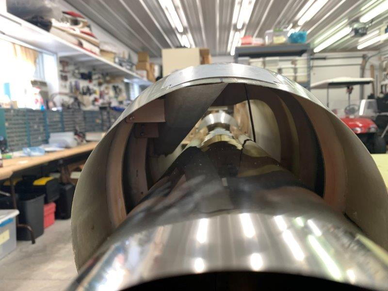
Good clearance from pipe outer tube as planned.

Rear former inserted to check with pipe in proper place
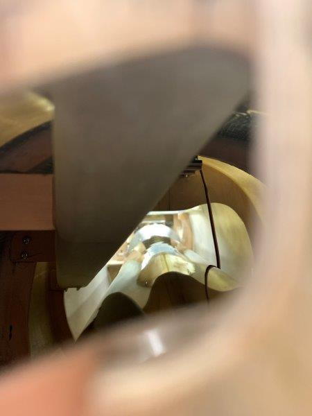
View through the rear former
Next is the magnet release for the chute door.
Done for the week for family vacation with grand kids to Myrtle Beach through the weekend.
I tried to install the pipe to check final clearance from the chute tube and found it would not go in the fuse anymore because the bell would not fit between the chute tube and the stab bearings. After much fussing I found I could slightly squeeze the bell funnel and get it by. Thought I had built a show stopper for a while since I never considered getting the bell past the chute tube at all.
Good clearance from pipe outer tube as planned.
Rear former inserted to check with pipe in proper place
View through the rear former
Next is the magnet release for the chute door.
Done for the week for family vacation with grand kids to Myrtle Beach through the weekend.
Last edited by Viper1GJ; 06-09-2020 at 04:18 PM.
06-12-2020, 12:05 AM
#596

Ditto on the West system Six10. We use a lot of it on my job, mostly for UAV use. We have even printed a small nozzle for the cartridge, so that it is easier to squeeze out smaller quantities on a paper. The resin hardener ratio seem to be 2:1.
Lars
Lars
 06-12-2020, 03:44 PM
#599
They are made by Pacer and go on the end of your CA bottles. They come in packages of 10 typically. Not inexpensive there may be a generic option available. I used to throw them into orders from Tower when i ordered from them usually to push me to some $$ total for a coupon. Lol