


1/6 F-105 Build Thread
 05-26-2020, 05:22 PM
#551

Thread Starter
My Feedback: (20)
Tank volume calculation and air duct planning
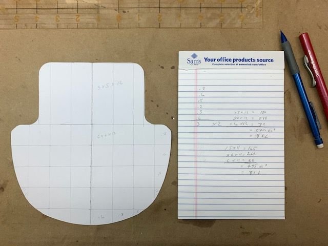
I estimated the square inches on the template just by eyeballing the squares and estimated between 8.8 and 8.1 liters with out taper in the rear. If the taper shape reduces volume by 20% I will still have over 6.5 liters which is plenty. My Havoc has 6.2 and BVM F-16 has 6.8, both are plenty.
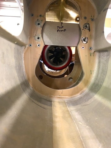
I took the K-320 out of the F-16 and installed here to estimate the air flow path and depth of the tank at the rear former.
I estimate I can use half the distance from the bottom of the fuse to the top of the rear of the tank and still have plenty of air flow to the turbine below the spar. AIr can also flow over the top of the spar to the turbine.
I estimated the square inches on the template just by eyeballing the squares and estimated between 8.8 and 8.1 liters with out taper in the rear. If the taper shape reduces volume by 20% I will still have over 6.5 liters which is plenty. My Havoc has 6.2 and BVM F-16 has 6.8, both are plenty.
I took the K-320 out of the F-16 and installed here to estimate the air flow path and depth of the tank at the rear former.
I estimate I can use half the distance from the bottom of the fuse to the top of the rear of the tank and still have plenty of air flow to the turbine below the spar. AIr can also flow over the top of the spar to the turbine.
 05-26-2020, 05:25 PM
#552
Thread Starter
My Feedback: (20)
Enlarging cockpit opening
I measured and plotted a larger cockpit opening to get the tank through the hole
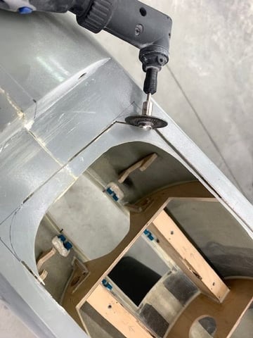
Dremel cutting wheel used to make rough cuts
Cut piece removed
Corners rounded and sanded
I measured and plotted a larger cockpit opening to get the tank through the hole
Dremel cutting wheel used to make rough cuts
Cut piece removed
Corners rounded and sanded
05-26-2020, 05:52 PM
#553
Thread Starter
My Feedback: (20)
Making the tank plug
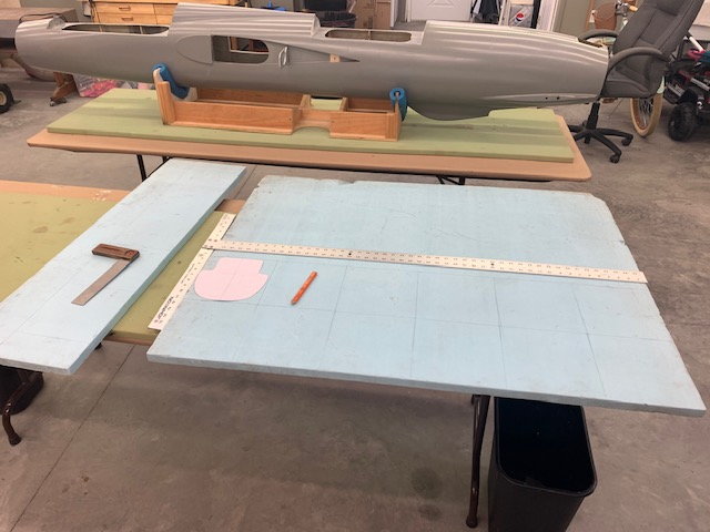
I had some old 1" blue foam left over from my Sabre XLT project so used it for the tank plug blanks
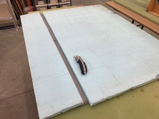
Foam scored with knife and snapped off
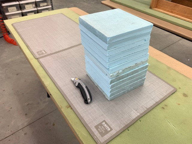
12 8" x 8" squares cut

I added a half inch height to the lower shoulder on the template to make use of the space available. I caculated about .2 L increase in volume for that. Then the patterns were traced on the foam blanks
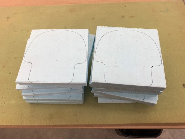
Ready for cutting
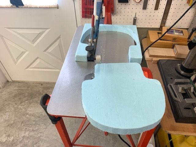
The scroll saw was faster than making templates and using a hot wire cutter. Low blade speed was easier to control and worked best. One down and 11 to go!
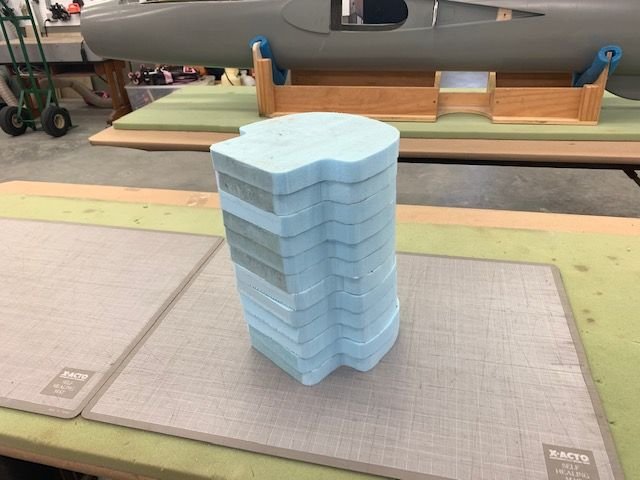
Cuts all done.
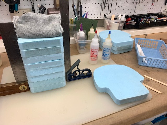
I used 5 min epoxy mixed right on the foam to bond the templates together
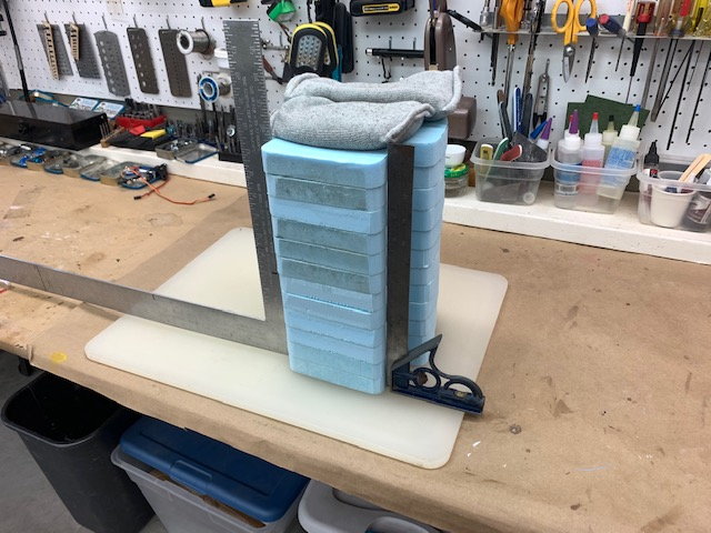
Each layer was aligned and squared up then weighted.
All done, ready to sand.
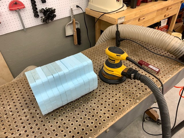
Sanding done on down draft table to control dust
1" dowel and 80 grit in inside curves
Rough sanding done with electric sander
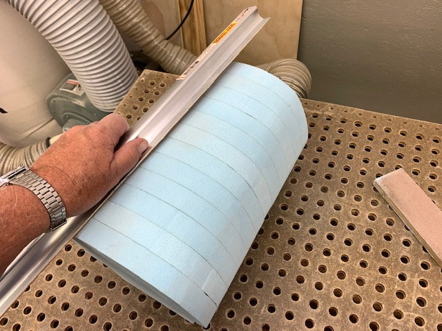
Bar sander smoothed out straight edges
Finished with 180 grit sanding sponge. Ready for rear end shaping.
I had some old 1" blue foam left over from my Sabre XLT project so used it for the tank plug blanks
Foam scored with knife and snapped off
12 8" x 8" squares cut
I added a half inch height to the lower shoulder on the template to make use of the space available. I caculated about .2 L increase in volume for that. Then the patterns were traced on the foam blanks
Ready for cutting
The scroll saw was faster than making templates and using a hot wire cutter. Low blade speed was easier to control and worked best. One down and 11 to go!
Cuts all done.
I used 5 min epoxy mixed right on the foam to bond the templates together
Each layer was aligned and squared up then weighted.
All done, ready to sand.
Sanding done on down draft table to control dust
1" dowel and 80 grit in inside curves
Rough sanding done with electric sander
Bar sander smoothed out straight edges
Finished with 180 grit sanding sponge. Ready for rear end shaping.
Last edited by Viper1GJ; 05-26-2020 at 05:54 PM.
05-26-2020, 06:06 PM
#554
Thread Starter
My Feedback: (20)
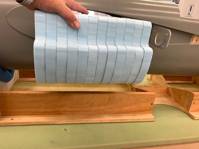
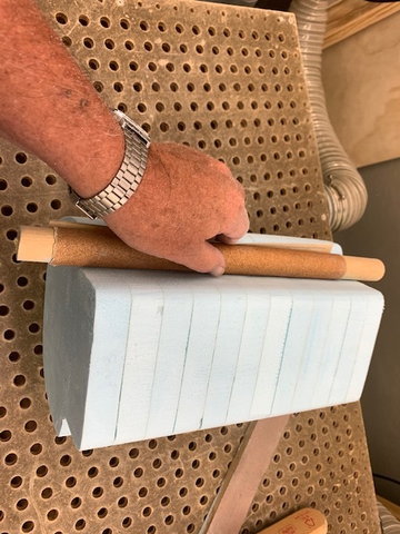
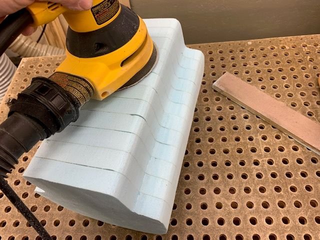
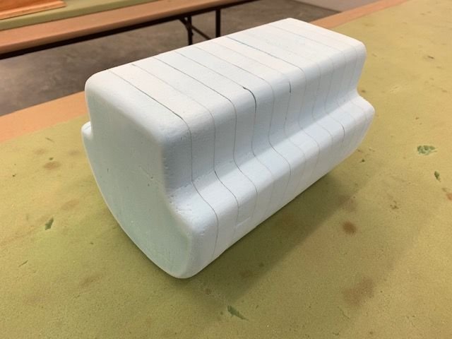
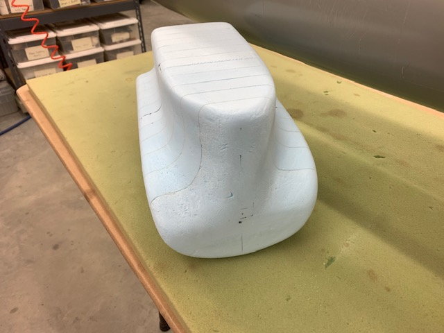
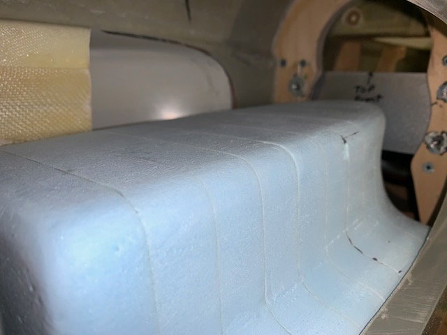
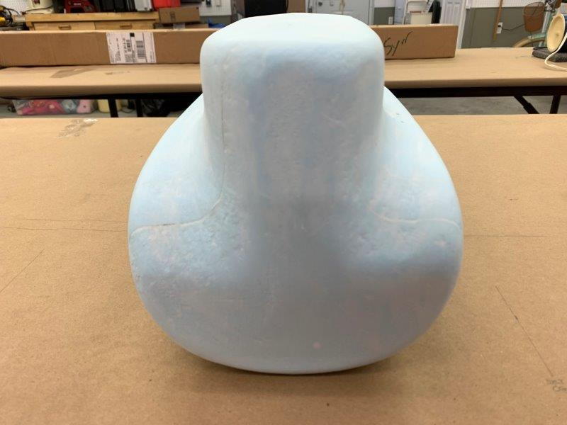
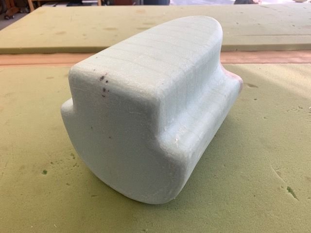
Shaping rear of tank plug
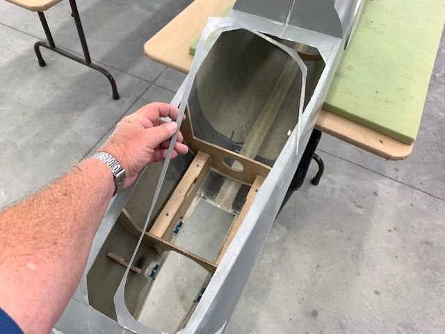
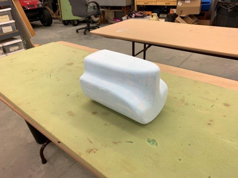
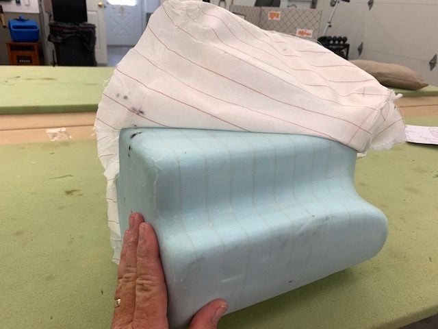
Plug fits through cockpit hole now
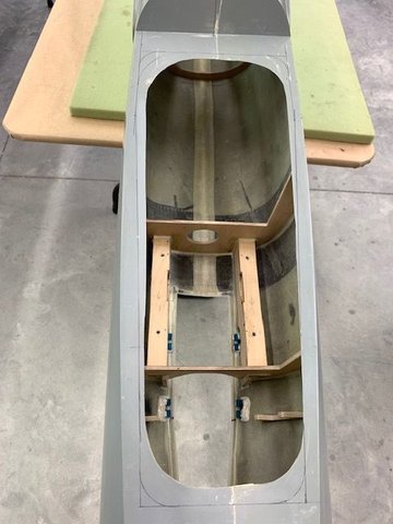
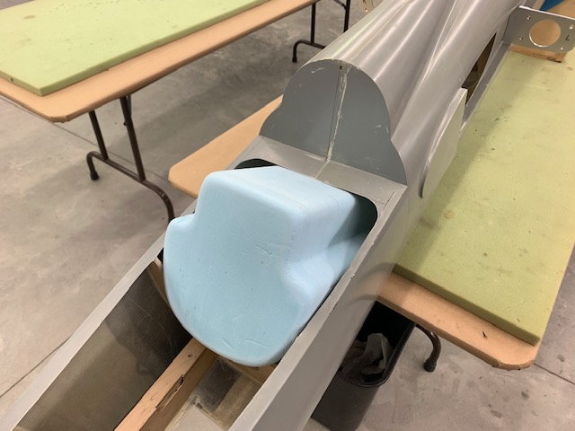
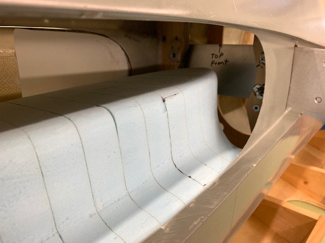
View from the front. Tank plug fits between wing air intakes and will be mounted slightly above the fuse bottom. Tank will be secured in place by a single Velcro One Wrap strap in the center.
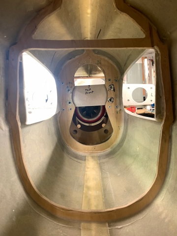
View from the rear. Tank plug covers the hole in the rear former so tank has to be tapered to allow air to enter below the aluminum spar.
Bottom of the turbine is about 1/2 distance up from the fuse bottom plotted here by the dowel on the foam.
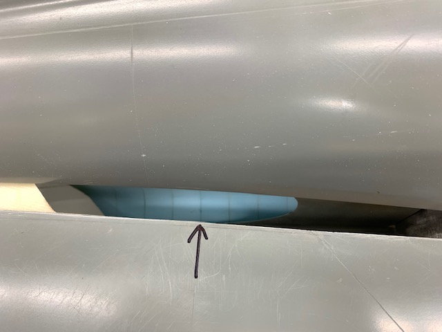
Taper needs to start at the tank mid point in the air intake
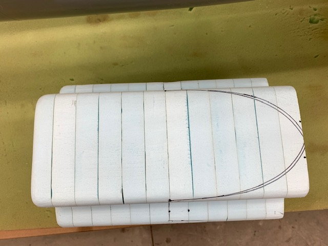
Top view. These plots were generated by multiple iterations of TLAR (That Looks About Right) analysis of aerodymanics and high end CAD (Come Along Design where the design comes along as I draw it) computations. The concept is if I were an air molecule could I follow this line? I think so.
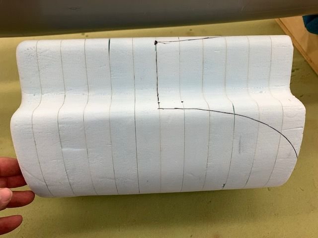
Side view
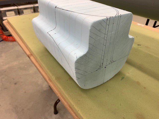
Taper plotted on top and sides of tank. Foam to be removed in hashed areas
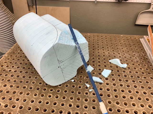
Back to the down draft table with a hack saw blade
Rough cuts done
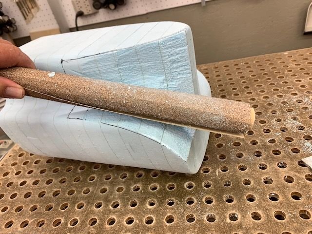
80 grit on 1" dowel completed the remaining shaping
Smoothed out with 180 sanding sponge ready for test fit
Plug fits through cockpit hole now
View from the front. Tank plug fits between wing air intakes and will be mounted slightly above the fuse bottom. Tank will be secured in place by a single Velcro One Wrap strap in the center.
View from the rear. Tank plug covers the hole in the rear former so tank has to be tapered to allow air to enter below the aluminum spar.
Bottom of the turbine is about 1/2 distance up from the fuse bottom plotted here by the dowel on the foam.
Taper needs to start at the tank mid point in the air intake
Top view. These plots were generated by multiple iterations of TLAR (That Looks About Right) analysis of aerodymanics and high end CAD (Come Along Design where the design comes along as I draw it) computations. The concept is if I were an air molecule could I follow this line? I think so.
Side view
Taper plotted on top and sides of tank. Foam to be removed in hashed areas
Back to the down draft table with a hack saw blade
Rough cuts done
80 grit on 1" dowel completed the remaining shaping
Smoothed out with 180 sanding sponge ready for test fit
Last edited by Viper1GJ; 05-26-2020 at 06:24 PM.
05-26-2020, 06:15 PM
#555
Thread Starter
My Feedback: (20)
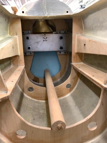
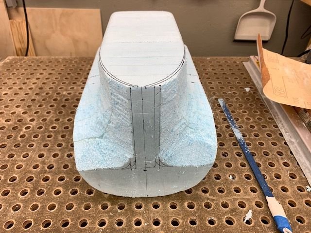
Tank plug dry fit
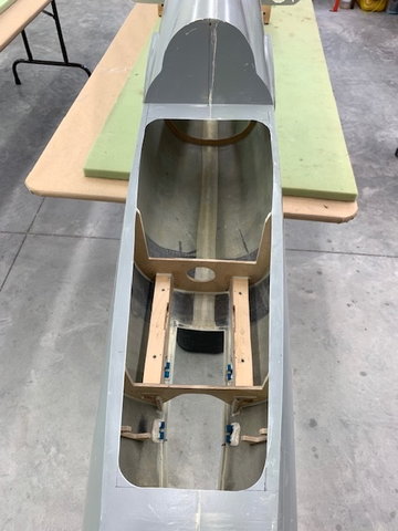
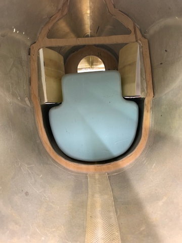
Air channel along side of tank and down below the aluminum spar
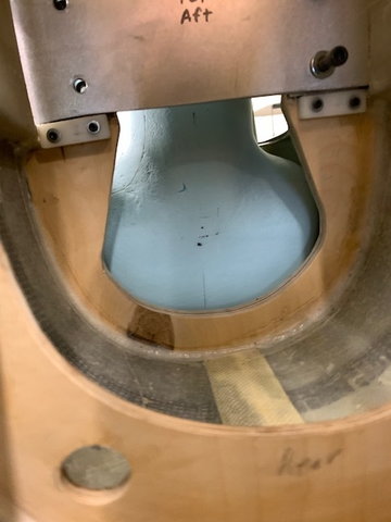
View from the rear at the turbine intake. Air channels allow air to enter on both sides and flow below the spar into the turbine intake
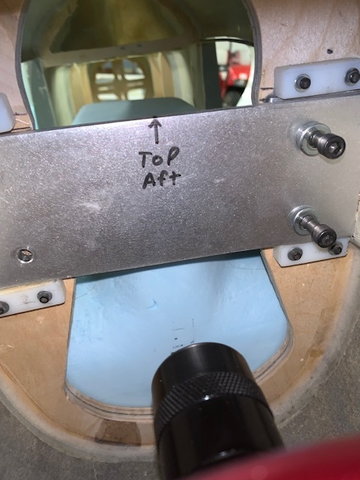
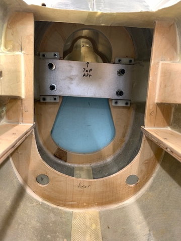
View from the turbine inlet above the spar
Lots of space above the tank and above the spar for air to enter
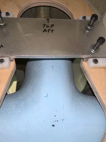
This view makes me think I need to increase the air channels some more, but that will shave some fuel capacity a little. Since the air molecules in my brain have slowed down a lot over the last few years and have gained much weight I think they may need a little more room to squeeze through. Still thinking about it. Any advice appreciated.
Air channel along side of tank and down below the aluminum spar
View from the rear at the turbine intake. Air channels allow air to enter on both sides and flow below the spar into the turbine intake
View from the turbine inlet above the spar
Lots of space above the tank and above the spar for air to enter
This view makes me think I need to increase the air channels some more, but that will shave some fuel capacity a little. Since the air molecules in my brain have slowed down a lot over the last few years and have gained much weight I think they may need a little more room to squeeze through. Still thinking about it. Any advice appreciated.
Last edited by Viper1GJ; 05-26-2020 at 06:27 PM.
The following users liked this post:
[email protected] (05-26-2020)
 05-27-2020, 04:48 AM
#557

You could probably block one whole intake and still have enough air getting to turbine. If you’re concerned with fuel total you could add another header tank on top of the main tank. Keep up great work, you’re workshop has inspired me to rethink the layout of the one I intend to build sometime next year.
05-27-2020, 05:54 AM
#558

I think you�ll be fine with what you have currently. You really only need as much surface area for the inlets as the compressor has surface area as the jet efflux and the turbine itself will suck the air you need from wherever it can get it from. Its not like an EDF that needs smooth transitions to be efficient.
 05-27-2020, 05:37 PM
#560
Thread Starter
My Feedback: (20)
Thanks for the compliments and tips guys. I really appreciate it.
I did some quick TLAR calculations again today and estimate I have about 3 times the area of the turbine inlet available for air to go over or under the wing spar and came to the same conclusion that Thomas stated. The air will find a way in there ok. My Sabre XLT basically works the same way as there are no intakes at all, just two holes on the side of the fuse and the turbine just sucks it in.
I sanded the plug some more today to enlarge the air channels a little more but mostly to get better draft angles on the plug for removing the glass from the plug after cured. Since I am a novice at composite fabrication, Paul Appelbaum has been very helpful coaching me on tank making. He saw I did not have any draft angles on the initial plug so I sanded the flat surfaces to make release draft angles. Paul makes outstanding tanks for the foamie conversions so I'm mostly copying his process.
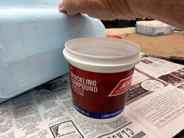
I rubbed the foam plug with lighweight spackle to fill the cracks and dents. I will sand smooth and glass the plug next.
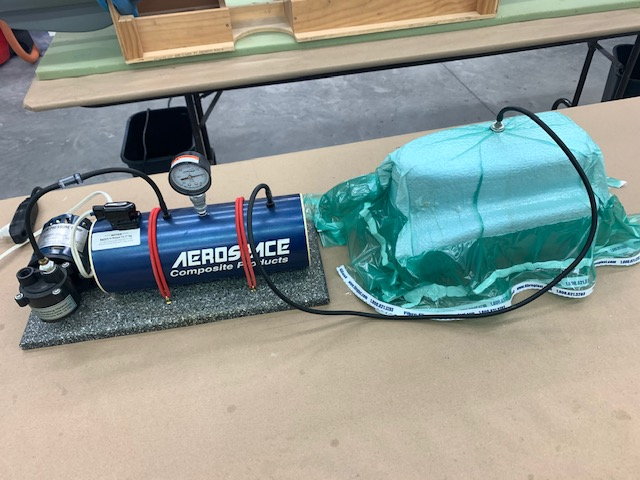
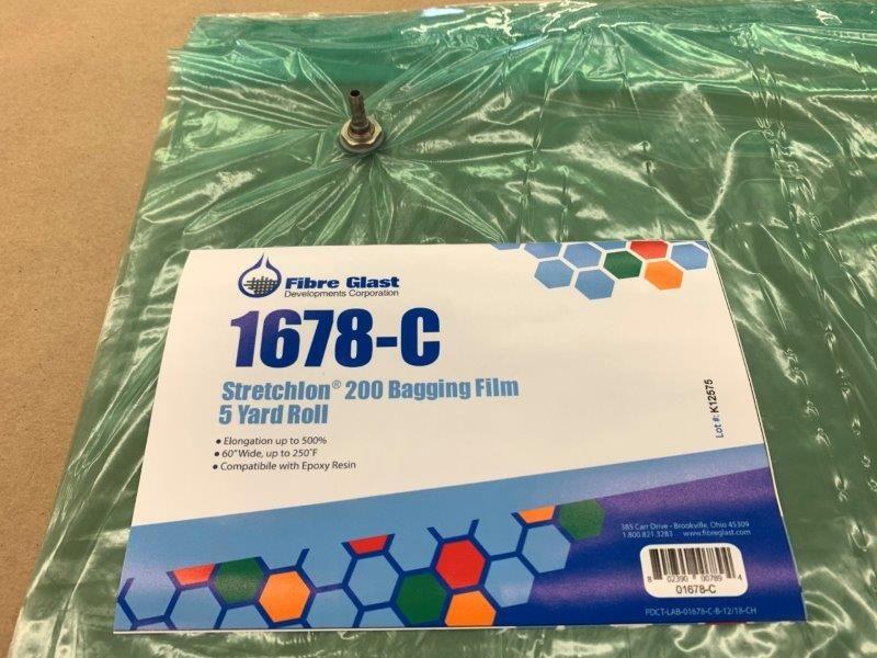
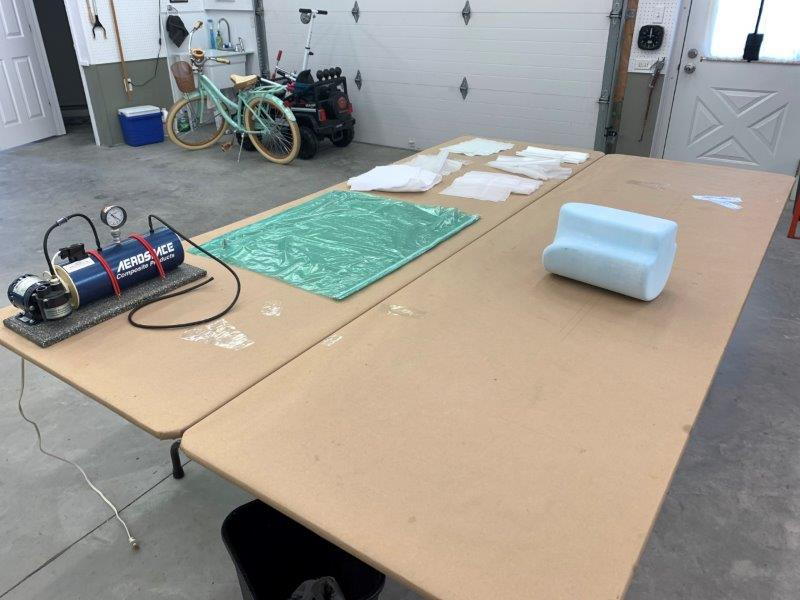
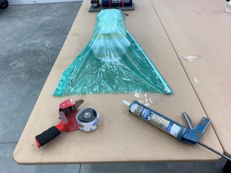
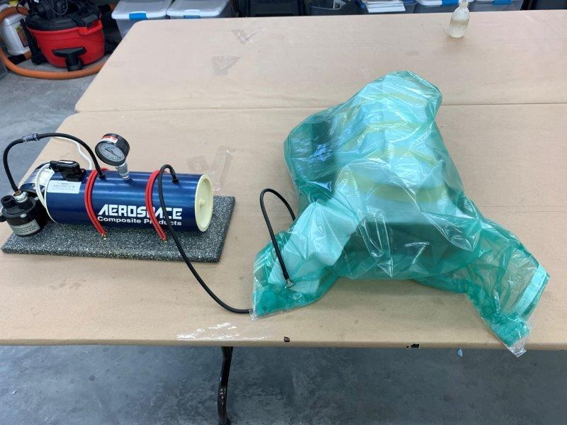
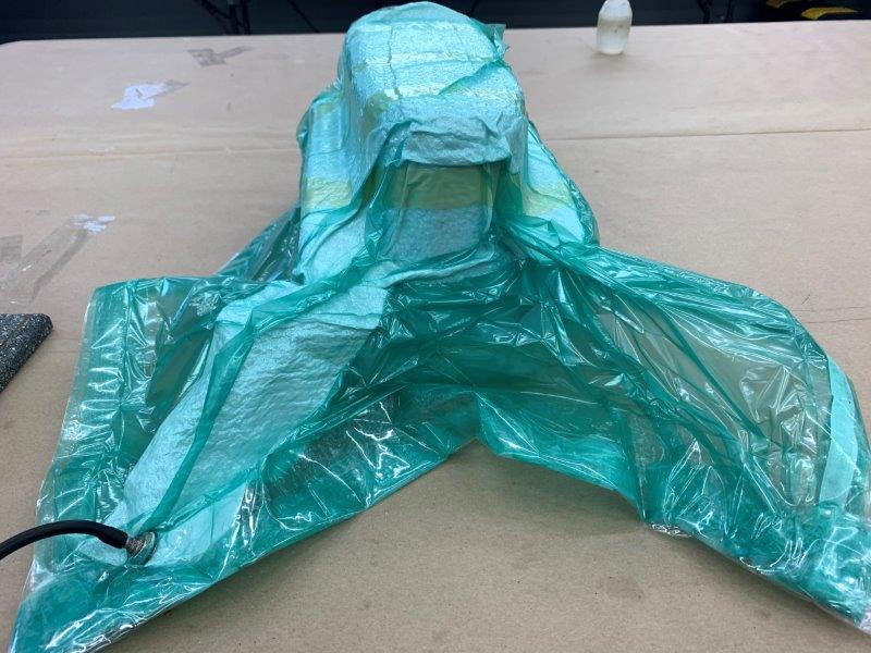
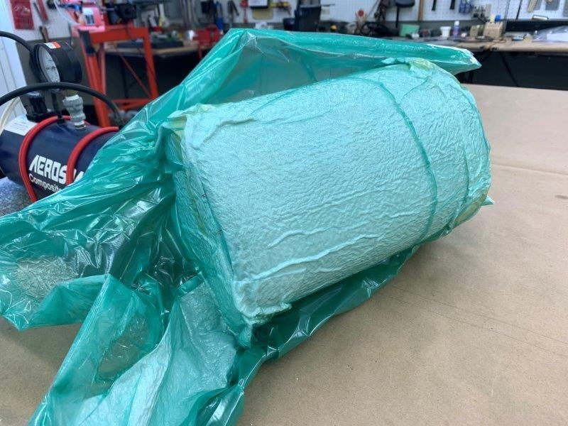
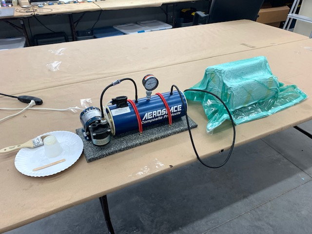
I bought some Strechlon 200 bagging film about a year ago but never tried it. I did a simple DRY bagging test to see if the film would cover the shape of the tank, and it did very well. I plan to vacuum bag the plug to keep the glass and peel ply down during cure.
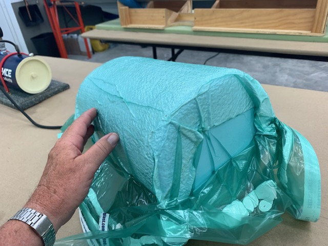
I used some left over caulk to seal the bag for the test. I'll trim the breather cloth better for the wet layup.
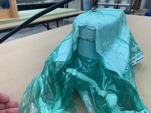
Should work ok.
I did some quick TLAR calculations again today and estimate I have about 3 times the area of the turbine inlet available for air to go over or under the wing spar and came to the same conclusion that Thomas stated. The air will find a way in there ok. My Sabre XLT basically works the same way as there are no intakes at all, just two holes on the side of the fuse and the turbine just sucks it in.
I sanded the plug some more today to enlarge the air channels a little more but mostly to get better draft angles on the plug for removing the glass from the plug after cured. Since I am a novice at composite fabrication, Paul Appelbaum has been very helpful coaching me on tank making. He saw I did not have any draft angles on the initial plug so I sanded the flat surfaces to make release draft angles. Paul makes outstanding tanks for the foamie conversions so I'm mostly copying his process.
I rubbed the foam plug with lighweight spackle to fill the cracks and dents. I will sand smooth and glass the plug next.
I bought some Strechlon 200 bagging film about a year ago but never tried it. I did a simple DRY bagging test to see if the film would cover the shape of the tank, and it did very well. I plan to vacuum bag the plug to keep the glass and peel ply down during cure.
I used some left over caulk to seal the bag for the test. I'll trim the breather cloth better for the wet layup.
Should work ok.
Last edited by Viper1GJ; 05-27-2020 at 05:41 PM.
05-29-2020, 05:01 PM
#562
Thread Starter
My Feedback: (20)
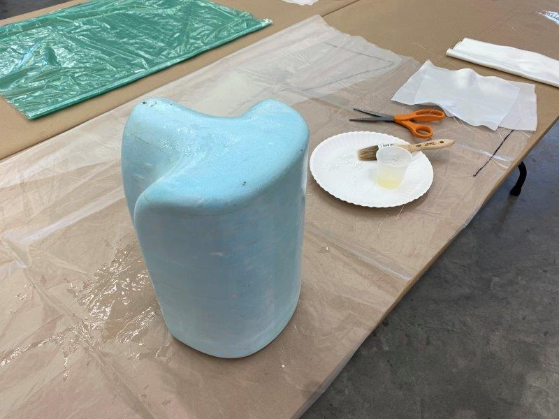
Glass Prep
Tank plug ready for glassing
I sanded more taper on the draft angles on surfaces to assist in part removal form plug
Also a little more taper in the rear to open up air channels
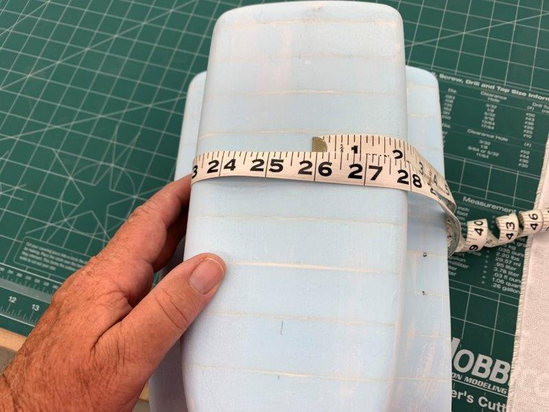
Measuring for glass cutting
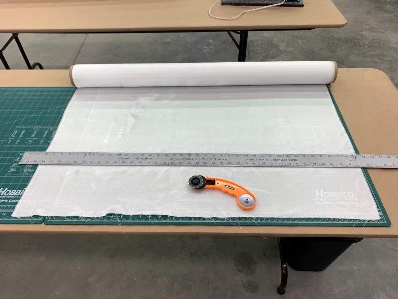
Cutting glass with rotary cutter
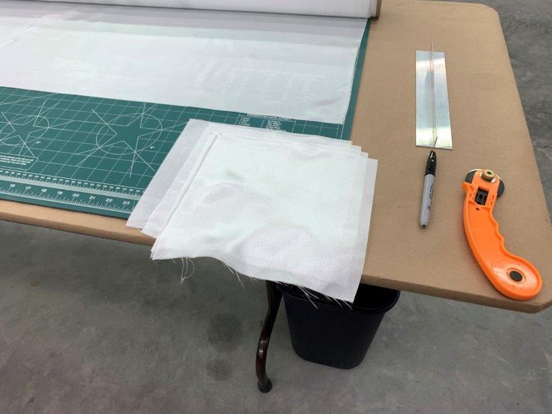
Glass end pieces cut
Peel ply cut
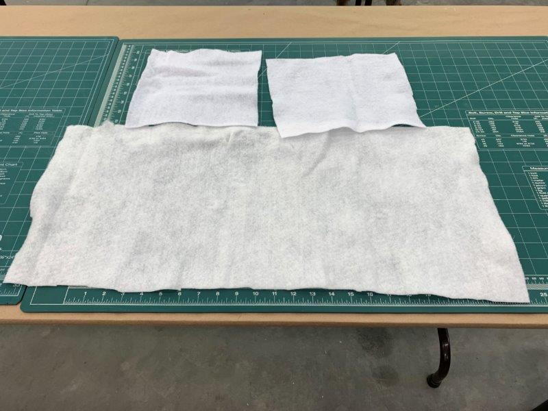
Breather cloth cut
Tank plug ready for glassing
I sanded more taper on the draft angles on surfaces to assist in part removal form plug
Also a little more taper in the rear to open up air channels
Measuring for glass cutting
Cutting glass with rotary cutter
Glass end pieces cut
Peel ply cut
Breather cloth cut
05-29-2020, 05:13 PM
#563
Thread Starter
My Feedback: (20)
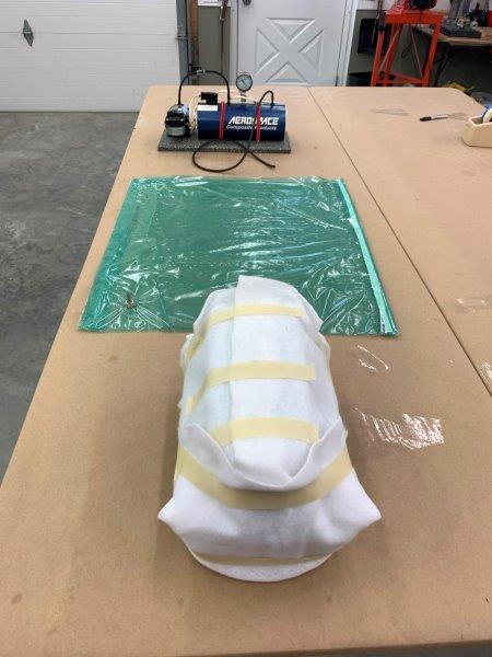
Bag and layup prep
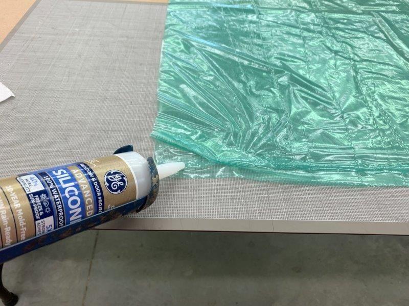
Vacuum bag prepped using silicon caulk to seal edges
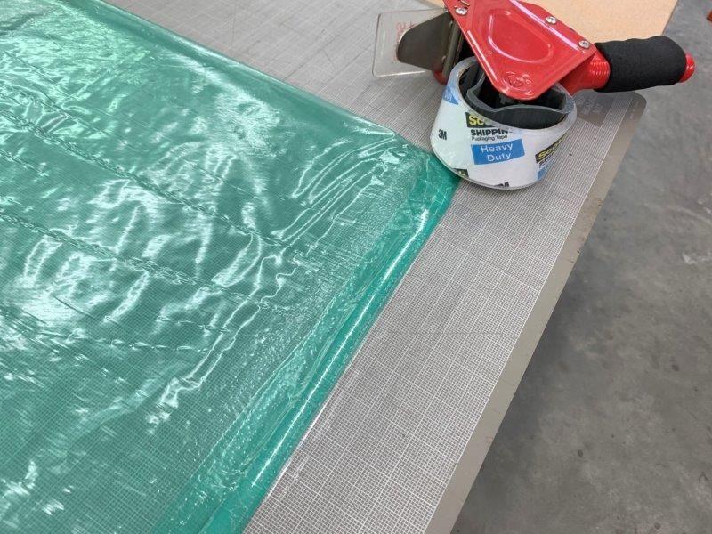
Bag edges folded over and taped with packing tape
Vacuum nipple inserted and secured to top layer of bag film
Bag and glass cuttings ready
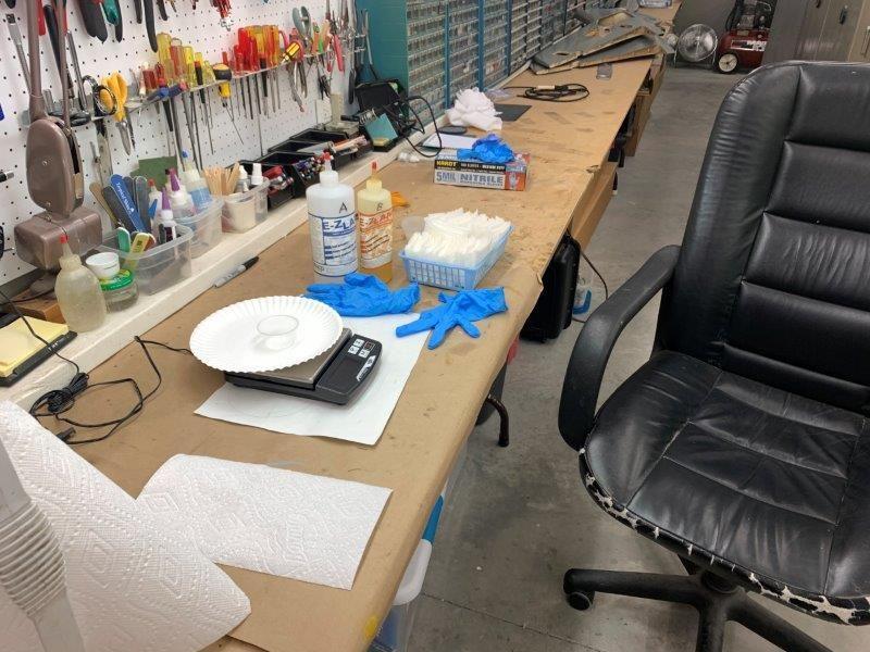
Epoxy mixing area ready
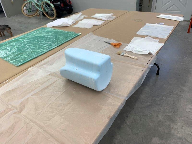
Work table covered with plastic and ready. Every time I get ready to use laminating epoxy I feel like I'm prepping for a disaster. I don't have much experience doing composites so I always have a fear of it all going wrong. So here we go.
Vacuum bag prepped using silicon caulk to seal edges
Bag edges folded over and taped with packing tape
Vacuum nipple inserted and secured to top layer of bag film
Bag and glass cuttings ready
Epoxy mixing area ready
Work table covered with plastic and ready. Every time I get ready to use laminating epoxy I feel like I'm prepping for a disaster. I don't have much experience doing composites so I always have a fear of it all going wrong. So here we go.
05-29-2020, 05:30 PM
#564
Thread Starter
My Feedback: (20)
Glassing and bagging
First layer of glass applied, 2 to go
All three layers applied ready for peel ply
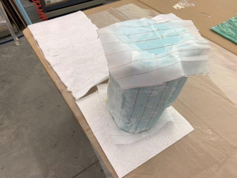
Peel ply applied. I never used it before so I really did not know how to do it so I just stuck it on and overlapped ends
Breather cloth applied and taped in place. Ready to place plug in vacuum bag.
Open end of bag sealed with silicone caulk and tape. I forgot to put the bleeder cloth run from the plug to the air fitting so I had to pull the bag open again and then reseal. That got messy with the caulk.
Pump turned on and air getting sucked out.
AIr sucked out to 7" hg and holding. I was elated. No leaks.
Bottom side sucked up pretty good.
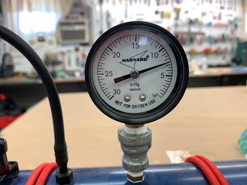
Pressure holding good. After about 5 minutes pressure would drop to 5 and pump would run for about 2-3 seconds and push it back to 7 and repeat. Seems to be working ok. Left it for the next day.
First layer of glass applied, 2 to go
All three layers applied ready for peel ply
Peel ply applied. I never used it before so I really did not know how to do it so I just stuck it on and overlapped ends
Breather cloth applied and taped in place. Ready to place plug in vacuum bag.
Open end of bag sealed with silicone caulk and tape. I forgot to put the bleeder cloth run from the plug to the air fitting so I had to pull the bag open again and then reseal. That got messy with the caulk.
Pump turned on and air getting sucked out.
AIr sucked out to 7" hg and holding. I was elated. No leaks.
Bottom side sucked up pretty good.
Pressure holding good. After about 5 minutes pressure would drop to 5 and pump would run for about 2-3 seconds and push it back to 7 and repeat. Seems to be working ok. Left it for the next day.
05-29-2020, 05:58 PM
#565
Thread Starter
My Feedback: (20)
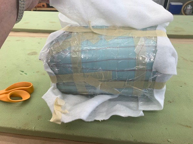
Removing peel ply and plug repairs
Well here is the disaster. I disconnected the pump and opened the bag. I found the breather cloth and peel ply were completely bonded to the plug. I could not find a way to get it off. After about 30 mins I discovered I could pull small parts off with a pair of pliers.
After about 2 hours I finally got to where I could get some big pieces off. Clearly I did something wrong. I had considered trashing the whole thing and starting over but I finally made some progress.
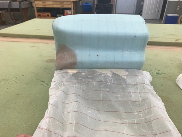
Finally got to the big piece and it came off easier.
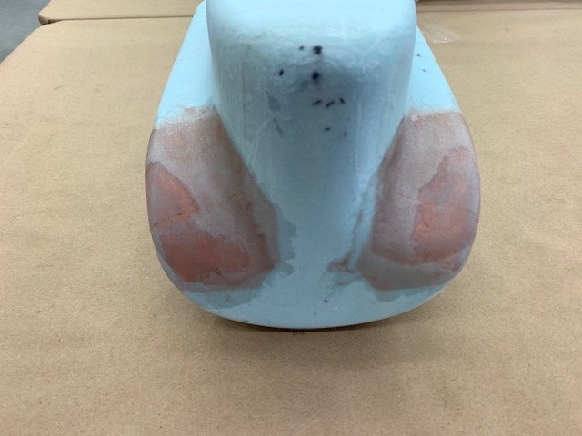
After some sanding and inspection I discovered I had no draft angle at all on the rear shoulders so I sanded through the glass into the foam and reshaped the corner. I used West 205 wtth the red tint to make a quick repair with two layers of glass. After discussing the plug prep with Paul I plan to add tow more layers of glass to give a very strong surface on the plug. Hopefully this will make it less likely to damage the plug when removing the tank halves from the plug. Rookie mistakes again.
Well here is the disaster. I disconnected the pump and opened the bag. I found the breather cloth and peel ply were completely bonded to the plug. I could not find a way to get it off. After about 30 mins I discovered I could pull small parts off with a pair of pliers.
After about 2 hours I finally got to where I could get some big pieces off. Clearly I did something wrong. I had considered trashing the whole thing and starting over but I finally made some progress.
Finally got to the big piece and it came off easier.
After some sanding and inspection I discovered I had no draft angle at all on the rear shoulders so I sanded through the glass into the foam and reshaped the corner. I used West 205 wtth the red tint to make a quick repair with two layers of glass. After discussing the plug prep with Paul I plan to add tow more layers of glass to give a very strong surface on the plug. Hopefully this will make it less likely to damage the plug when removing the tank halves from the plug. Rookie mistakes again.
05-30-2020, 02:26 PM
#567
Thread Starter
My Feedback: (20)
Second glass layups on tank plug
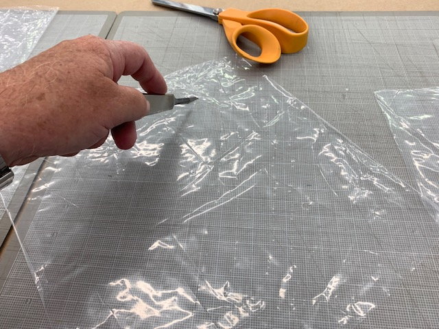
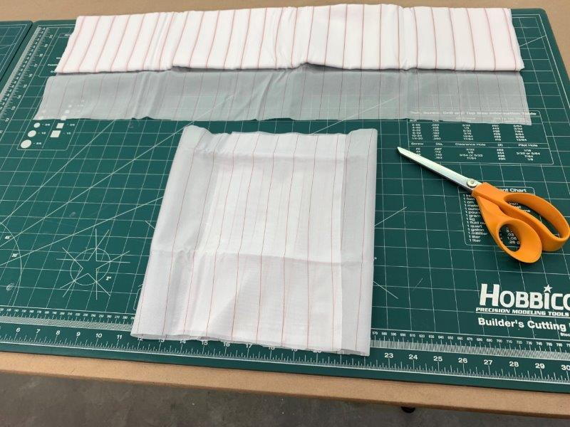
I took Thomas's recommendation and made some perforated release film. I studied up on the stuff and how to use it and saw some photos of it. I made some homemade film by hacking up some plastic film on the cutting board using the lines as a rough guide and making "dotted cut lines" on the film perpendicular to each other.
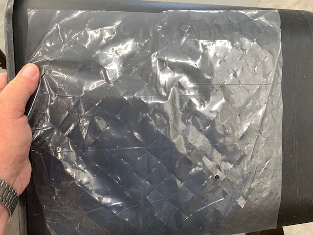
My cut pattern shown here against the black trash can.
I did 3 more layers as before and then added peel ply, perforated release film, bleeder cloth and stuffed it in the same bag as before.
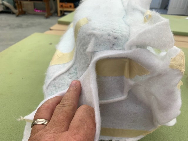
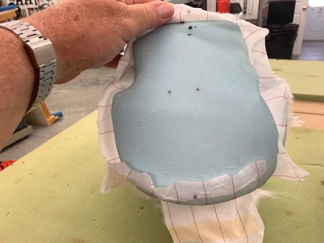
WOW! What a difference a little knowledge makes. Thanks Thomas for the tip. This time the breather cloth came off easy.
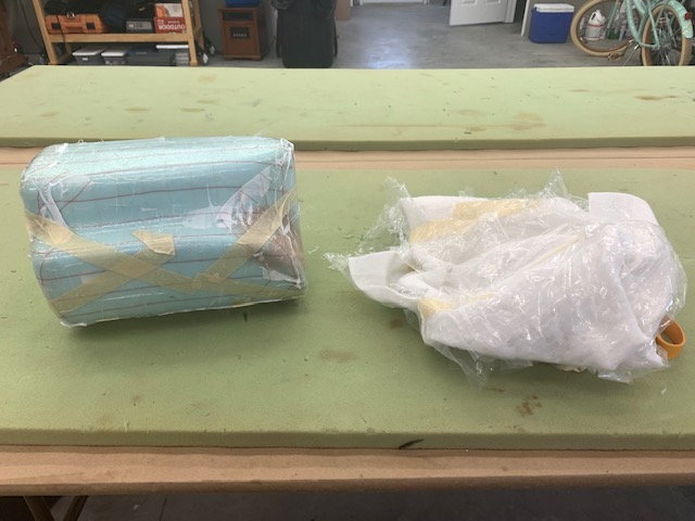
The release film pulled right off no problem
The peel ply was a little tougher but no real problem. All off in about 5 min vs 2 hours as before. Plug ready for sanding and body work. Thanks again!
Gary
I took Thomas's recommendation and made some perforated release film. I studied up on the stuff and how to use it and saw some photos of it. I made some homemade film by hacking up some plastic film on the cutting board using the lines as a rough guide and making "dotted cut lines" on the film perpendicular to each other.
My cut pattern shown here against the black trash can.
I did 3 more layers as before and then added peel ply, perforated release film, bleeder cloth and stuffed it in the same bag as before.
WOW! What a difference a little knowledge makes. Thanks Thomas for the tip. This time the breather cloth came off easy.
The release film pulled right off no problem
The peel ply was a little tougher but no real problem. All off in about 5 min vs 2 hours as before. Plug ready for sanding and body work. Thanks again!
Gary
05-30-2020, 02:33 PM
#568
Thread Starter
My Feedback: (20)
I will make a left and right tank half off the male plug after I get the body work done and it is finished and waxed.
I'm looking for recommendations for what glass weights and how many layers would be needed to make a sturdy tank. The size is about 8" x 8" x 12" and capacity about 7-8 liters. Its a large tank so I'm asking what weights and layers you experienced composite guys would use.
Thanks,
Gary
I'm looking for recommendations for what glass weights and how many layers would be needed to make a sturdy tank. The size is about 8" x 8" x 12" and capacity about 7-8 liters. Its a large tank so I'm asking what weights and layers you experienced composite guys would use.
Thanks,
Gary
 05-30-2020, 07:34 PM
#570
Join Date: Jan 2004
Location: Mt. Vernon, IL
Posts: 491
Likes: 0
Received 0 Likes
on
0 Posts
With that shape I would use 4 or 5 layers of 4 oz cloth lot easier to get it to lay down in those compound curves. You will most likely have to do the flat end with separate pieces to get it to fit nicely in the corners. Also a couple of extra layers wherever you plan on putting the tank fittings. I would also offset any fittings where they do not go through a seam.
05-31-2020, 05:20 AM
#571
I would probly do 2 layers of
3.16oz style 220
2 layers of
5.8oz style 3733
following my a final layer of the style 220.
both of those fabrica are very easy to work with, conform will and are fairly inexpensive from www.thayercraft.com
3.16oz style 220
2 layers of
5.8oz style 3733
following my a final layer of the style 220.
both of those fabrica are very easy to work with, conform will and are fairly inexpensive from www.thayercraft.com
06-01-2020, 03:57 PM
#573
Thread Starter
My Feedback: (20)
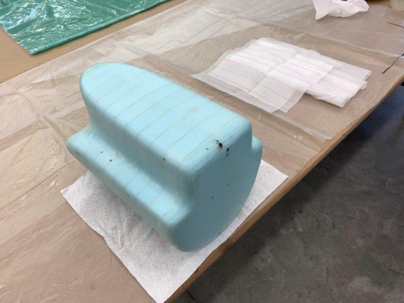
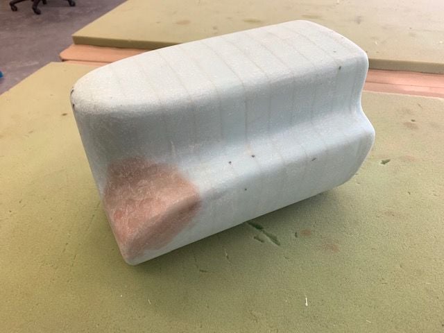
Plug primed, filled, sanded
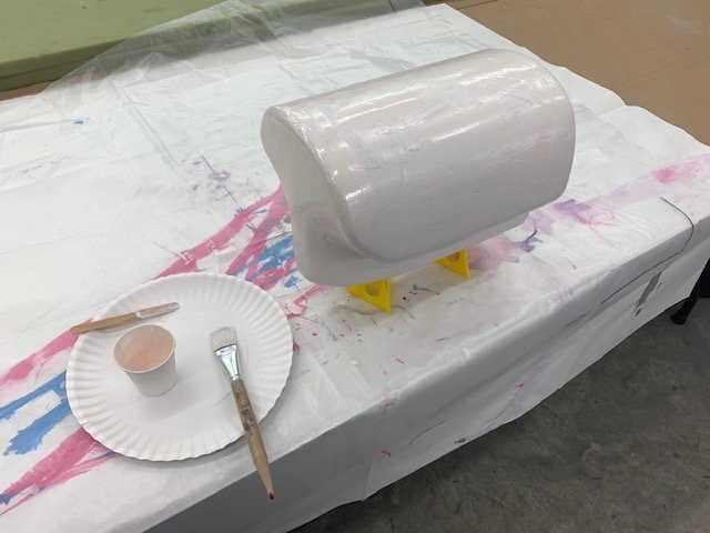
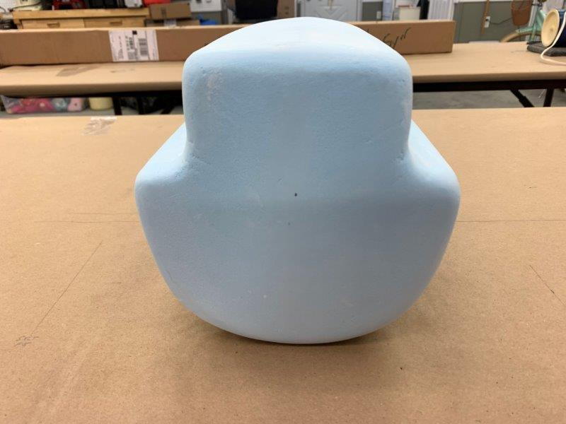
Plug got first coat of white KlassKote epoxy primer for a base coat
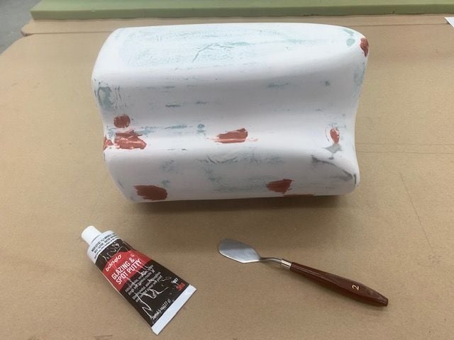
Wet sanded, dings filled with glazing putty and sanded again
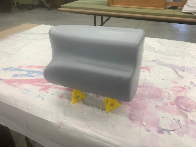
2nd and 3rd coats of 2K auto primer wet sanded and filled between coats.
Plug got first coat of white KlassKote epoxy primer for a base coat
Wet sanded, dings filled with glazing putty and sanded again
2nd and 3rd coats of 2K auto primer wet sanded and filled between coats.
06-01-2020, 05:04 PM
#574
And all this beautiful work for a plug for a fuel tank!
Artistry my man, simply wonderful.
Gawd, I'd love to be able to build like this some day. My last tank (smoke) and only tank I made from a foam plug looks like it survived a direct mortar strike with so many crevices and nooks and crannies.....And that was on the OUTSIDE! LOL
Artistry my man, simply wonderful.
Gawd, I'd love to be able to build like this some day. My last tank (smoke) and only tank I made from a foam plug looks like it survived a direct mortar strike with so many crevices and nooks and crannies.....And that was on the OUTSIDE! LOL
06-02-2020, 05:23 AM
#575
Thread Starter
My Feedback: (20)
Thanks Rav,
It’s getting there. I’ve only done tanks once before. I made smoke tanks for my SM 1/5 F-16 a couple years ago. I used lost foam process then. I’ve never made and finished a plug before. I’m following Paul Appelbaum’s advice trying to make sure you can get the molded part off the plug with out destroying it or the plug. So to pop it off ok there must not have any places that can form a “hook” that will lock the part on the plug. Any way it’s a lot of work. It would be cool to 3D print it but I could make this faster than I could learn to do that.
Gary