


1/6 F-105 Build Thread
 02-20-2020, 05:11 PM
#526

Thread Starter
My Feedback: (20)
Drag chute door.
I gave up on the gear doors for a while and started on something I thought I could get to work...the drag chute system. I had planned at first not to do one, but since Dave made such a cool Lua program to make it work with the Jeti radio I could not resist trying. My concept is to use the Skymaster 1/6 F-4 drag chute hardware and adapt it to the F-105 fuse. Issues are fitting the hardware in above the pipe and protecting it from heat.
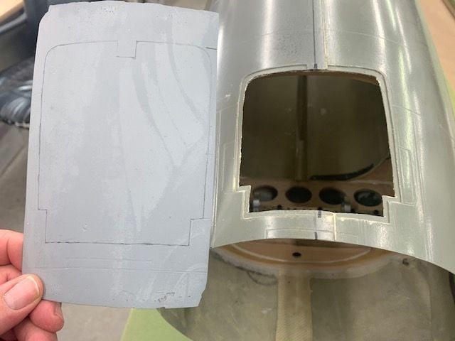
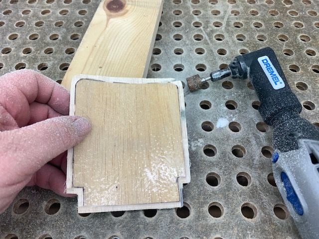
First step is to fit the door. My kit parts did not contain a door so Larry took a mold from his door and made a door for me out of laminated balsa and glass. First step is to trace the door outline on the blank.
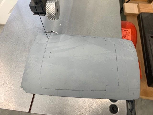
Rough cut out on jig saw
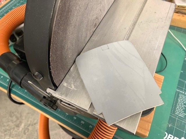
Sanding to rough shape

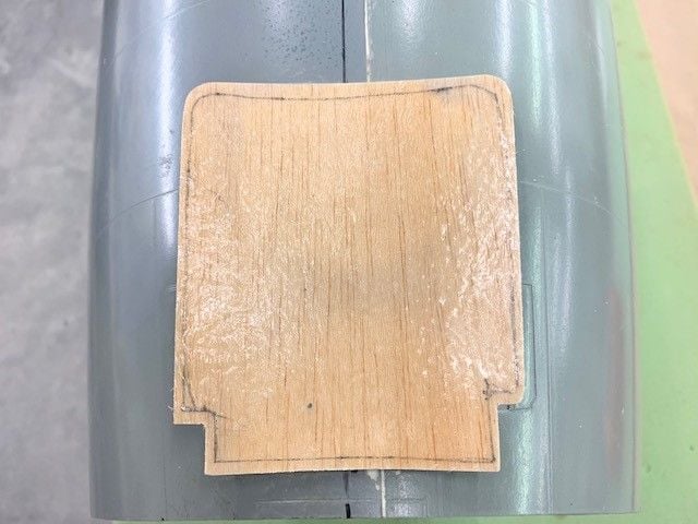
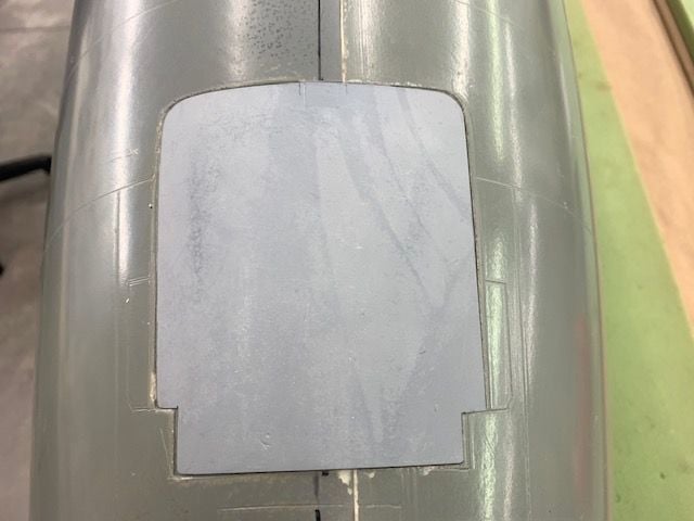
Fitting door to cut out in fuse by gently sanding to shape

Door fits into recessed area around cutout
Cut out area marked on bottom of door
Balsa and glass removed from bottom side around door

Door now fits flush with fuse skin
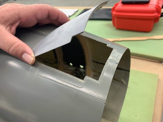
Simulated opening angle
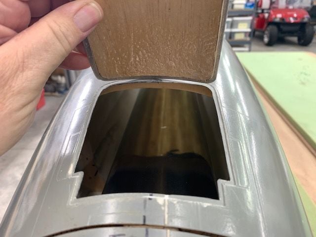
Chute tube and hardware have to fit in above the pipe and be protected from heat
I gave up on the gear doors for a while and started on something I thought I could get to work...the drag chute system. I had planned at first not to do one, but since Dave made such a cool Lua program to make it work with the Jeti radio I could not resist trying. My concept is to use the Skymaster 1/6 F-4 drag chute hardware and adapt it to the F-105 fuse. Issues are fitting the hardware in above the pipe and protecting it from heat.
First step is to fit the door. My kit parts did not contain a door so Larry took a mold from his door and made a door for me out of laminated balsa and glass. First step is to trace the door outline on the blank.
Rough cut out on jig saw
Sanding to rough shape
Fitting door to cut out in fuse by gently sanding to shape
Door fits into recessed area around cutout
Cut out area marked on bottom of door
Balsa and glass removed from bottom side around door
Door now fits flush with fuse skin
Simulated opening angle
Chute tube and hardware have to fit in above the pipe and be protected from heat
 02-21-2020, 08:50 AM
#527
I understand the massive frustration w/ the door geometry.......was wondering if off-set hinges instead of pin hinges would help the door miss the main door better........and give you a chance to use a mini servo to actuate it? Well...good luck! It's a blast watching you work on this!
02-21-2020, 04:07 PM
#529
Thread Starter
My Feedback: (20)
Yeah, I looked at several options for a servo. Linear servo too. Just no room in the gear mount area. I looked at inboard of the mount area in tire area also. Problem is how to make a linkage or push rod work because there is no room in the mount area. Also the attach horn on the door is a problem because of the same issue near the hinge line. I'm going to let Keith look at it a while and see if he can come up with something using his 3D print design skills. I'm just stuck now using the old fashion way.
Thanks for looking however,
Gary
Thanks for looking however,
Gary
02-21-2020, 04:31 PM
#530

you could just do it the old fashioned way with just main gear door cover and simple hatch cover for the little door. Certainly not optimum but it’s functional then reattack the outer door once you have some flights on her.
what about snaking a yellow nyrod along the gear well etc and actuate it via air cylinder or electric drive located somewhere inside the wheel well area.
what about snaking a yellow nyrod along the gear well etc and actuate it via air cylinder or electric drive located somewhere inside the wheel well area.

 02-21-2020, 06:14 PM
#533
Thread Starter
My Feedback: (20)
All great ideas.
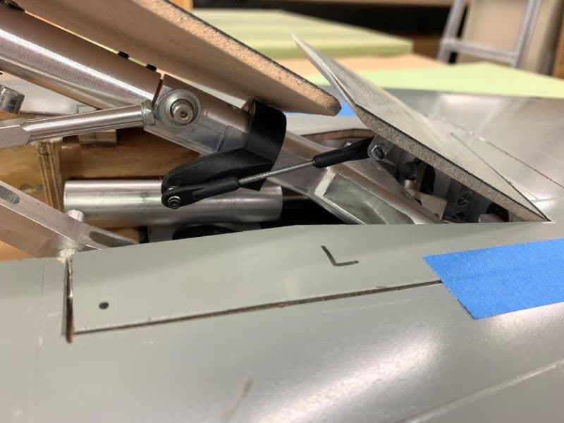
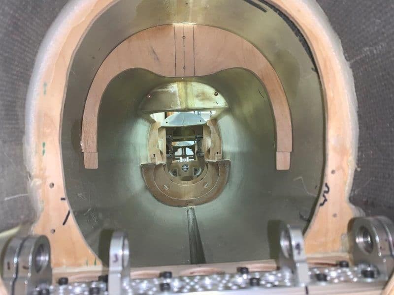
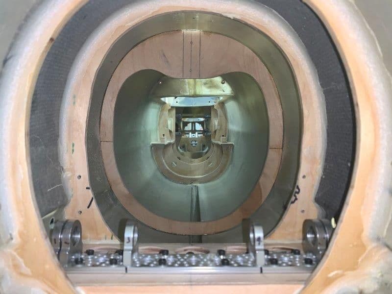
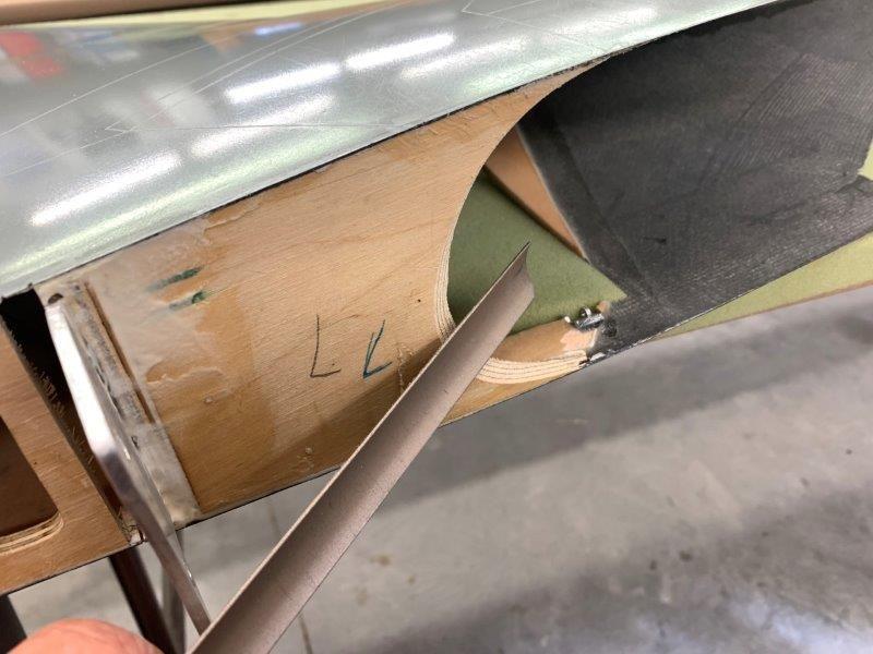
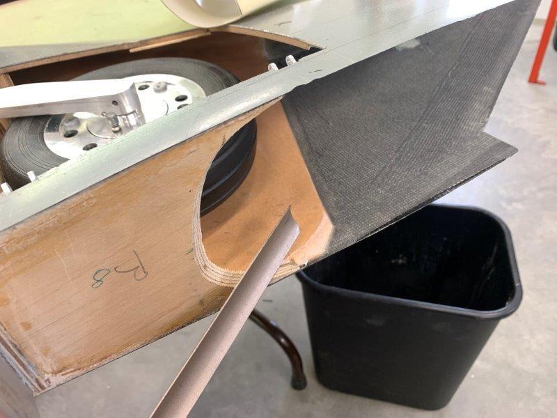
I did look at the nyrod idea. Problem is there is a tie bar (at bottom of the photo under the rotation link) that connects the over center lock to both air cylinders that moves back and forth under the main trunion. This cuts off the path for the nyrod or push rod from the bottom of the gear well. I couldn't figure out any way to make it work to the outer door. I did not want to cut a servo hole outboard of the gear mount. Even if I did I still have the problem of how to get the pushrod link through the gear mount to work the door.
The spring loaded door could work. I considered springs or rubber bands. After I put the angle faring on the outer door edge that forces the main door under the outer door it was possible. So far that has the best chance if I can't get a link to work.
Keep the ideas coming. I really appreciate the suggestions. I'm sure there is a way to make it work.
Thanks,
Gary
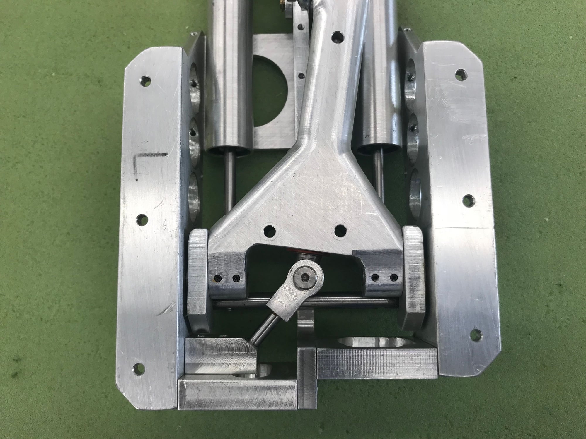
Last edited by Viper1GJ; 02-21-2020 at 06:23 PM.
02-21-2020, 06:30 PM
#534

Ignore Buck, he does not suffer from the gear door sickness, I can tell you are a fellow sufferer. I feel your pain.
How about getting rid of the rigid linkage completely.... let the corner of the main strut door just push the little outer door open (it looks like the air loads will pull it open too).
You close the outer door with a cable linked to the strut. When the gear goes up, the cable pulls it closed. Magnets help it at the end if needed. In the gear down position, there should be enough slack in the cable to let the door open as far as needed.
02-21-2020, 06:41 PM
#535
Thread Starter
My Feedback: (20)
How about getting rid of the rigid linkage completely.... let the corner of the main strut door just push the little outer door open (it looks like the air loads will pull it open too). You close the outer door with a cable linked to the strut. When the gear goes up, the cable pulls it closed. Magnets help it at the end if needed. In the gear down position, there should be enough slack in the cable to let the door open as far as needed.
Thanks,
Gary
02-24-2020, 03:01 PM
#537

maybe this video of my simple gear door closing mechanism can give you some ideas. The spring is a fine extension spring strung between the two doors. It works fast and reliably for years. The video says Habu, but that's just where this idea of mine was first used. This is s TopRC F9F Cougar.
Last edited by Pull Up Now!; 02-24-2020 at 09:25 PM.
02-24-2020, 06:30 PM
#538
Thread Starter
My Feedback: (20)
Took a long weekend last week to go fly the turbine foamie fleet and Havoc at Flying Tigers Chili Fly in Lake City, SC.
I also took the F-105 wings and picked lots of brains for gear door ideas. Nyrods and springs were discussed a lot. I also called Phil Clark at Fighteraces in the UK who built one of these kits. He said it was a lot of trial and error but he found a hard link combination that worked. Keith took one of the gear home to 3D print a linkage bracket that may help. More to come on the gear doors...
Foamies and Havoc flew great, perfect weather Sat and Sunday after the flooding rain Thursday and arctic hurricane Friday!
05-21-2020, 05:19 PM
#539
Thread Starter
My Feedback: (20)
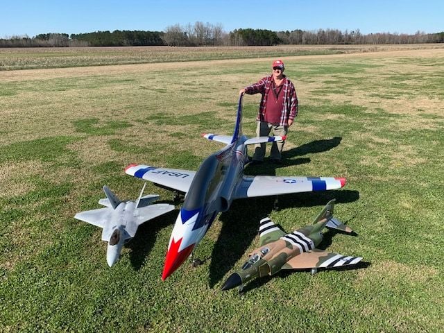
Its been 3 months since the last post. After the trip to Lake City mentioned above my friend Keith produced a 3D printed bracket and arm for the main gear strut that operates the outer door very well. Also I used 2-56 ball joints instead of 4-40. Now I have both outer doors working well and the main gear door just clears the outer door as the gear swings up and down. This was one of the most frustrating tasks so far and just getting some help from Keith solved it perfectly. Thanks Keith!
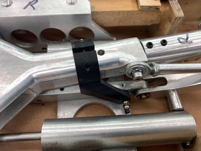
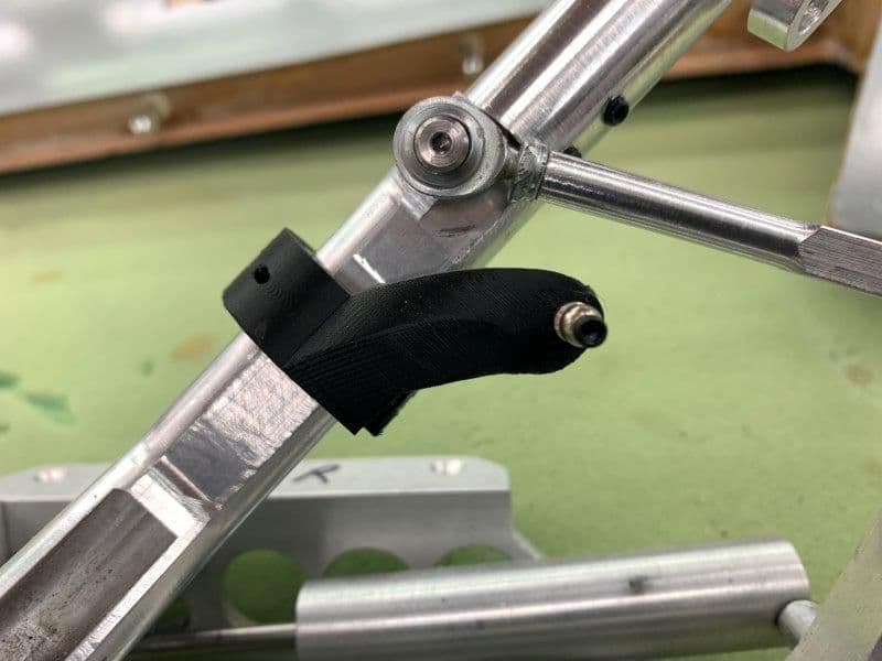
New bracket arm allows the ball joint to be nearly at the bottom of the gear well and allows the required range of motion. I could never get this to work with the wood arms I tried to make.
Bracket bolts to the strut
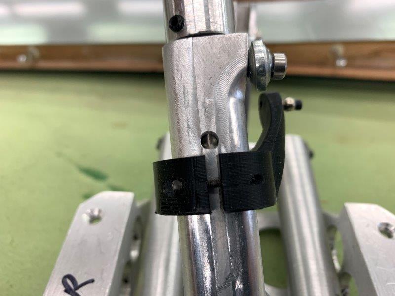
I need to learn how to make this stuff with a 3D printer
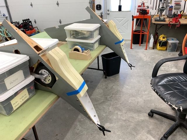
Main and outer doors maintain clearance as gear retracts
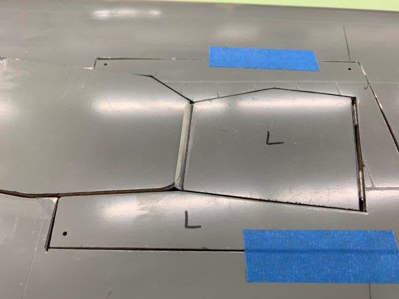
All closed up. Doors flush on trailing edge

Nice close fit here.
Only problem is the gap on the leading edge of the main door. I'm going to ignore this for now and deal with it later after I find out how much lower i will hang when the weight of the strut and wheel are pulling it down.
New bracket arm allows the ball joint to be nearly at the bottom of the gear well and allows the required range of motion. I could never get this to work with the wood arms I tried to make.
Bracket bolts to the strut
I need to learn how to make this stuff with a 3D printer
Main and outer doors maintain clearance as gear retracts
All closed up. Doors flush on trailing edge
Nice close fit here.
Only problem is the gap on the leading edge of the main door. I'm going to ignore this for now and deal with it later after I find out how much lower i will hang when the weight of the strut and wheel are pulling it down.
Last edited by Viper1GJ; 05-21-2020 at 05:54 PM.
05-21-2020, 05:26 PM
#540
Thread Starter
My Feedback: (20)
Nothing was accomplished during March and April. I was in day care jail with a 3yr old grandson helper every day. He was no problem but just 100% full time so not much F-105 work done. Day care jail ended last week and I finally got back to the 105 project. I needed something easy to do to make some visible progress to get motivated again. So I decided to work on the vertical fin former and wing air intakes.
05-21-2020, 05:37 PM
#541
Thread Starter
My Feedback: (20)
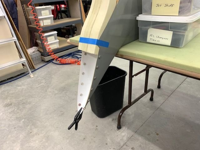
A year ago I discovered that the fin former would not fit in the fuse with the pipe mount and stab mount formers in place so I had to cut it in half to get it in.
Scab patch tabs fabricated to align the bottom and top half of the former
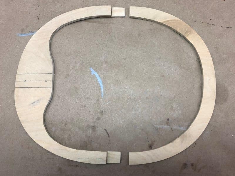
Tabs glued to top half on each side
Dry fit of bottom half of former

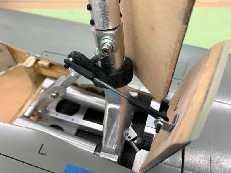
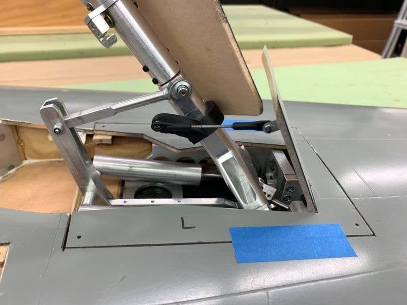
Top part of former aligned in position by clamping to the vertical fin aluminum spar
Top half tack glued in place with medium CA
Bottom half clamped to alignment tabs and tack glued in with medium CA
Edges sanded smooth at joints. Ready for epoxy to fuse.
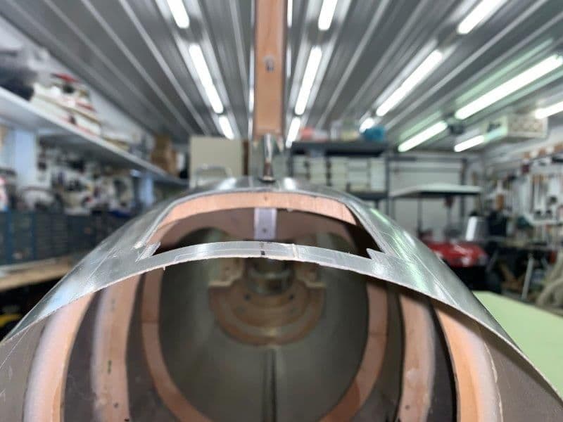
Vertical fin in place aligned with the former. The vertical alignment will be set with a laser level for final assembly. Finally something simple that worked!
Scab patch tabs fabricated to align the bottom and top half of the former
Tabs glued to top half on each side
Dry fit of bottom half of former
Top part of former aligned in position by clamping to the vertical fin aluminum spar
Top half tack glued in place with medium CA
Bottom half clamped to alignment tabs and tack glued in with medium CA
Edges sanded smooth at joints. Ready for epoxy to fuse.
Vertical fin in place aligned with the former. The vertical alignment will be set with a laser level for final assembly. Finally something simple that worked!
05-21-2020, 05:50 PM
#542
Thread Starter
My Feedback: (20)
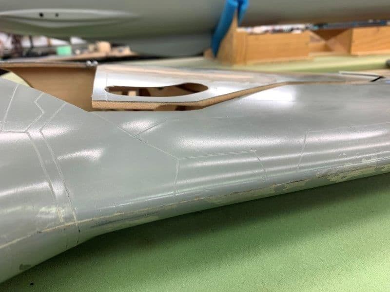
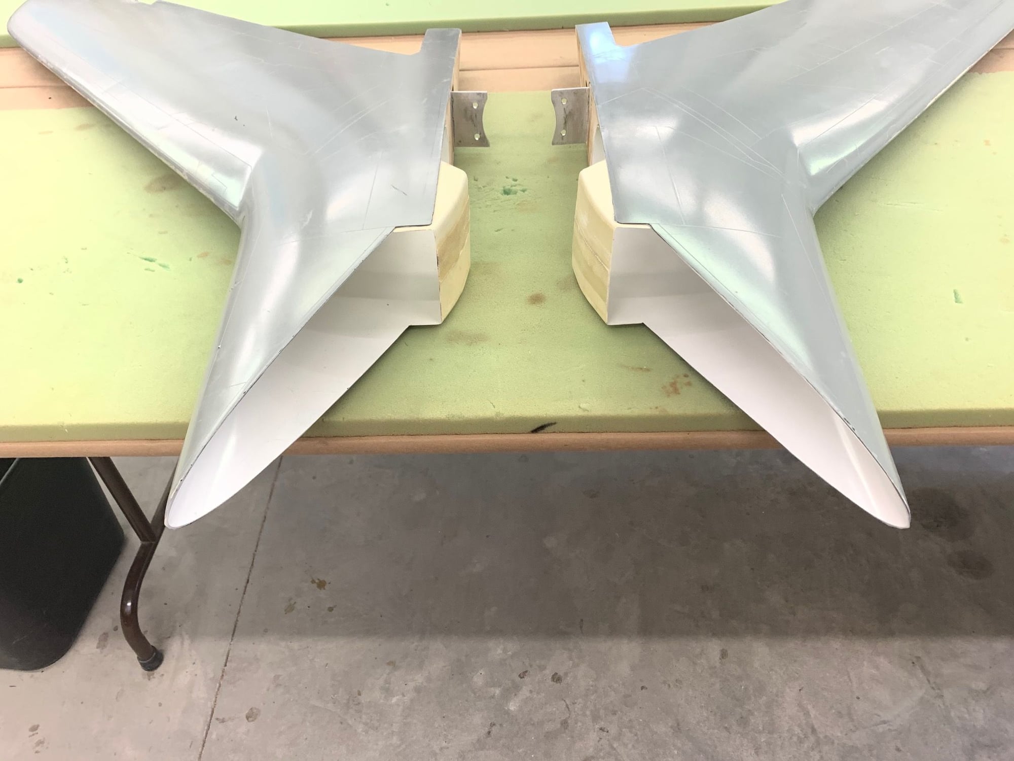
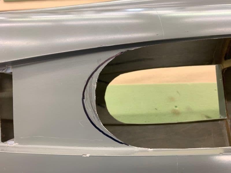
Fitting wing air intakes.
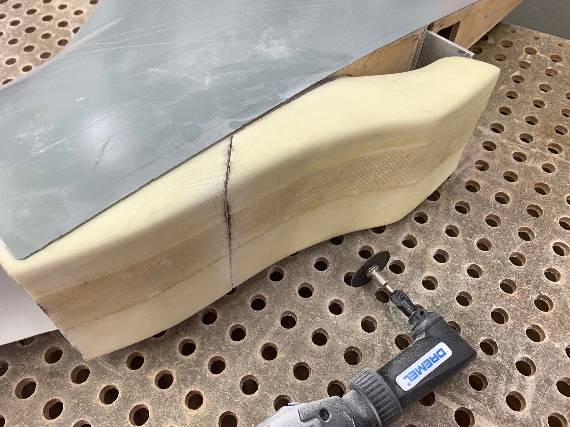
Intakes were designed to extend deep inside fuse to a single duct that fed the air directly to the turbine. Since my wing spar now blocks this duct I will cut the wing intakes short just to funnel air into the fuse. The turbine will suck it up from there.
First task is to cut the intakes shorter to clear the wing spar and seat into the root rib
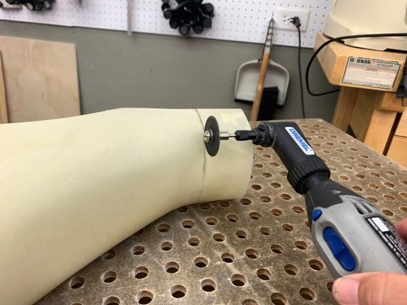
Cutting on down draft table
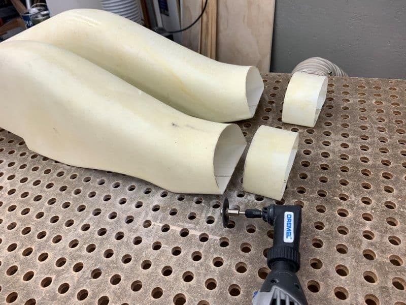
Rough cuts done
1/4" ply root rib opening shaped ot accept the intake a the proper angle.
Perma grit dremel drum grinder and perma grit convex curve sanding tool really helped make cutting the angle on the 1/4" ply easier
Intakes were designed to extend deep inside fuse to a single duct that fed the air directly to the turbine. Since my wing spar now blocks this duct I will cut the wing intakes short just to funnel air into the fuse. The turbine will suck it up from there.
First task is to cut the intakes shorter to clear the wing spar and seat into the root rib
Cutting on down draft table
Rough cuts done
1/4" ply root rib opening shaped ot accept the intake a the proper angle.
Perma grit dremel drum grinder and perma grit convex curve sanding tool really helped make cutting the angle on the 1/4" ply easier
The following users liked this post:
[email protected] (05-21-2020)

The following users liked this post:
[email protected] (05-21-2020)

 05-22-2020, 05:52 PM
#545
Thread Starter
My Feedback: (20)
Thanks guys. I'm getting motivated again to get this thing done.
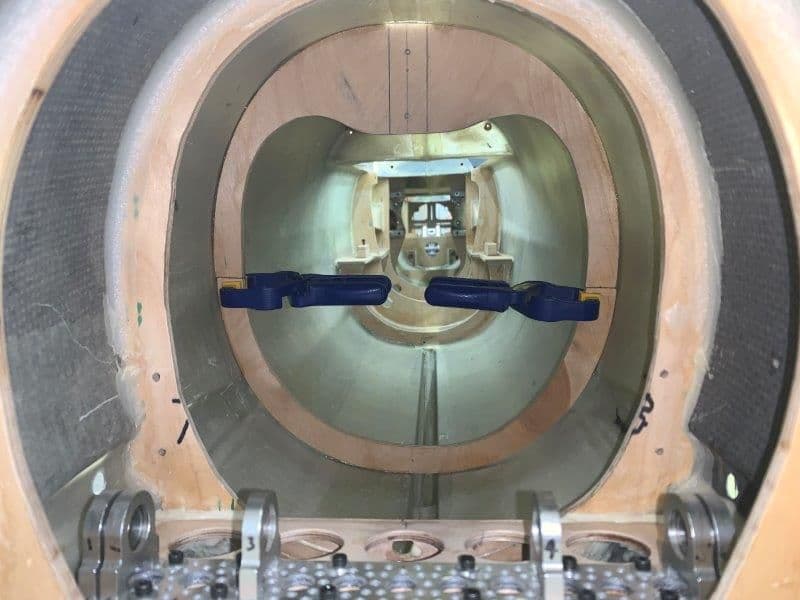
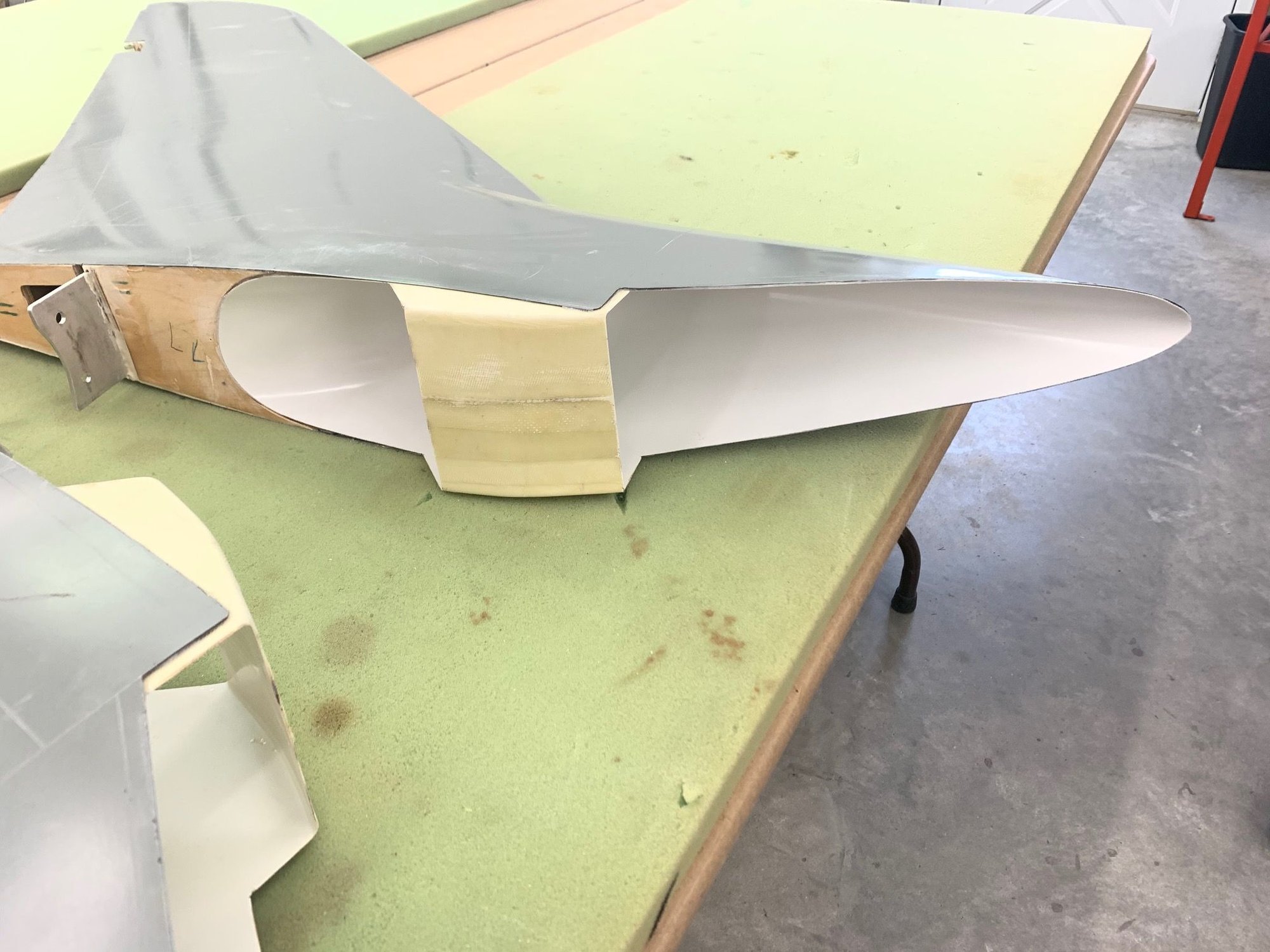
Glued in the intakes to the wings today. Used Six10 epoxy.
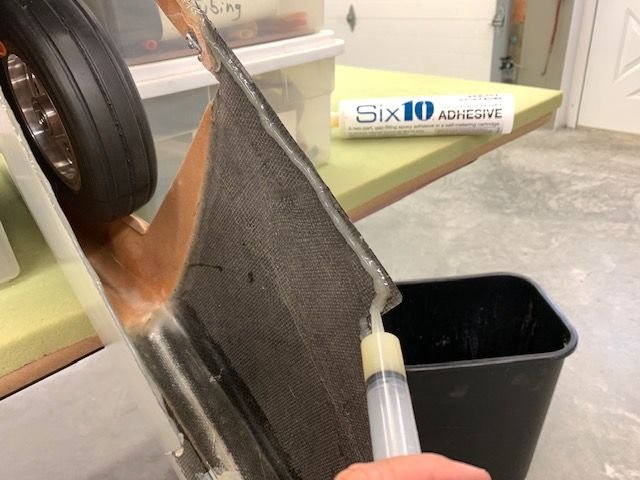
After dry fitting I applied epoxy with syringe to the edge of the wing root intakes.
I set the wings on the leading edge so as not to distort the shape of the intake during the gluing process. When laying on the top or bottom the intake slightly flattens from the weight. Then applied the epoxy to the edges.

Intakes were taped and clamped on. Magnets worked as perfect clamps on the edges.
Other side done.
Waiting for epoxy cure.
Glued in the intakes to the wings today. Used Six10 epoxy.
After dry fitting I applied epoxy with syringe to the edge of the wing root intakes.
I set the wings on the leading edge so as not to distort the shape of the intake during the gluing process. When laying on the top or bottom the intake slightly flattens from the weight. Then applied the epoxy to the edges.
Intakes were taped and clamped on. Magnets worked as perfect clamps on the edges.
Other side done.
Waiting for epoxy cure.
 05-24-2020, 04:44 PM
#547
Thread Starter
My Feedback: (20)
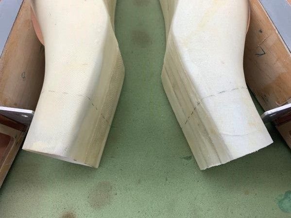
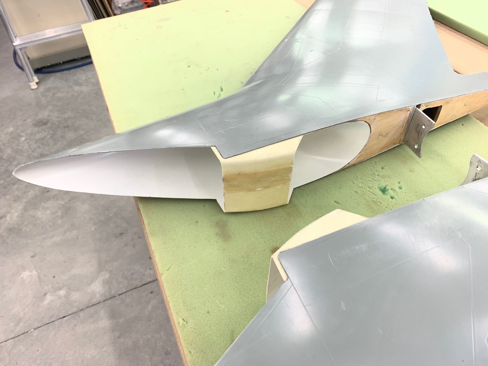
Wing intakes trimmed and cut to clear fuel tank
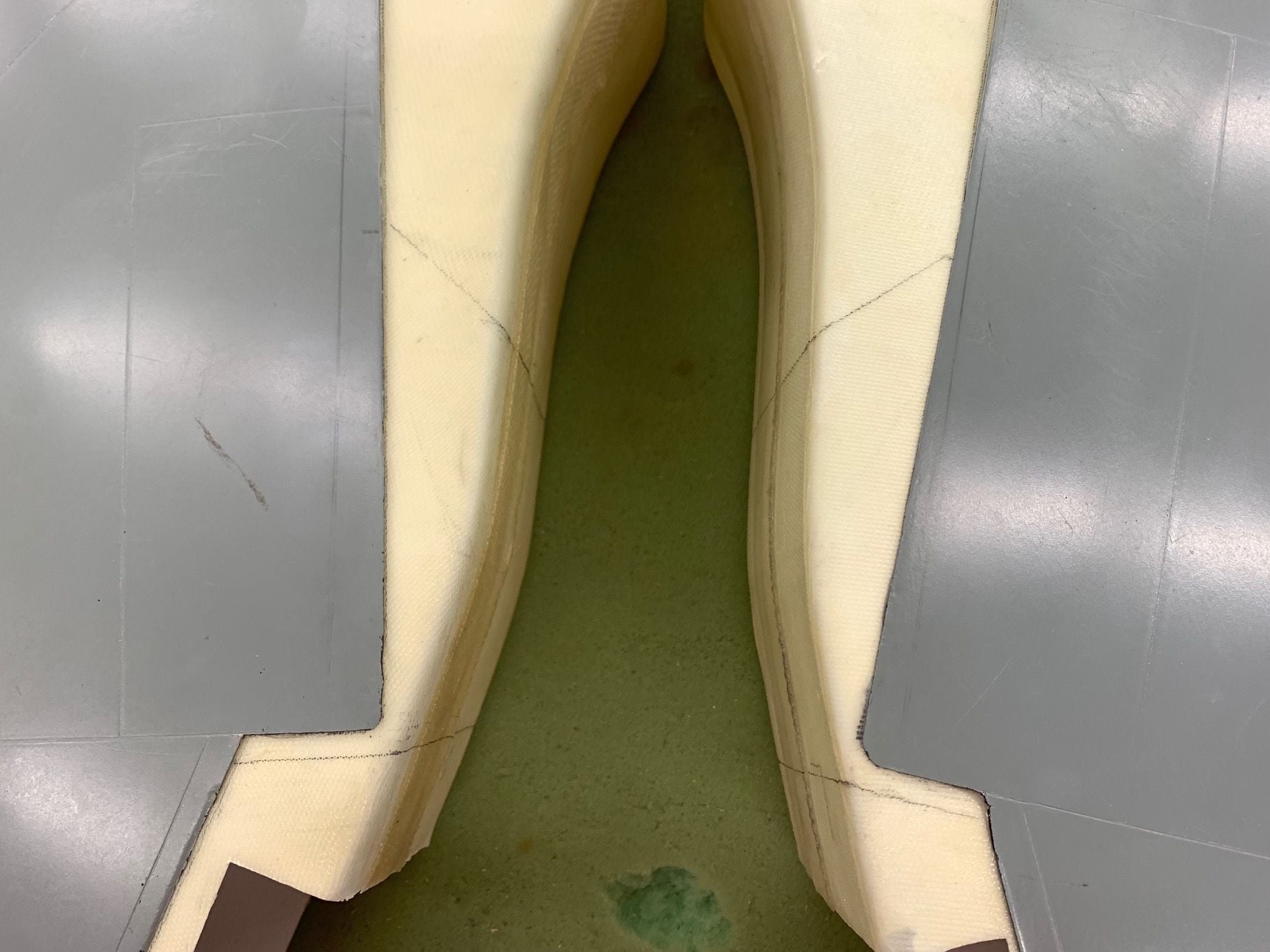
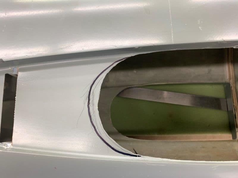
Cut lines marked. Intakes were made to funnel air to a center tube but my new wing spar prevents that so I will cut them short. The trick is to make them narrow enough to not take up fuel tank space.
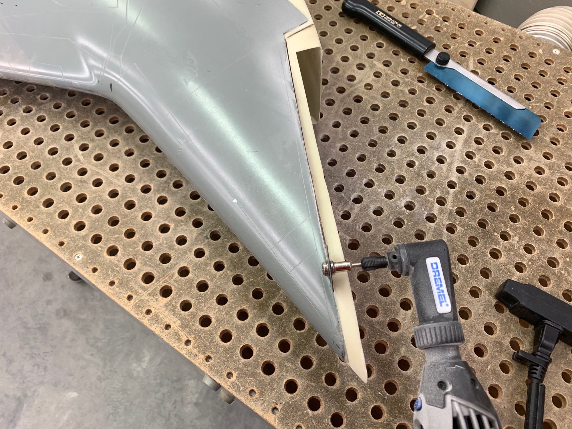
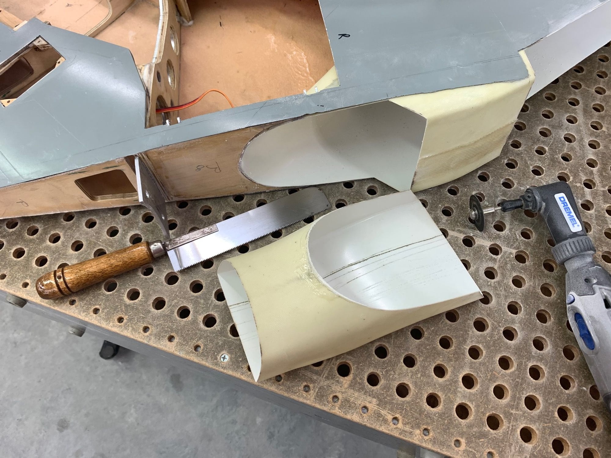
Dremel disc used to make rough cuts
Cut at leading edge of intake made slightly over size to fit into fuse gap.
Cut off removed
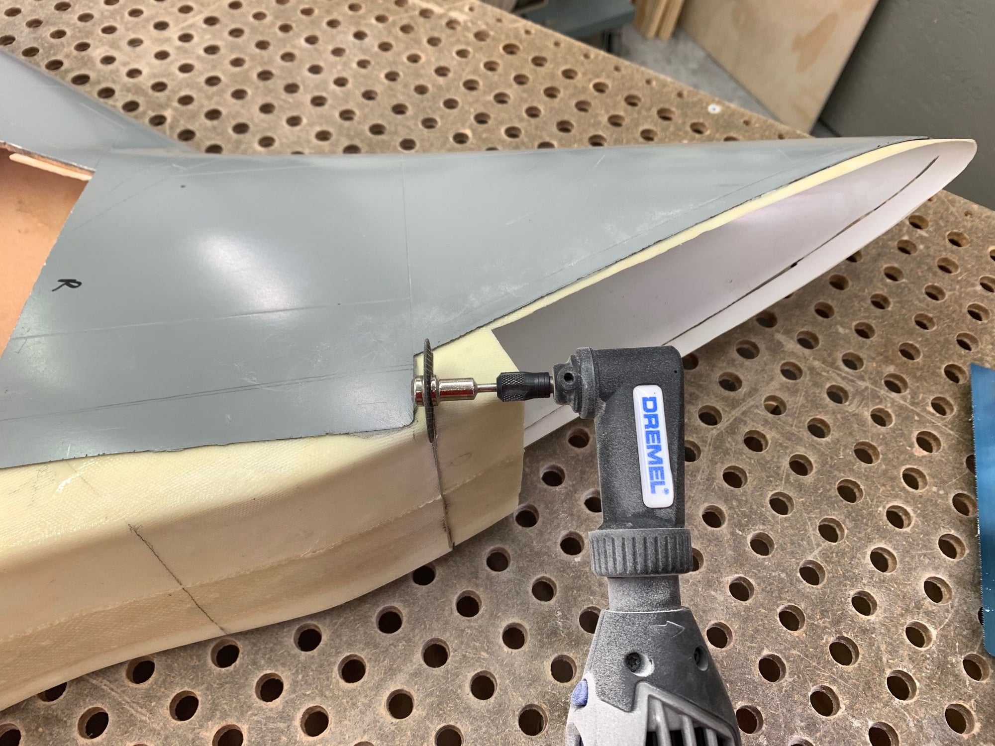
Aft cut made to shorten and reduce width into the fuel tank area
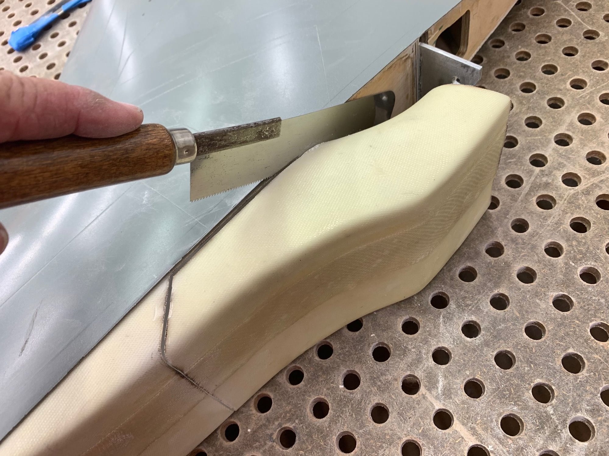
Flush cut saw used to make final cut
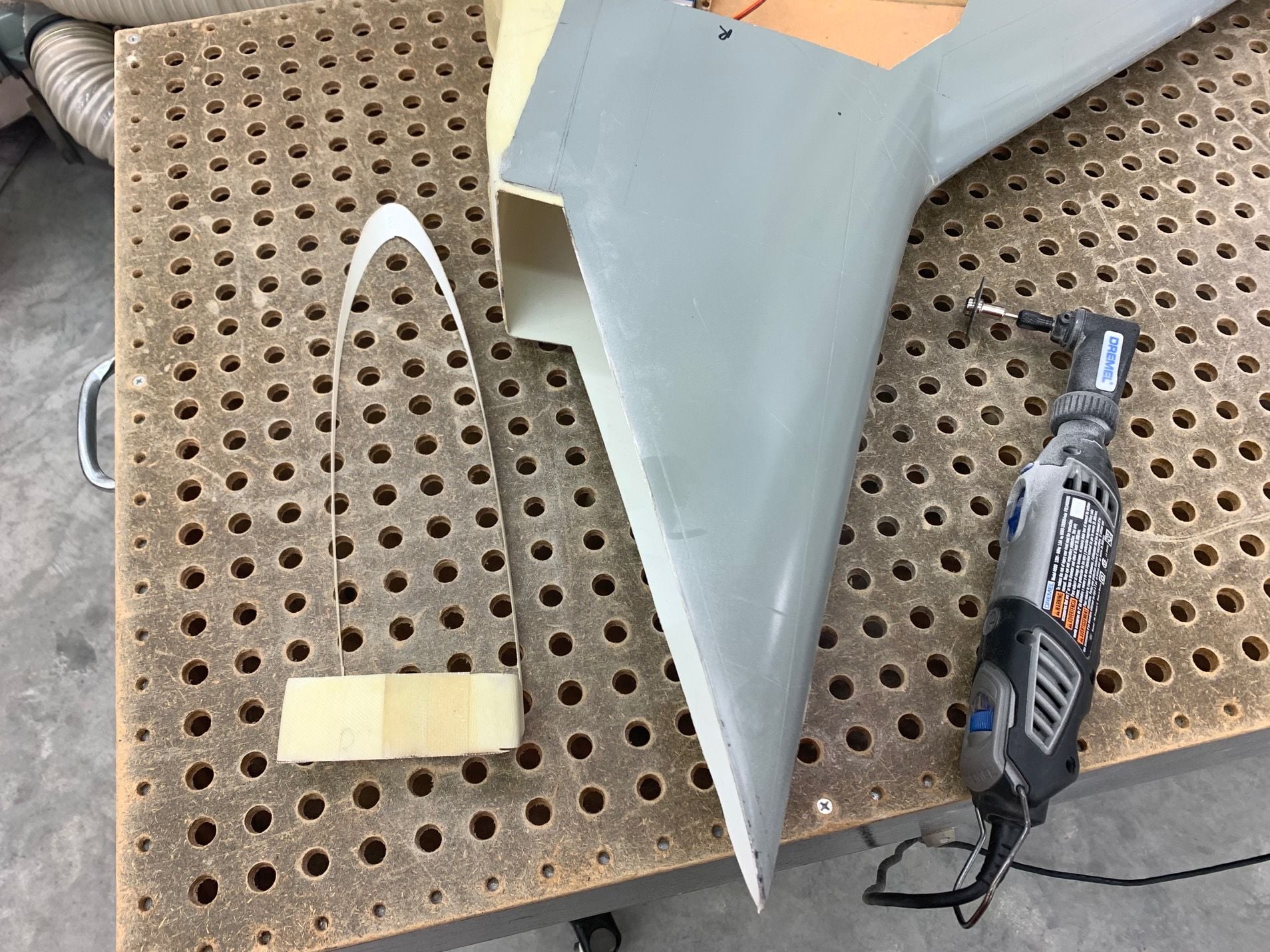
Done
Edges cleaned up and sanded
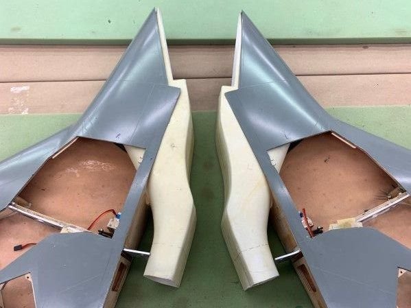
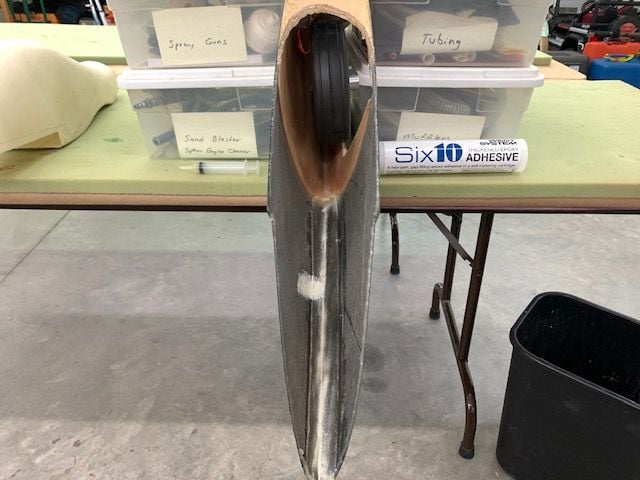
Front view
Right side
If I were a air molecule I could get thru here!
Cut lines marked. Intakes were made to funnel air to a center tube but my new wing spar prevents that so I will cut them short. The trick is to make them narrow enough to not take up fuel tank space.
Dremel disc used to make rough cuts
Cut at leading edge of intake made slightly over size to fit into fuse gap.
Cut off removed
Aft cut made to shorten and reduce width into the fuel tank area
Flush cut saw used to make final cut
Done
Edges cleaned up and sanded
Front view
Right side
If I were a air molecule I could get thru here!
05-25-2020, 05:20 PM
#548
Thread Starter
My Feedback: (20)
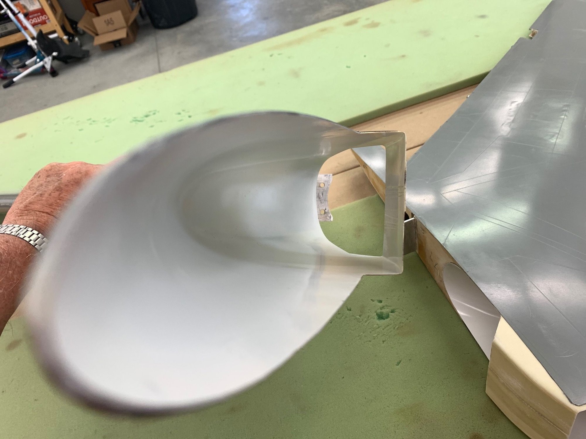
Fitting wing intakes to fuse and fuel tank planning

Took some sanding intakes to get them to fit the fuse wing openings
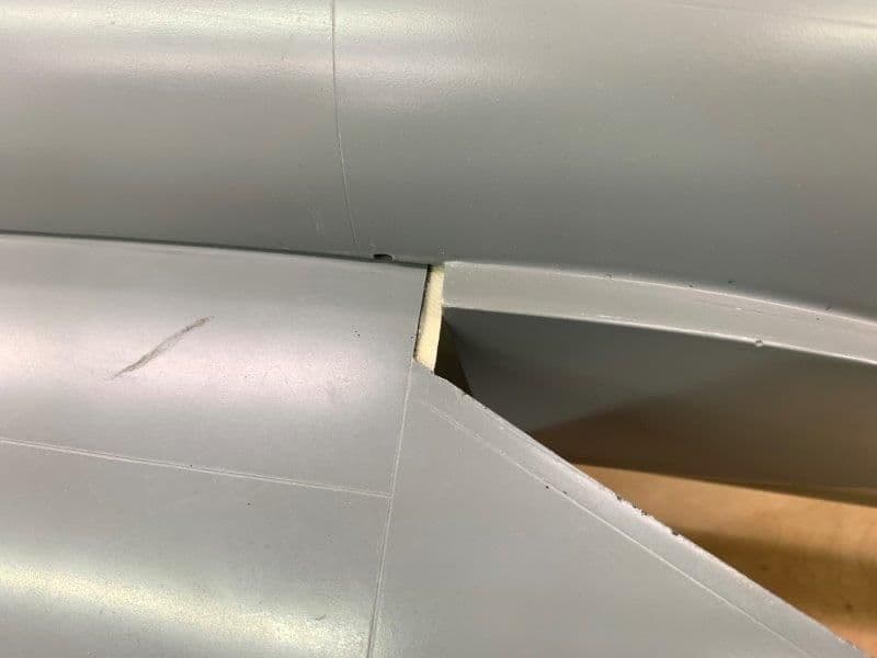
Top right side has about 5mm gap that has to be filled
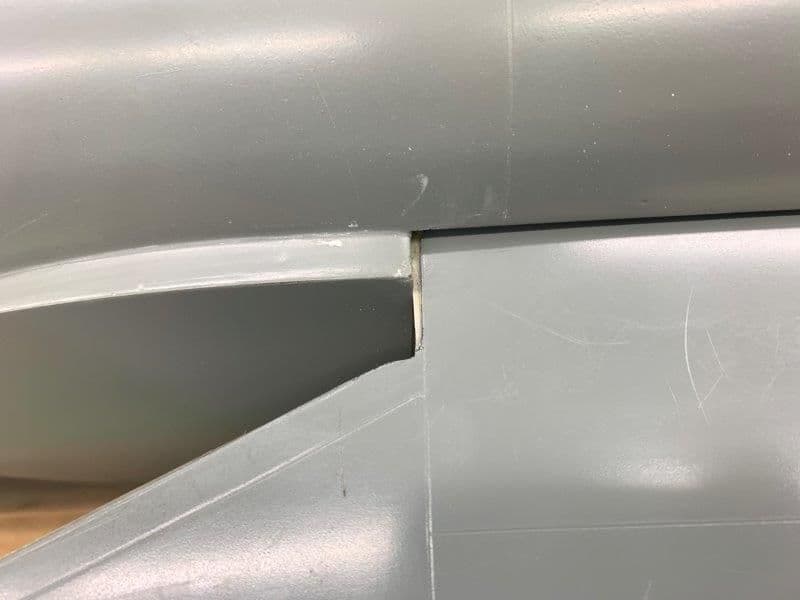
Left side about 3mm gap
Fuse opening marked and trimmed to fit wing opening
Same on the other side.

Dremel perma grit grinder used to trim intake holes
Both sides done
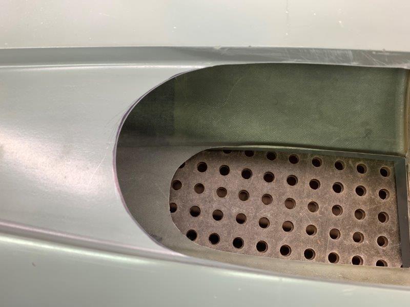
I was frustrated to see for some reason the left intake got set on an angle that I did not see before now. So now it is a little off and there is nothing I can do about it. The fix is to get over it. I think the air molecules will find their way to the turbine and it wont be seen from the outside.
Fuel tank planning. The tanks that came with the jet are designed to fit between the intakes and forward of the central duct that I am not using. This puts the fuel way forward and the triangle shape of the tank has most of the volume and weight forward. They are flat and don't effectively use the available fuse volume. Each tank holds only 4.5L. One is not enough and both are too much with the fuel too far forward. So I plan to make a new tank.
The new tank has to fit between the two formers. The CG is on the wing spar at the rear former. That puts all the fuel ahead of the CG. The tank needs to be as far aft as possible and have as much volume toward the rear as possible. However it has to allow air to flow from the intakes to the turbine so it will be tapered some toward the rear to allow air to flow under the spar. The tank has to fit between the wing intakes, fit through the cockpit opening, and hold max volume to feed the K-320. So making a tank will be the next challenge.
Took some sanding intakes to get them to fit the fuse wing openings
Top right side has about 5mm gap that has to be filled
Left side about 3mm gap
Fuse opening marked and trimmed to fit wing opening
Same on the other side.
Dremel perma grit grinder used to trim intake holes
Both sides done
I was frustrated to see for some reason the left intake got set on an angle that I did not see before now. So now it is a little off and there is nothing I can do about it. The fix is to get over it. I think the air molecules will find their way to the turbine and it wont be seen from the outside.
Fuel tank planning. The tanks that came with the jet are designed to fit between the intakes and forward of the central duct that I am not using. This puts the fuel way forward and the triangle shape of the tank has most of the volume and weight forward. They are flat and don't effectively use the available fuse volume. Each tank holds only 4.5L. One is not enough and both are too much with the fuel too far forward. So I plan to make a new tank.
The new tank has to fit between the two formers. The CG is on the wing spar at the rear former. That puts all the fuel ahead of the CG. The tank needs to be as far aft as possible and have as much volume toward the rear as possible. However it has to allow air to flow from the intakes to the turbine so it will be tapered some toward the rear to allow air to flow under the spar. The tank has to fit between the wing intakes, fit through the cockpit opening, and hold max volume to feed the K-320. So making a tank will be the next challenge.
Last edited by Viper1GJ; 05-25-2020 at 05:24 PM.
05-25-2020, 05:39 PM
#549
Thread Starter
My Feedback: (20)
Fuel tank prep
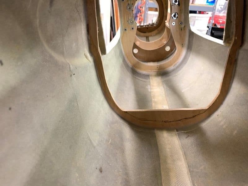
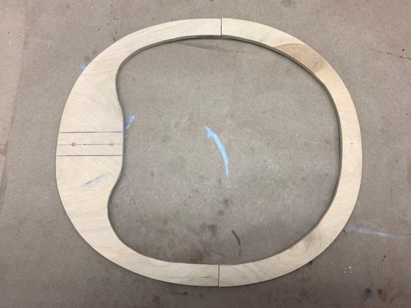
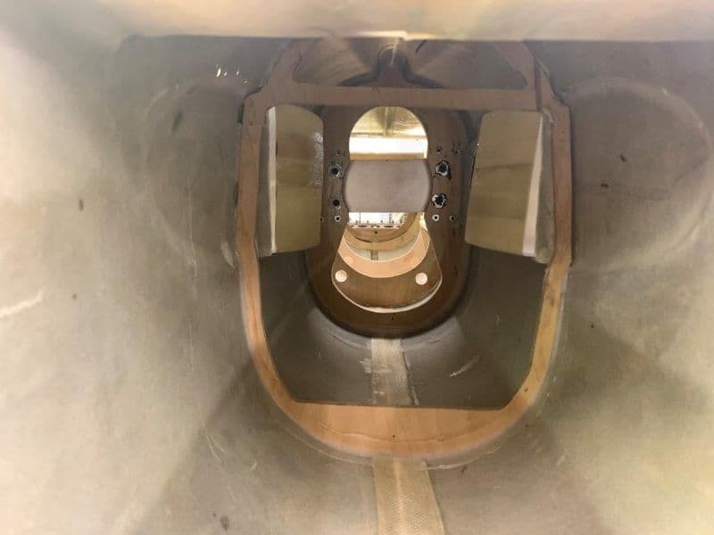
The flat bottom on the former was for the floor for the flat tanks that were way forward of the CG

I freehanded a curved cut with a dremel router bit.
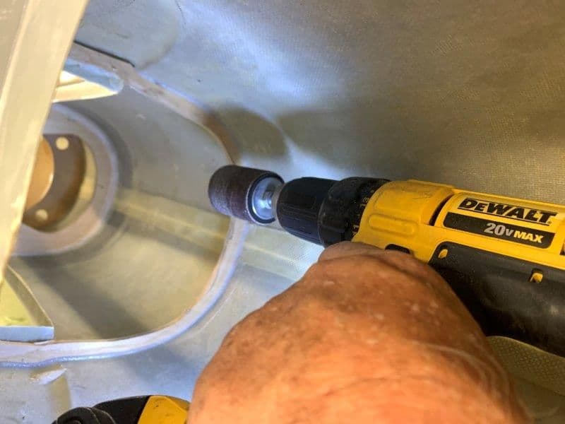
Smoothed cut with drum sander
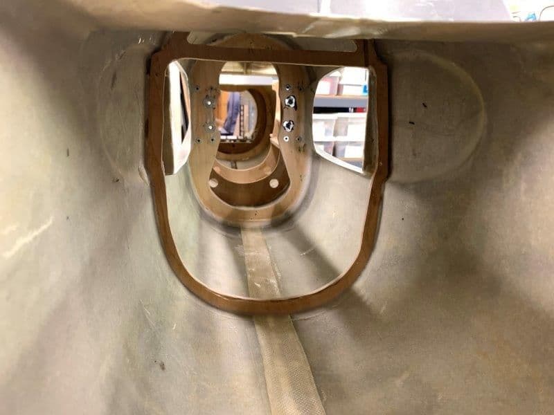
Now I can get a curved bottom tank through the former.

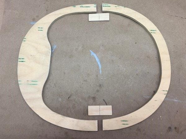
First draft of a template for the tank profile
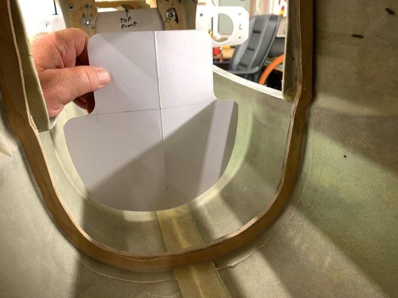
First draft template needs some adjustments but its just to visualize the front shape of the planned tank. The top bump could be higher inside the fuse but it would not go through the cockpit opening. Maybe I could use a bottom and top tank and feed in series to get more volume. Still thinking...
The flat bottom on the former was for the floor for the flat tanks that were way forward of the CG
I freehanded a curved cut with a dremel router bit.
Smoothed cut with drum sander
Now I can get a curved bottom tank through the former.
First draft of a template for the tank profile
First draft template needs some adjustments but its just to visualize the front shape of the planned tank. The top bump could be higher inside the fuse but it would not go through the cockpit opening. Maybe I could use a bottom and top tank and feed in series to get more volume. Still thinking...
