


1/6 F-105 Build Thread
 01-26-2020, 06:52 PM
#501

Thread Starter
My Feedback: (20)
The doors popped off the struts easily and Vaselene residue cleaned with lacquer thinner.
The hysol gave a set angle to work with when filling in the holes.
First step was to cover the axle holes with clear packing tape to protect the threads. Then Vaseline reapplied to the strut
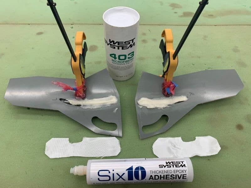
Next the doors were clamped to the struts. The clamp pads were protected with Saran plastic wrap. A paste of Six10 epoxy and micro balloons was laid it on top of the struts. The 6 oz glass cloth was cut and ready to wet out.
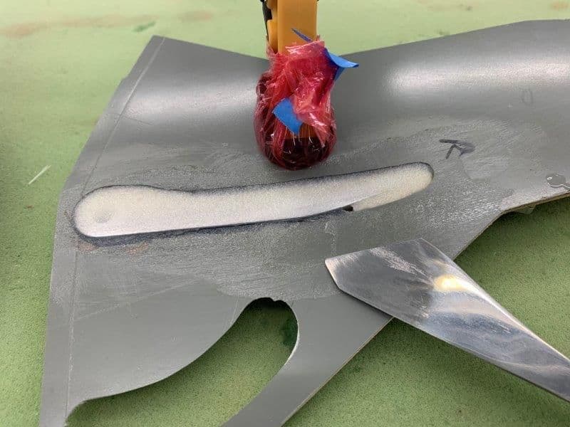
Straight edge use to scrape off the excess paste level with door surface
The glass cloth was wet out with West epoxy and laid in place. Excess was blotted off with paper towel squares and tissues.
The hysol gave a set angle to work with when filling in the holes.
First step was to cover the axle holes with clear packing tape to protect the threads. Then Vaseline reapplied to the strut
Next the doors were clamped to the struts. The clamp pads were protected with Saran plastic wrap. A paste of Six10 epoxy and micro balloons was laid it on top of the struts. The 6 oz glass cloth was cut and ready to wet out.
Straight edge use to scrape off the excess paste level with door surface
The glass cloth was wet out with West epoxy and laid in place. Excess was blotted off with paper towel squares and tissues.
Last edited by Viper1GJ; 01-26-2020 at 06:56 PM.
 01-26-2020, 07:05 PM
#502
Thread Starter
My Feedback: (20)
Setting the gear cover plates
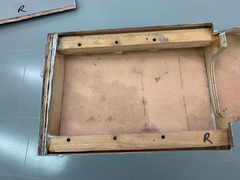
The 1/4" plywood rib outboard of the gear mounts was too high to allow the gear cover plate to be flush with wing skin. It had to be ground down about 1/8"
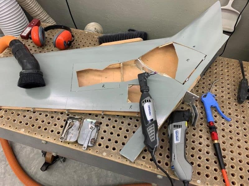
Assortment of tools needed to make the cut.
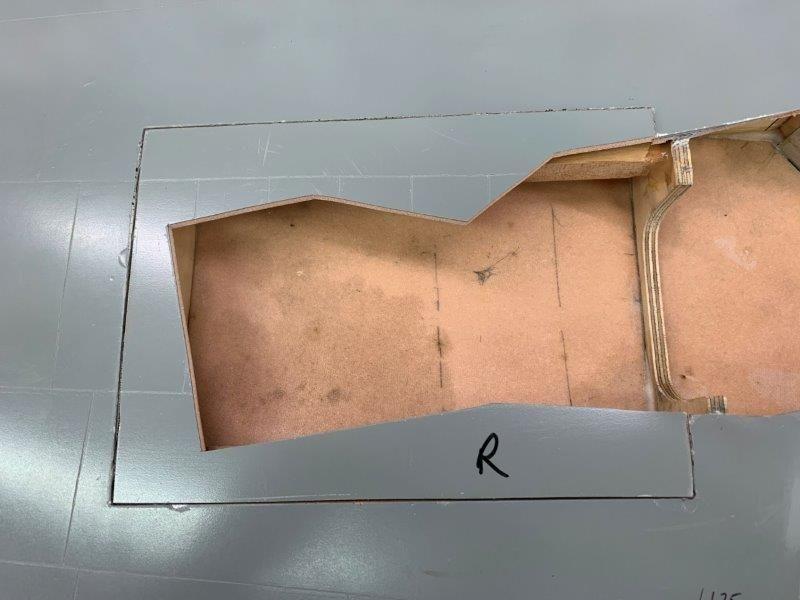
Gear plate in place
Gear installed required a relief cut to allow plate to sit flush with wing skin.
Left side done
Relief cuts needed on right side
Right side done. Next are screw mounts for cover plate. The slog continues...
The 1/4" plywood rib outboard of the gear mounts was too high to allow the gear cover plate to be flush with wing skin. It had to be ground down about 1/8"
Assortment of tools needed to make the cut.
Gear plate in place
Gear installed required a relief cut to allow plate to sit flush with wing skin.
Left side done
Relief cuts needed on right side
Right side done. Next are screw mounts for cover plate. The slog continues...
01-26-2020, 08:20 PM
#503

This may have been what Matt was already alluding to, but keep in mind the compression of your struts on touchdown. The way you�ve cut out relief for the tires is great but only works in the extended strut position. Make sure the tires don�t contact the doors through the full travel of the struts.
01-27-2020, 10:37 AM
#504

This may have been what Matt was already alluding to, but keep in mind the compression of your struts on touchdown. The way you�ve cut out relief for the tires is great but only works in the extended strut position. Make sure the tires don�t contact the doors through the full travel of the struts.
Bob
01-27-2020, 06:01 PM
#506
Thread Starter
My Feedback: (20)
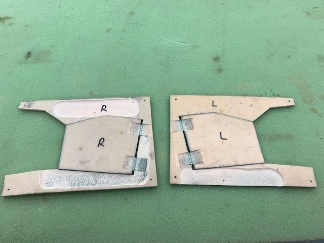
Gear doors fitting to main gear struts
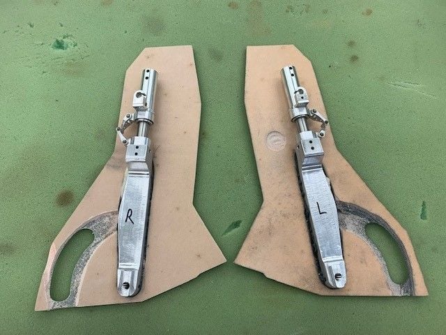
After seeing Auburn's post above I realized I did not even considered movement of the shock strut at all. I worried till I went to bed. How dumb could I be? I never even thought about it. So first thing this morning I checked. No problem, the door and wheels are fixed to the strut and do not move relative to each other. I got lucky. This comes under the old fighter pilot axiom of "I'd rather be lucky than good on any day". Well I got lucky on this one.
The other problem seen by Matt I did not think about either. Yes the gear has enough slop in the up lock that it hangs down about 5-6mm at wheel end when the gear is on the bottom of the wing and gravity pulls it out. This causes the door to be 5-6mm below the wing skin when retracted. I really don't have a fix. There is no more room to raise the trunnion and mounts inside the wing structure. The struts are now recessed into the door the full thickness of the door. The only thing I can think of is a secondary gear up lock of some type that actually holds the strut fully up in the wing. I can only imagine the problems with that. So for now I'm going to pretend it doesn't happen and press on with basic construction. Not sure how to fix this.
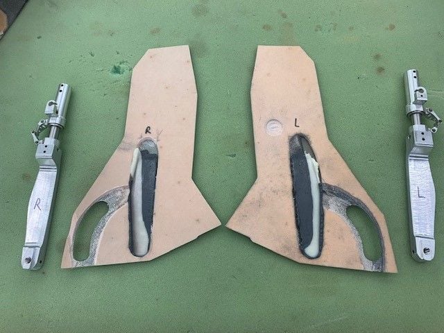
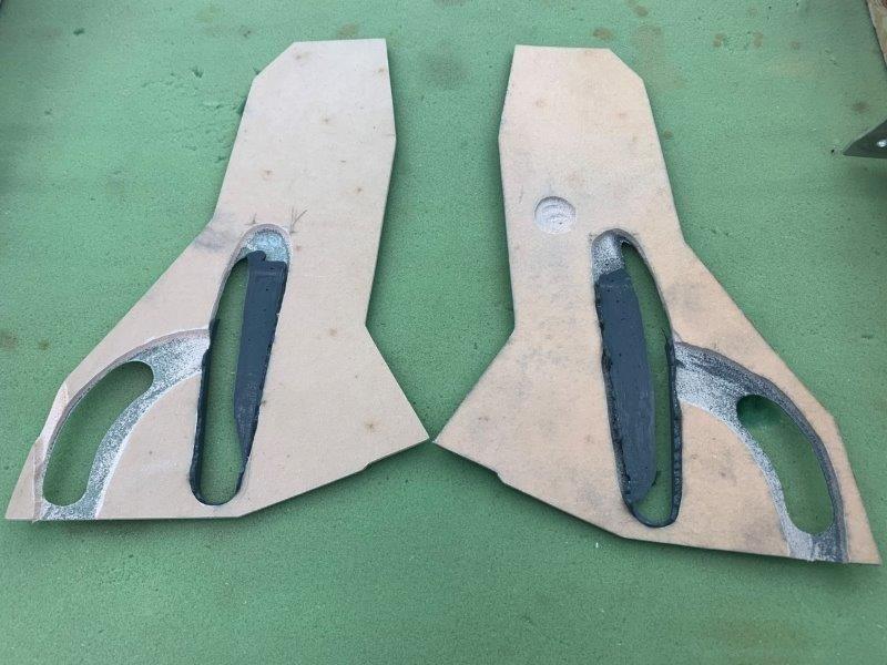
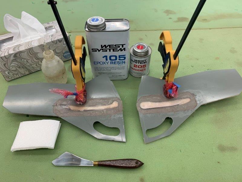
Doors popped out of struts showing the epoxy mounting surface.
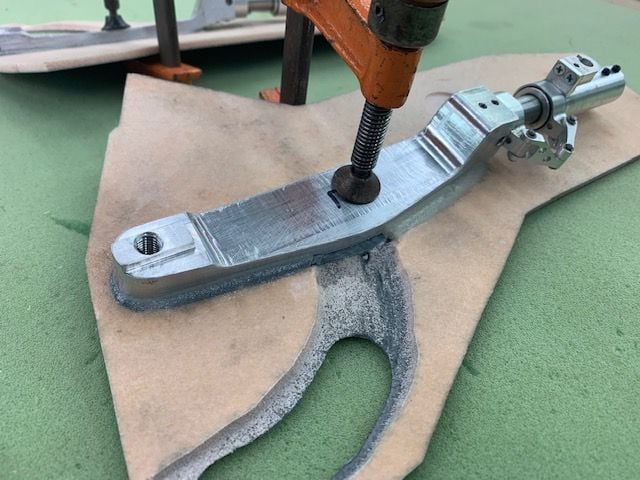
Six-Ten and micro balloon paste use to fill void in door above the strut and make a small fillet around the strut to hold it in place. Clamps will be used to fasten the door to the strut.

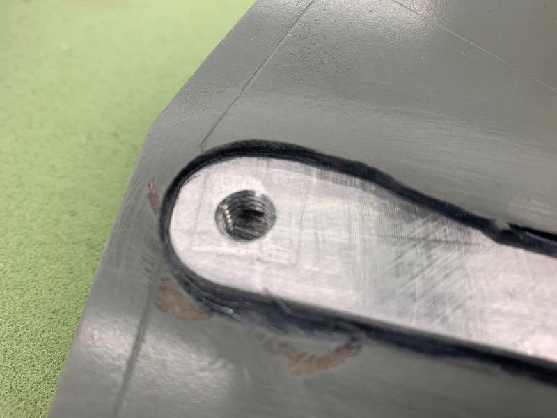
Epoxy fillet on right side strut
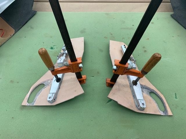
Ready for cure. The tire holes will be fixed next.
After seeing Auburn's post above I realized I did not even considered movement of the shock strut at all. I worried till I went to bed. How dumb could I be? I never even thought about it. So first thing this morning I checked. No problem, the door and wheels are fixed to the strut and do not move relative to each other. I got lucky. This comes under the old fighter pilot axiom of "I'd rather be lucky than good on any day". Well I got lucky on this one.
The other problem seen by Matt I did not think about either. Yes the gear has enough slop in the up lock that it hangs down about 5-6mm at wheel end when the gear is on the bottom of the wing and gravity pulls it out. This causes the door to be 5-6mm below the wing skin when retracted. I really don't have a fix. There is no more room to raise the trunnion and mounts inside the wing structure. The struts are now recessed into the door the full thickness of the door. The only thing I can think of is a secondary gear up lock of some type that actually holds the strut fully up in the wing. I can only imagine the problems with that. So for now I'm going to pretend it doesn't happen and press on with basic construction. Not sure how to fix this.
Doors popped out of struts showing the epoxy mounting surface.
Six-Ten and micro balloon paste use to fill void in door above the strut and make a small fillet around the strut to hold it in place. Clamps will be used to fasten the door to the strut.
Epoxy fillet on right side strut
Ready for cure. The tire holes will be fixed next.
Last edited by Viper1GJ; 01-27-2020 at 06:05 PM.

 01-28-2020, 06:19 PM
#510
Thread Starter
My Feedback: (20)
Yeahbaby, the magnets would be the simple solution. It could work. It would need some testing. I would be concerned about a stuck up gear if pressure was low or unable to break it free from the magnet.
Paul the tire door idea could work but it would have to have a better linkage with holding power than now. Possible.
Pondus, No I have not hooked up the air to the cylinders yet. It may be different. That's a good idea. I will give it a try at next shop time. Thanks for the tip. That's what I love about this forum. So many great guys and ideas to learn from.
Thanks again,
Gary
Last edited by Viper1GJ; 01-28-2020 at 06:48 PM.
01-28-2020, 06:26 PM
#511
Thread Starter
My Feedback: (20)
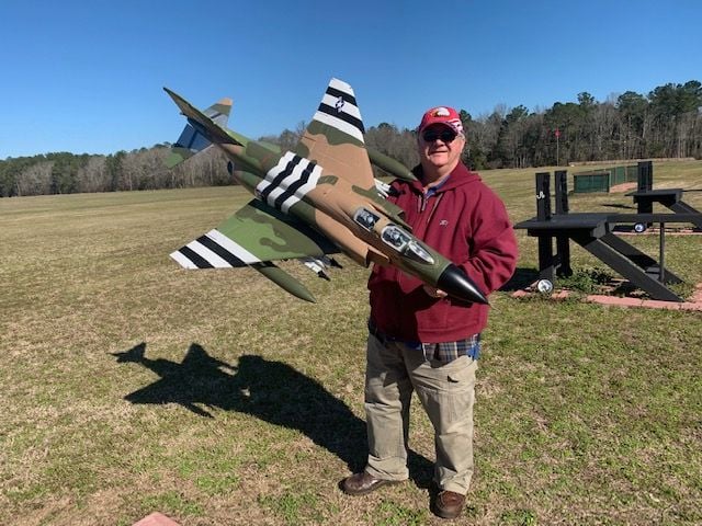
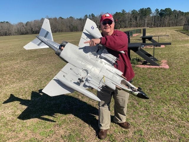
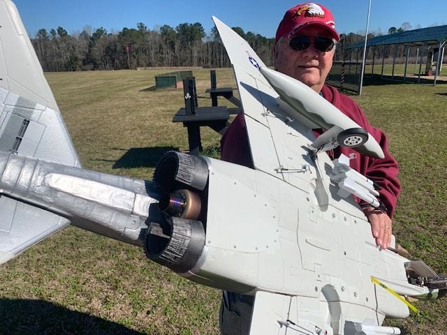
No work on F-105 today. Went out to test fly Freewing F-4 foamy turbine conversion. Took off flew for about 3 min and flamed out. Looks like air into turbine. Probably faulty home made air trap. Dead stick gear up landing cleaned off stores and broke nose cone. Will redo fuel system and try again later. Was good to get out of shop on nice day anyway.
01-29-2020, 07:10 AM
#512
Holy cow that’s a great conversion!! Would love to see more pix of install. The tiny rare earth magnets are all you need. And your gear will be heavy enough to break them free. I like the inner door idea as you could refill the notch you made for the tire and use that as your “ extra push “ just be sure to amp meter that servo.
01-30-2020, 04:17 PM
#513
My Feedback: (2)

Join Date: May 2002
Location: Honolulu,
HI
Posts: 924
Likes: 0
Received 0 Likes
on
0 Posts
Hello Gary
Awesome work, thank you for posting your progress.
I have an addition to Buck's (hi Buck) hint of using rare earth magnets.
I have used them on quite a few jets, you can get some very positive closing doors that way love using them.
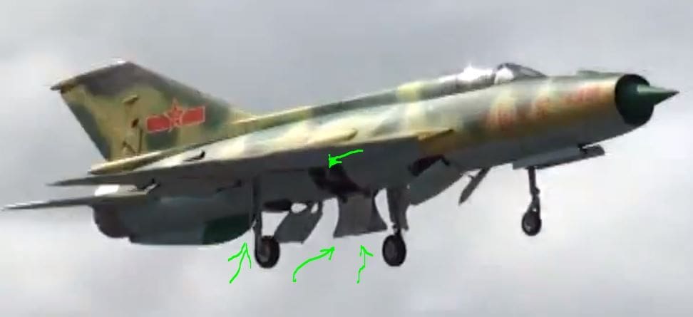
On my FeiBao Mig21 I had some issues with the doors staying closed, so i used magnets on the inner main doors and the outer strut doors. To get a positive close I used magnets on the inside and outside.
I have put green arrows where i used magnets on the picture. Over about 15 flights I have not had the doors fail to open and keep the gear locked up.
This however caused an issue with getting the gear to open at low pressures so I have resorted to using door kickers, either air cylinders or servos.
in the Mig21 i used micro servos with metal gears, I just use the servo arm like a cam so when you select down the servo turns and opens the door enough to break the magnetic connection. Takes some adjusting
but you have doors that close tight.
Still have the plane
Awesome work, thank you for posting your progress.
I have an addition to Buck's (hi Buck) hint of using rare earth magnets.
I have used them on quite a few jets, you can get some very positive closing doors that way love using them.
On my FeiBao Mig21 I had some issues with the doors staying closed, so i used magnets on the inner main doors and the outer strut doors. To get a positive close I used magnets on the inside and outside.
I have put green arrows where i used magnets on the picture. Over about 15 flights I have not had the doors fail to open and keep the gear locked up.
This however caused an issue with getting the gear to open at low pressures so I have resorted to using door kickers, either air cylinders or servos.
in the Mig21 i used micro servos with metal gears, I just use the servo arm like a cam so when you select down the servo turns and opens the door enough to break the magnetic connection. Takes some adjusting
but you have doors that close tight.
Still have the plane
01-30-2020, 05:59 PM
#514
Thread Starter
My Feedback: (20)
Thanks for the idea. This is the exact problem I was concerned about when using magnets. The idea of a door kicker seems good to me. I think an air cylinder may be the easiest and lightest method. Let me ponder that this weekend. No work done today. My wife wants a pool for grand kids this summer so prepping for that took most of the day. Hope to make some more progress this weekend.
Yeahbaby,
I will post some pics of the F-4 conversion when I get the bugs worked out. It will be in the X45/K45 thread.
Foamie jet for X45/K45 ?
My FW F-22 foamy conversion photos start at post #14 there.
Thanks again to all who offered ideas. Please keep them coming. It is really appreciate the encouragement on this project.
Gary
Last edited by Viper1GJ; 01-30-2020 at 06:07 PM.
01-31-2020, 07:22 PM
#515
Aloha Duke glad to see you still flying that Mig. Hope to see you on one of our birds in the coming year. The magnets work amigo a door kicker is a great addition but i guarantee your gear is heavy enough to kick them open under a light G load. A xicoy one way valve with a couple of ( insert your favorite ) brand cylinder would be cheap insurance. Only activated on door open side should do it.
02-01-2020, 04:55 PM
#516
Thread Starter
My Feedback: (20)
I'm thinking the magnets and air cylinder kickers are the way to go. I have to get the main doors fastened to the struts and then the outer doors hinged and linked to the struts first. Then I will add some air and see what happens. Spent all day fixing the foamy F-4 so no work on 105 today.
02-06-2020, 06:26 PM
#517
Thread Starter
My Feedback: (20)
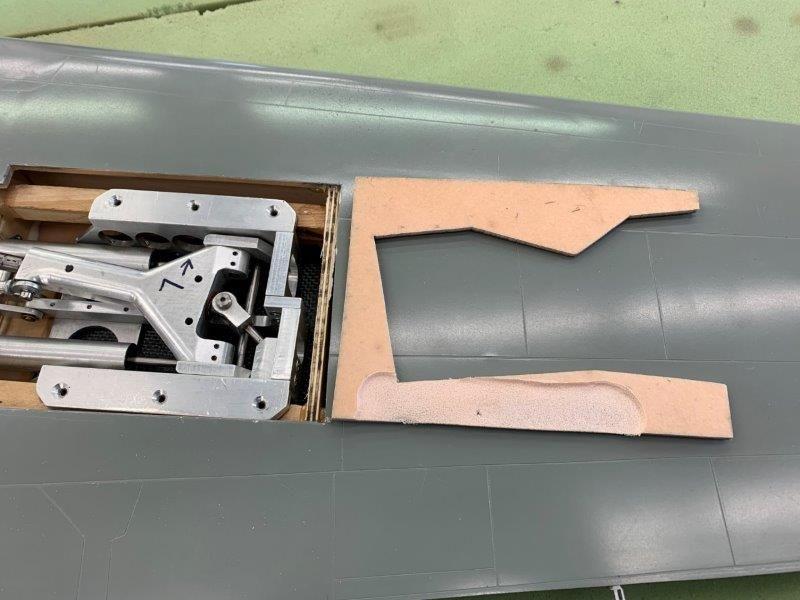
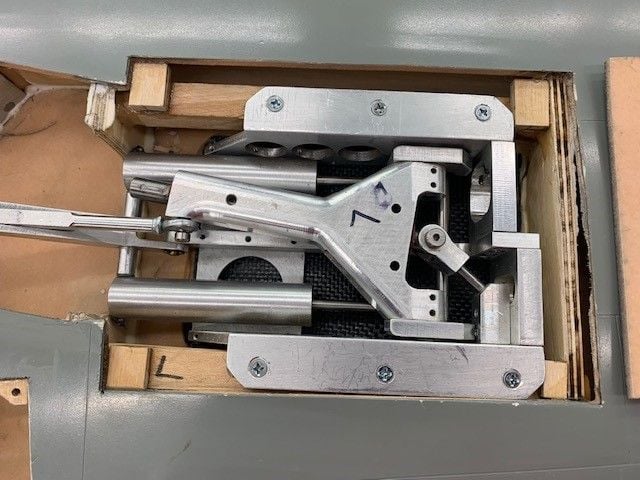
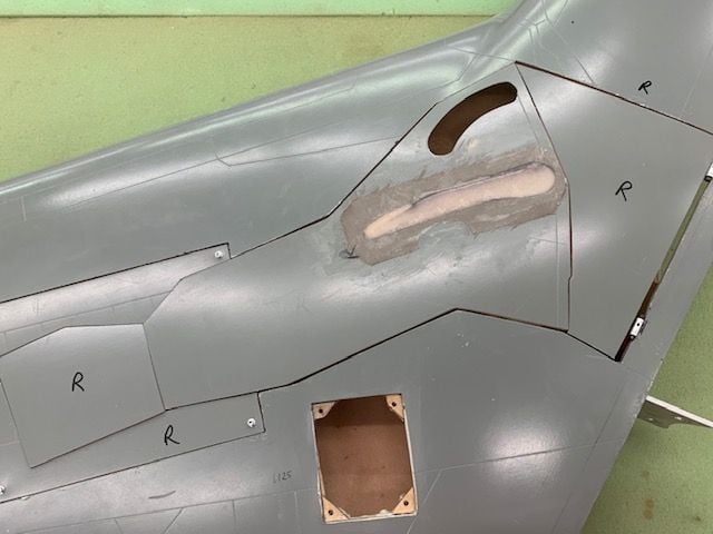
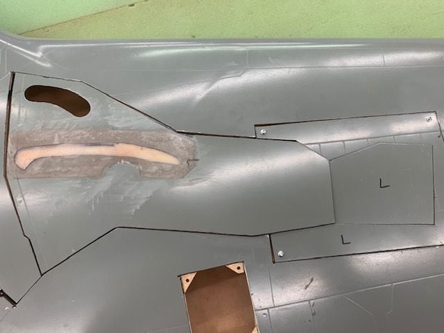
Fitting gear mount covers
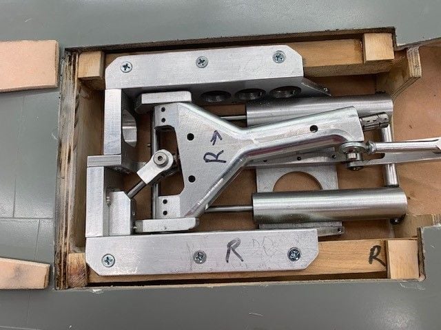
Added mounting shims to each corner of gear mount opening. As usual each corner had to be custom fit for thickness. Each was different so it took some time to get them done on disc sander. Epoxied in.
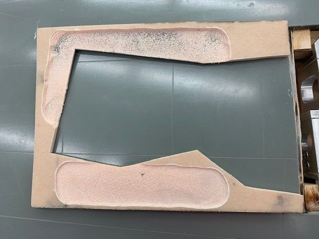
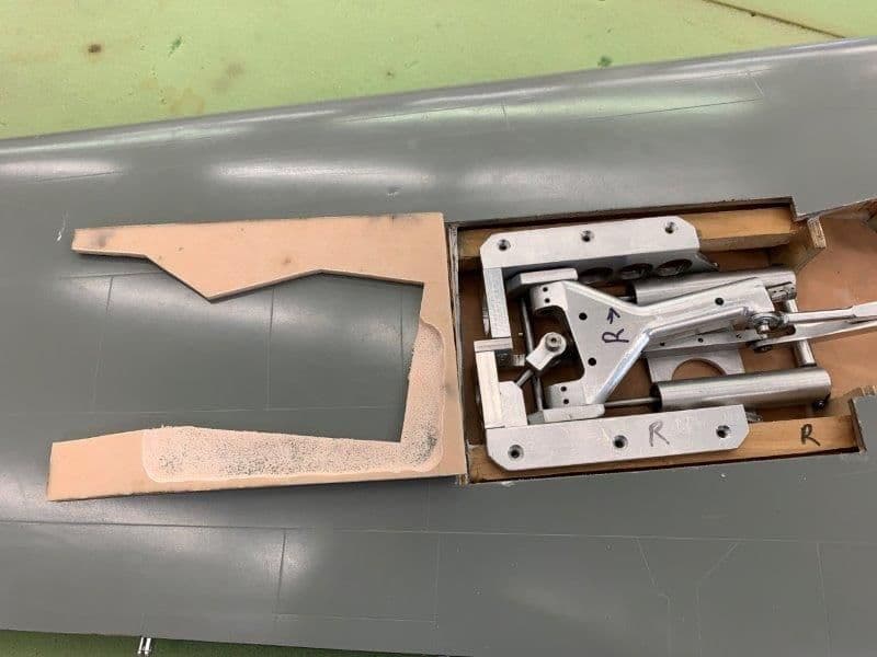
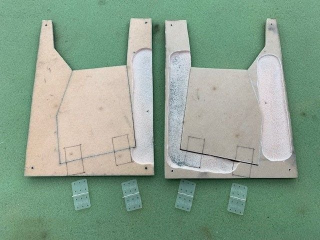
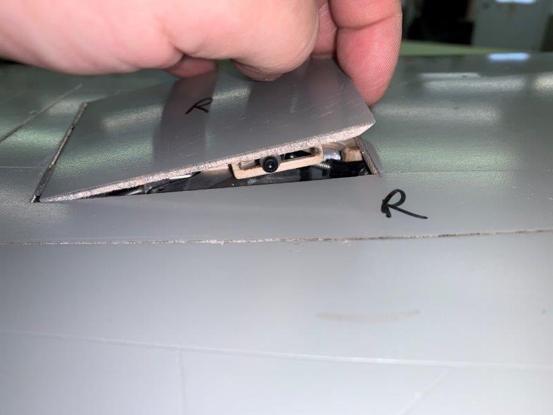
Gear mount covers had to be ground out to clear the aluminum mounts.
Both sides ready
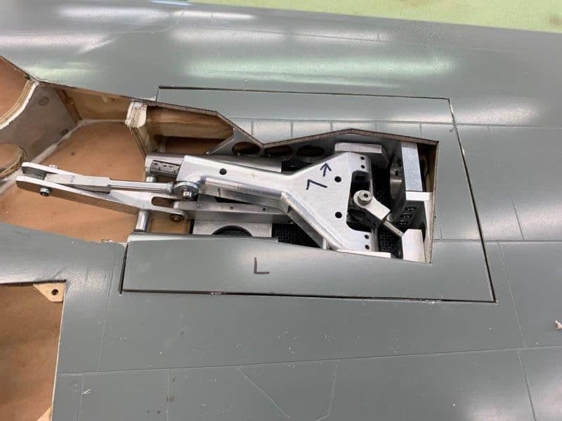
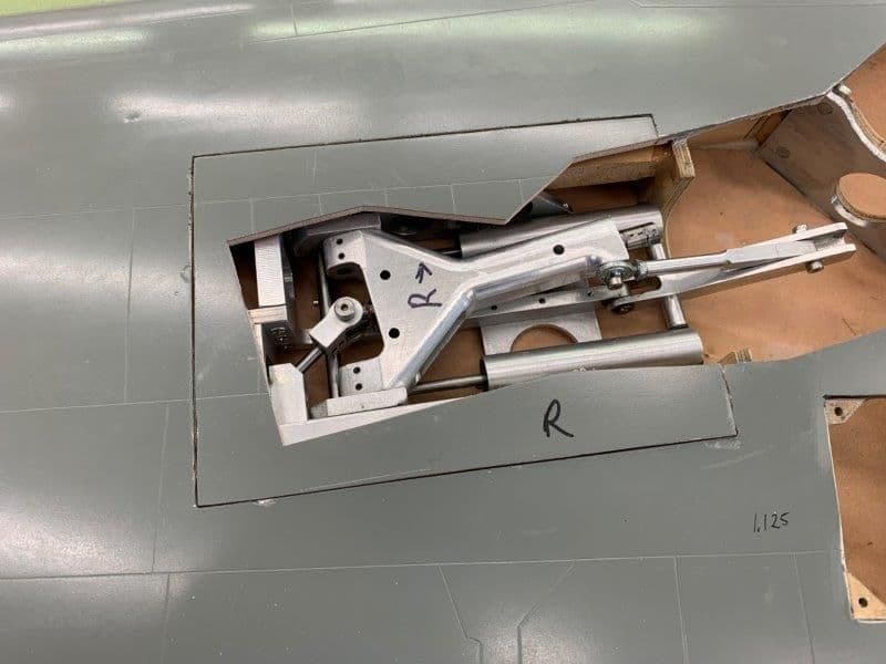
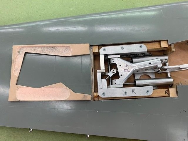
Flush with wing skin now.
Left side done the same
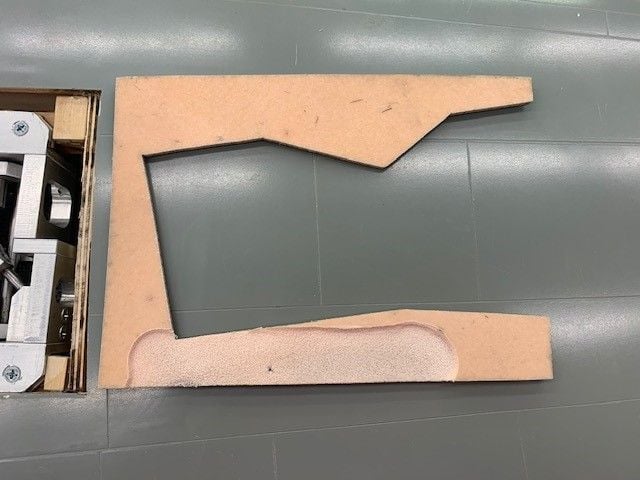
Relief cutout
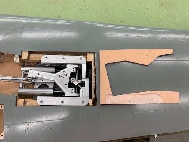
Ready to fit
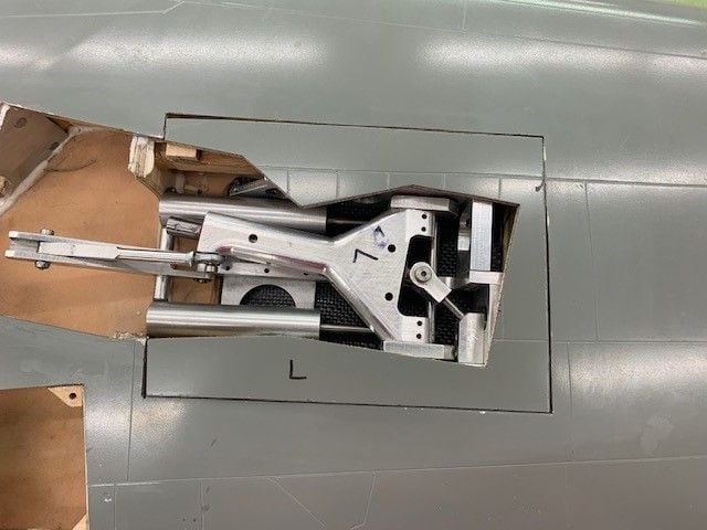
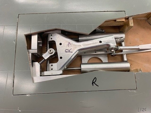
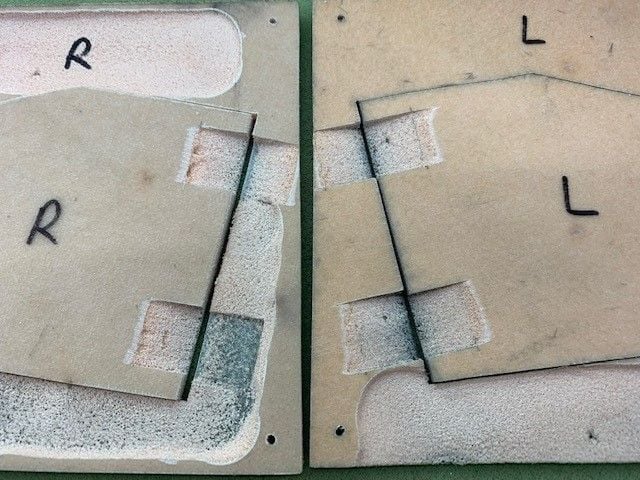
Both sides done. I'm debating whether to drill and countersink for flush screws or use servo screws. Countersink will have to be done into the soft foam below the glass surface and may not hold well. Servo screws will hold on glass surface.
Added mounting shims to each corner of gear mount opening. As usual each corner had to be custom fit for thickness. Each was different so it took some time to get them done on disc sander. Epoxied in.
Gear mount covers had to be ground out to clear the aluminum mounts.
Both sides ready
Flush with wing skin now.
Left side done the same
Relief cutout
Ready to fit
Both sides done. I'm debating whether to drill and countersink for flush screws or use servo screws. Countersink will have to be done into the soft foam below the glass surface and may not hold well. Servo screws will hold on glass surface.

The following users liked this post:
Auburn02 (02-07-2020)
02-07-2020, 06:04 AM
#519
I love threads like this. Come for the progress, stay for the tips I would have never thought of but will remember forever.
02-07-2020, 07:11 PM
#520
Thread Starter
My Feedback: (20)
Great idea, I like that solution. I have to get some more flat head screws and I will use the hysol fill for the countersink. I love this forum for all the tips and ideas. Thanks again Thomas.
For now the gear covers are screwed on with servo screws. Servo screws are a temp fix until I can countersink holes and use flat head screws.
Next step is hinging and connecting the small outer doors to the struts
For now the gear covers are screwed on with servo screws. Servo screws are a temp fix until I can countersink holes and use flat head screws.
Next step is hinging and connecting the small outer doors to the struts
02-13-2020, 07:02 PM
#521
Thread Starter
My Feedback: (20)
Outer gear door hinging
Relief cuts to clear the gear mounts in bottom of mount covers. Hinge placement marked
Foam material removed to allow hinge line to be flush with bottom surface

Outer doors taped in place for tack gluing with medium CA. Balsa spacer needed to ensure doors clear the skin when open.
Hinges tack glued in on bottom side
Doors now swing open and clear the bottom piece

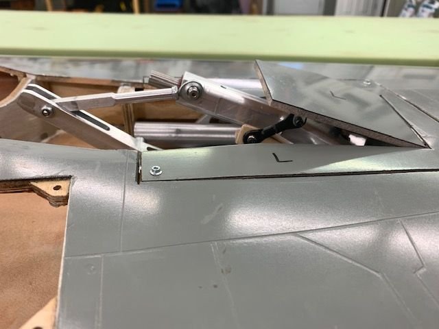
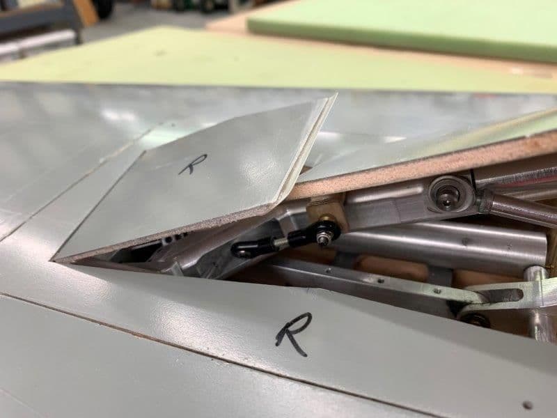
In closed position. There is about 6mm spacing between door and gear strut to install the linkage.
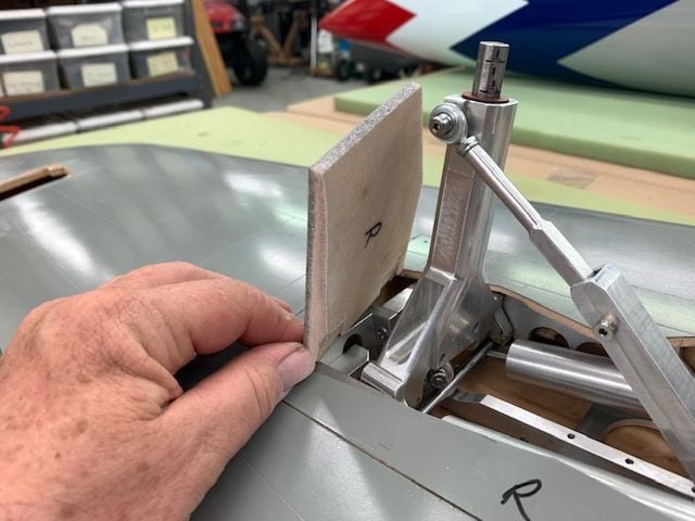
Staring at the door and strut thinking about a linkage set up
Simulating a turnbuckle style link with 2-26 or 4-40 ball links from the strut arm to the door
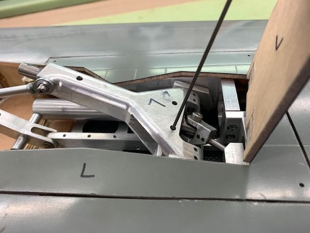
Existing holes will allow a bracket to be bolted to the strut to hold the turnbuckle link to the strut side. My friend Keith will help me make a 3D printed bracket that will fit the pre existing holes and be adjustable in height to help get the correct geometry set. I plan to make a wood mockup to test the concept first.
Relief cuts to clear the gear mounts in bottom of mount covers. Hinge placement marked
Foam material removed to allow hinge line to be flush with bottom surface
Outer doors taped in place for tack gluing with medium CA. Balsa spacer needed to ensure doors clear the skin when open.
Hinges tack glued in on bottom side
Doors now swing open and clear the bottom piece
In closed position. There is about 6mm spacing between door and gear strut to install the linkage.
Staring at the door and strut thinking about a linkage set up
Simulating a turnbuckle style link with 2-26 or 4-40 ball links from the strut arm to the door
Existing holes will allow a bracket to be bolted to the strut to hold the turnbuckle link to the strut side. My friend Keith will help me make a 3D printed bracket that will fit the pre existing holes and be adjustable in height to help get the correct geometry set. I plan to make a wood mockup to test the concept first.
Last edited by Viper1GJ; 02-13-2020 at 07:05 PM.
02-14-2020, 06:38 PM
#522
Thread Starter
My Feedback: (20)
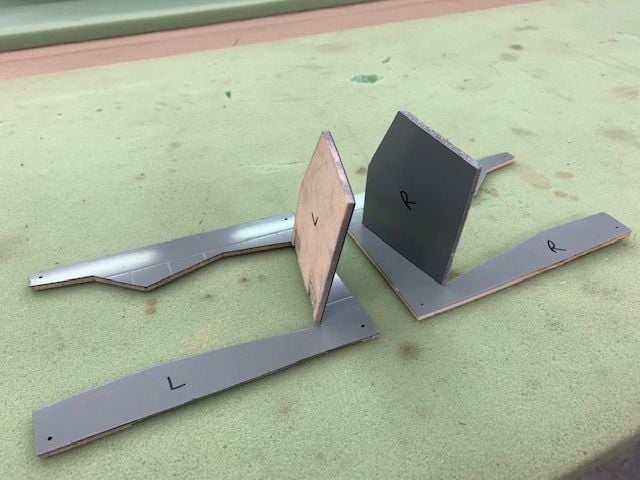
Outer gear door linkage. Spent all day working on a linkage geometry that would work. Finally got it working. The idea was to develop a working wood mock up and then get Keith to 3D print a usable bracket.
Big problem is the hinge line of the gear trunion and the door are not parallel. This causes the linkage to have to move in all 3 axies when moving from gear up to gear down.
After several hours of staring at it I made a paper template that used existing holes in the gear trunion to hold a door bracket in place.
Paper pattern made to wood mockup. Keith recommended an adjustable bracket so I added a top piece with the concept of making it slide up and down in a screw slot.
4-40 Dubro links cut down to make a small turnbuckle style link to the door
First test showed the wood mock up too thick to close the door. The adjustable bracket did not seem to be needed since the link was adjustable so I removed the adjustable layer. Now the link hit the edge of the gear mount cover. So I cut off 3mm from the trailing edge of the bracket and the link cleared the cover. However now the door hit the top of the socket head bolts and would not close completely.
Cutting off the edge of the bracket cleared the cover but now the link would hit the trunion when closed if it was aligned with the strut.
Next I made another bracket that was taller so the link would clear the trunion. Also I found some thin round head screws and the door would close.
The trick was where to place the door attach lug to keep the link from hitting the trunion. Got that fixed and found that when the gear retracts the link becomes near parallel with the door and has no leverage to close the door. I needed to lower the ball link on the strut side to get more pull on the door when retracted.
Last edited by Viper1GJ; 02-14-2020 at 07:30 PM.
02-14-2020, 06:52 PM
#523
Thread Starter
My Feedback: (20)
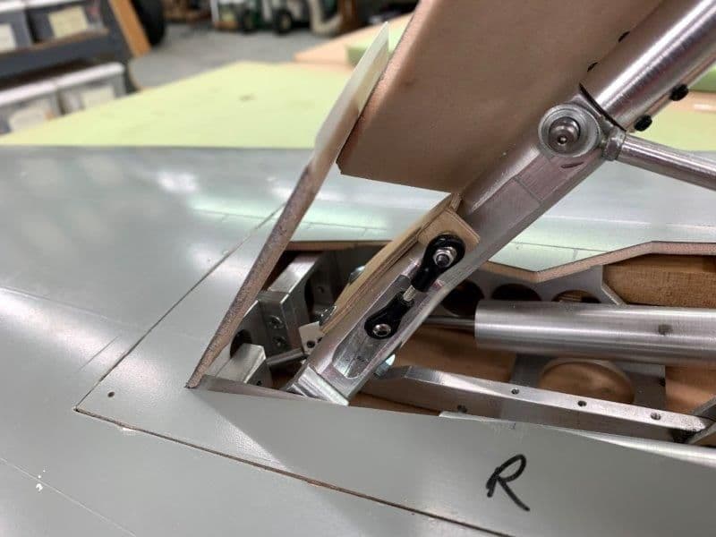
Next try was to move the bracket to the bottom of the strut. This allowed the use of the socket head bolts again and gave the link more of an angle from the door to pull when retracted. However there was binding of the link on both ends of the retract cycle due the hinge lines of the trunion and door not being parallel.
Next try was to stack bushings under the ball link to move it away from the strut to help alignment through the retract range of motion.
This geometry worked to get the door closed and just cleared the air cylinder when closed.
View from the rear when open
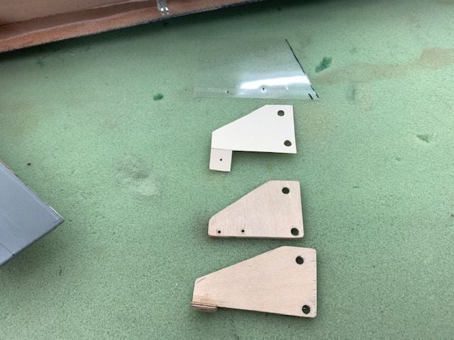
Discarded mock up brackets.
02-14-2020, 07:28 PM
#524
Thread Starter
My Feedback: (20)
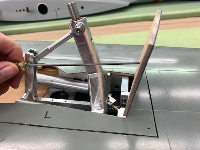
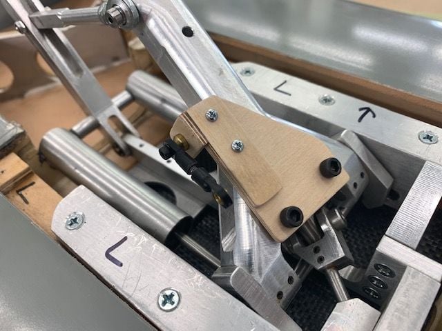
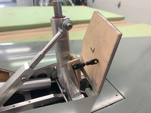
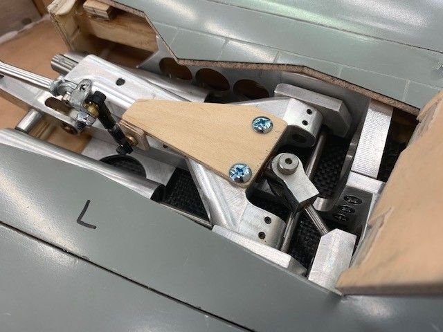
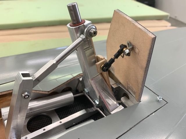
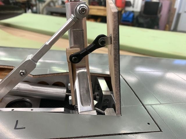
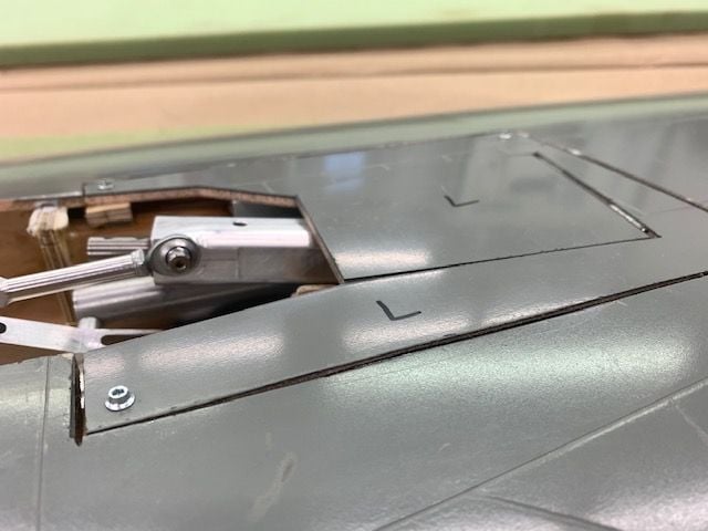
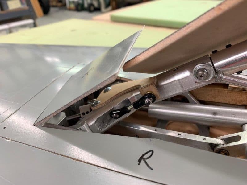
Final mock up

A new bracket was cut with a wider edge to allow removal of the bushings. This put the link more inline with the range of motion and eliminated the binding at both ends of the swing

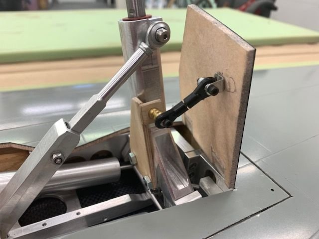
Half way down
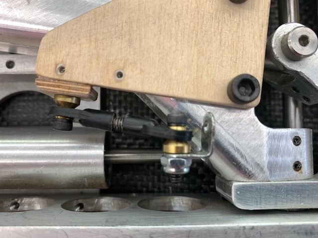
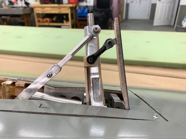
Link now more inline with strut bracket when extended
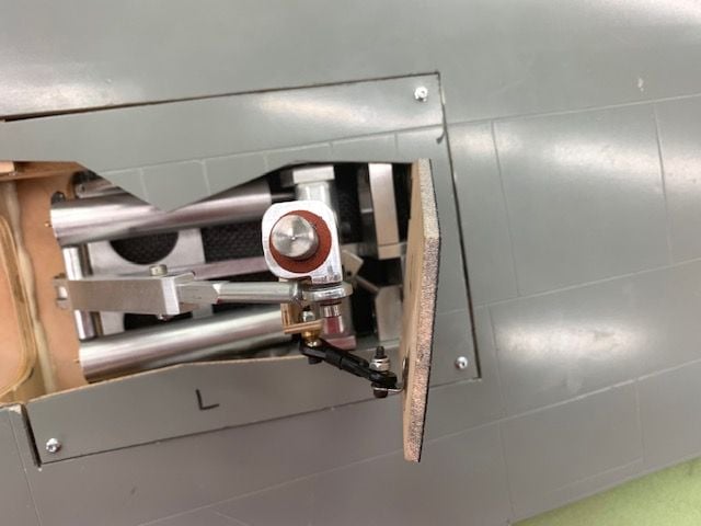
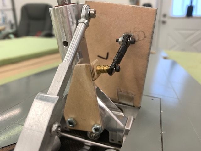
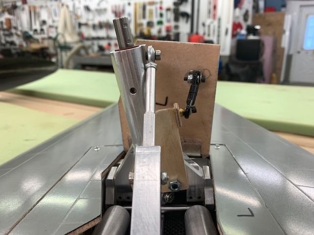
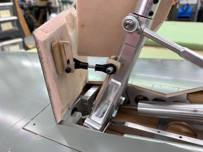
Rear view. The door lug was just tack glued to the door with medium CA for testing. It will be countersunk into the door, bolted, and filled in with hysol once the final position is determined.
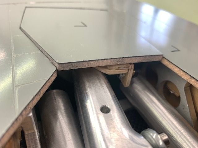
Almost closed
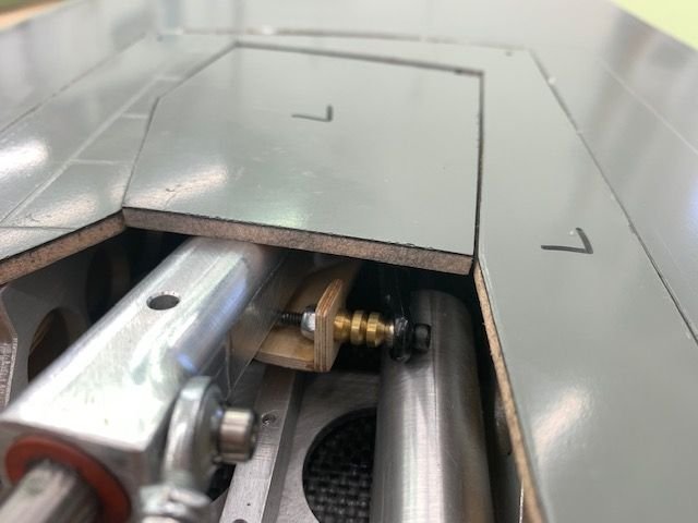
Closed. After reviewing the position of the ball link on the strut side Keith suggested a possible clamp bracket around the strut instead of the flat bracket bolted on the bottom of the strut. We will look a this next. The important thing is the location of the ball link on the strut and the lug on the door. At least now I know it is possible to make it work.
A new bracket was cut with a wider edge to allow removal of the bushings. This put the link more inline with the range of motion and eliminated the binding at both ends of the swing
Half way down
Link now more inline with strut bracket when extended
Rear view. The door lug was just tack glued to the door with medium CA for testing. It will be countersunk into the door, bolted, and filled in with hysol once the final position is determined.
Almost closed
Closed. After reviewing the position of the ball link on the strut side Keith suggested a possible clamp bracket around the strut instead of the flat bracket bolted on the bottom of the strut. We will look a this next. The important thing is the location of the ball link on the strut and the lug on the door. At least now I know it is possible to make it work.
Last edited by Viper1GJ; 02-14-2020 at 07:35 PM.
02-18-2020, 07:10 PM
#525
Thread Starter
My Feedback: (20)
Well I thought the rest of the doors would be easy. Ha! Everything in the last 2 posts went into the trash. In my one dimension linear mind and without the lower strut on the main trunion I did not see that the gear was binding on the plywood bracket I put on the bottom of the trunion. It would not go all the way in. So after another day I got it back on the top and working. Oh I was so proud of my self. And then I tried to put on the main doors. I thought the inner doors were done, the outer doors were done and the main doors were done. Just put them all on and done! Well, not so fast...
 t
t
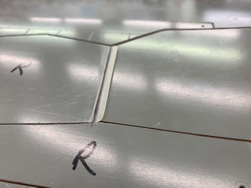
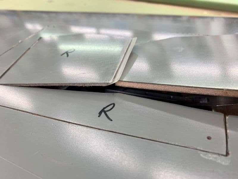
The first thing I ran into was the main door and the outer door hit each other as soon as the gear tried to extend and locked it up. After studying several photos and videos I saw that other builders had tapered the edge of the outer door and added a small shim to ensure that the main door went under the outer door on extension. So I added a shim or faring to the outer door and solved that problem. It forces the main door under the outer door.
And then the next disaster was discovered...

As seen above the main door drops below the top of the outer door about 1.5" and directly conflicted with my last two days design and linkage. As can be seen in the above posts my outer only opened about 80 degrees. It needed about 110 degrees to clear the main door because of the rotation when the gear extends.
For the next two days I could not get anything to work. I considered pushrods, nyrods, linear servos, regular servos, springs, rubberbands, elastic thread, and smashing the whole thing with a hammer.
The problem I had was everything bumped in to everything else in the gear well. Also the leverage needed to close the door was not there unless the ball link was deep enough in the gear well to pull it shut. It all had to fold flat and the hinge lines of the door and gear were not aligned causing the link to have to move sideways through the range of motion.
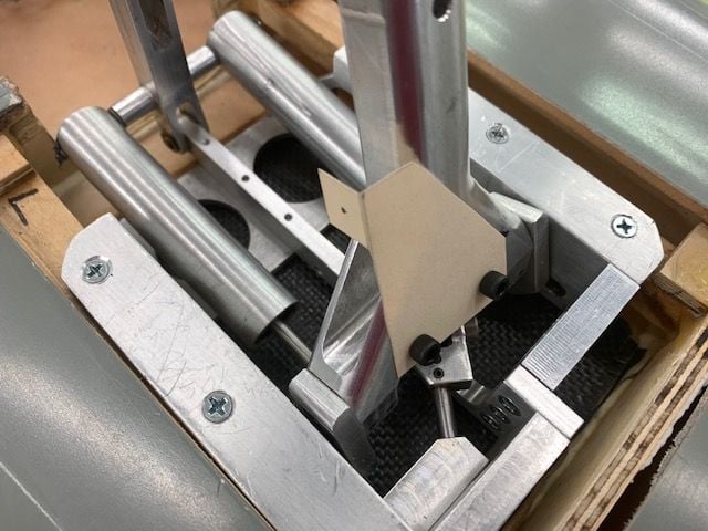
I wont even try to show all the different combos of stuff I tried but today I tried a slotted lug on the door to compensate for the different lengths required as the door moves. My crude wood mock up would bind but I think the concept may work if I can get some decent hardware. Also I ordered some 2-56 ball links to save space in the gear well since the 4-40 links were so big and caused problems with clearance from other parts.
As the door closes the link slides in the slot. This mock up would not completely close because of the slot bracket hit the trunion but I think it can be done. I'm just frustrated with it and done with it for now. As stated early in the project the main gear was going to be a problem. So far it has been the hardest part and I am in over my head with fixing it. I can't machine any thing and that is what is needed to solve the problem of the gear doors being flush with the lower wing skin. As of now I have about 1/4" hanging out on the leading edge of the gear doors because the rotation angle is not correct to track straight when extended and fold into the wing when retracted. All this is too much for me now and I'm moving on to some other part I can work on.
tThe first thing I ran into was the main door and the outer door hit each other as soon as the gear tried to extend and locked it up. After studying several photos and videos I saw that other builders had tapered the edge of the outer door and added a small shim to ensure that the main door went under the outer door on extension. So I added a shim or faring to the outer door and solved that problem. It forces the main door under the outer door.
And then the next disaster was discovered...
As seen above the main door drops below the top of the outer door about 1.5" and directly conflicted with my last two days design and linkage. As can be seen in the above posts my outer only opened about 80 degrees. It needed about 110 degrees to clear the main door because of the rotation when the gear extends.
For the next two days I could not get anything to work. I considered pushrods, nyrods, linear servos, regular servos, springs, rubberbands, elastic thread, and smashing the whole thing with a hammer.
The problem I had was everything bumped in to everything else in the gear well. Also the leverage needed to close the door was not there unless the ball link was deep enough in the gear well to pull it shut. It all had to fold flat and the hinge lines of the door and gear were not aligned causing the link to have to move sideways through the range of motion.
I wont even try to show all the different combos of stuff I tried but today I tried a slotted lug on the door to compensate for the different lengths required as the door moves. My crude wood mock up would bind but I think the concept may work if I can get some decent hardware. Also I ordered some 2-56 ball links to save space in the gear well since the 4-40 links were so big and caused problems with clearance from other parts.
As the door closes the link slides in the slot. This mock up would not completely close because of the slot bracket hit the trunion but I think it can be done. I'm just frustrated with it and done with it for now. As stated early in the project the main gear was going to be a problem. So far it has been the hardest part and I am in over my head with fixing it. I can't machine any thing and that is what is needed to solve the problem of the gear doors being flush with the lower wing skin. As of now I have about 1/4" hanging out on the leading edge of the gear doors because the rotation angle is not correct to track straight when extended and fold into the wing when retracted. All this is too much for me now and I'm moving on to some other part I can work on.
Last edited by Viper1GJ; 02-18-2020 at 07:12 PM.