


1/6 F-105 Build Thread


 09-15-2019, 03:21 PM
#452

Thread Starter
My Feedback: (20)
I got the gear and 3D printed parts back from Dave and they looked great.
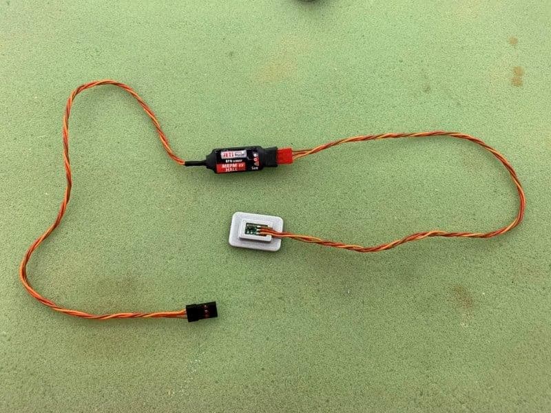
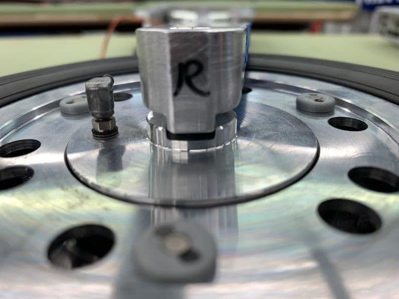
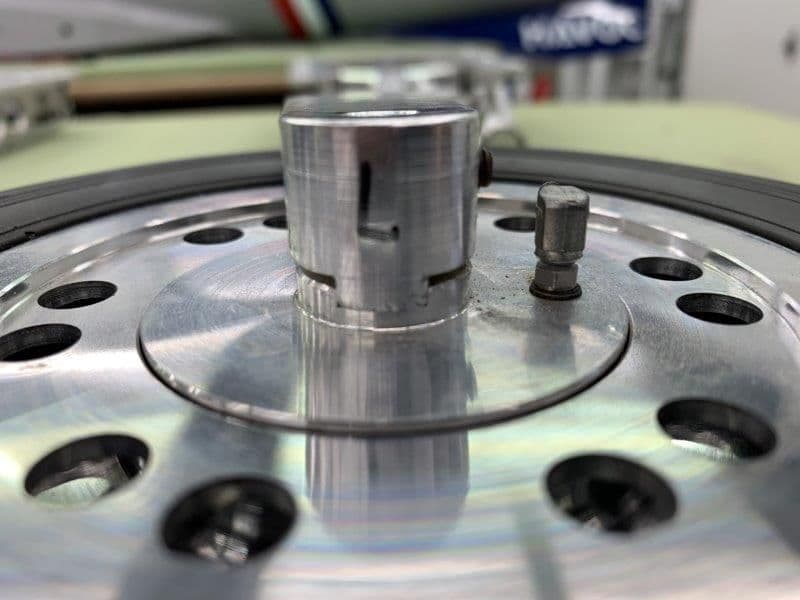
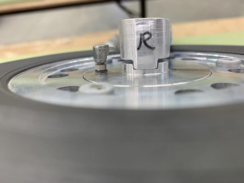
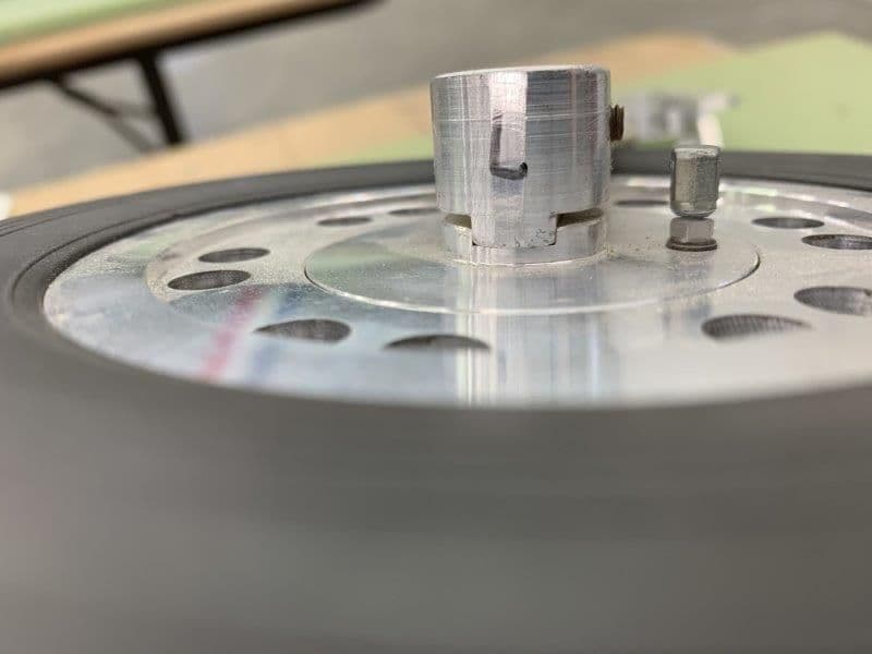
Here is the Mrpm sensor mounted into the 3D printed mounting plate
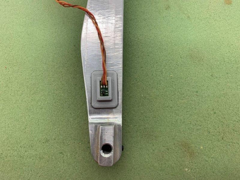
I took the wheel off the strut to positioned the sensor mounting plate.
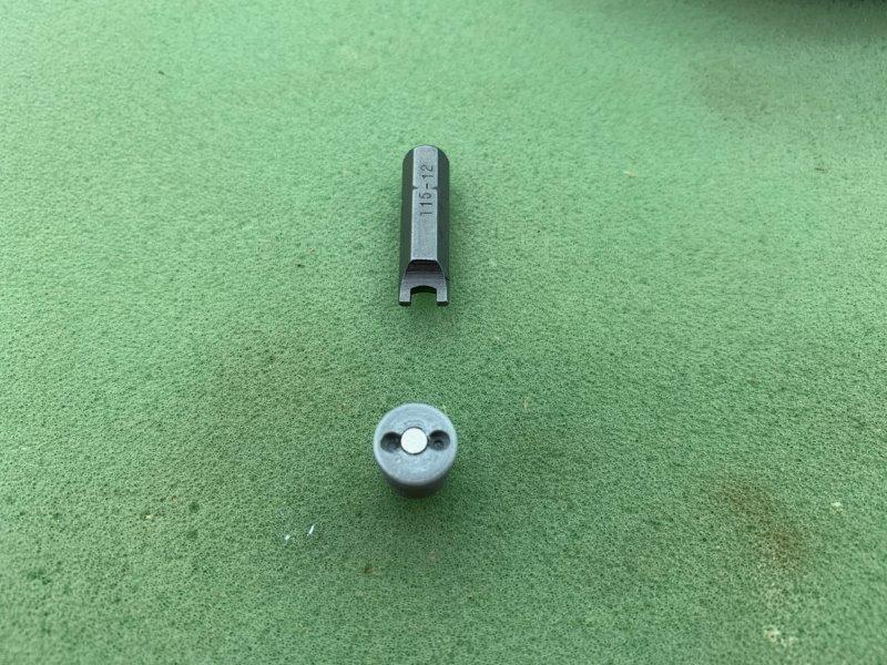
Dave made the magnets mounts to screw onto the wheel bolts with a spanner driver
Bottom holes are threaded to screw onto the bolts that hold the wheels together
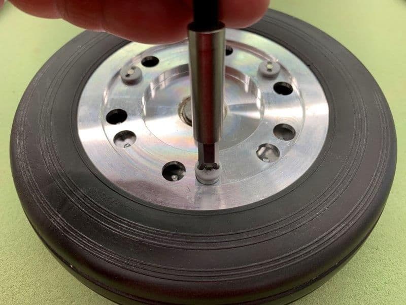
Very clever design by Dave

Sensor taped in place for testing.
Here is the Mrpm sensor mounted into the 3D printed mounting plate
I took the wheel off the strut to positioned the sensor mounting plate.
Dave made the magnets mounts to screw onto the wheel bolts with a spanner driver
Bottom holes are threaded to screw onto the bolts that hold the wheels together
Very clever design by Dave
Sensor taped in place for testing.
09-15-2019, 03:55 PM
#453
Thread Starter
My Feedback: (20)
Here is where the next problem started. While trying to put the wheel back on the right strut I found out it would not fit back on the strut. There is a tongue and groove set up between the strut and brake assembly to keep the brake disc from rotating. The strut tongue would not go into the groove on the brake assembly.
Right side had a big gap at the base of the groove. The tongue would not even enter the groove and was just sitting on top of the brake assembly
Left side seated properly in the groove. I had never seen it before but It came to me that way.
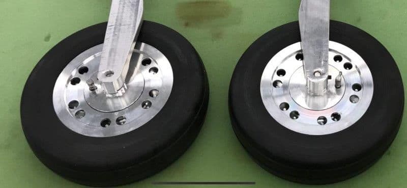
Here is an expanded photo of the gear after I unpacked them last summer. This photo was taken on 8/28/2018 and was taken on the layout posted in post #4 of the build thread. The right gear is on the left in the photo and you can see the gap there.
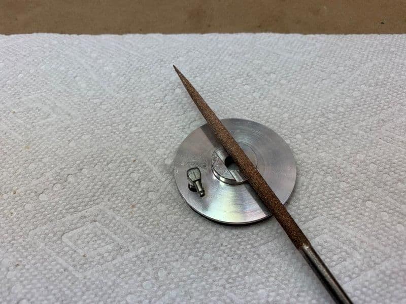
So I started slowly working the brake assembly with a perma grit square file.
 \
\
After about 30 min I got it to fit. Now it is seated properly like the left gear below.
Left gear seated properly. And I was so happy that I had fixed another problem on the F-105 build. Well, not so fast...

Fixing the gear problem reduced the clearance to nil between the Mrpm sensor and the magnets. So the saga continues...
Right side had a big gap at the base of the groove. The tongue would not even enter the groove and was just sitting on top of the brake assembly
Left side seated properly in the groove. I had never seen it before but It came to me that way.
Here is an expanded photo of the gear after I unpacked them last summer. This photo was taken on 8/28/2018 and was taken on the layout posted in post #4 of the build thread. The right gear is on the left in the photo and you can see the gap there.
So I started slowly working the brake assembly with a perma grit square file.
\After about 30 min I got it to fit. Now it is seated properly like the left gear below.
Left gear seated properly. And I was so happy that I had fixed another problem on the F-105 build. Well, not so fast...
Fixing the gear problem reduced the clearance to nil between the Mrpm sensor and the magnets. So the saga continues...
Last edited by Viper1GJ; 09-15-2019 at 04:00 PM.
09-15-2019, 04:18 PM
#454
Thread Starter
My Feedback: (20)
Well I whined to Dave and he had the solution immediately. Not only is he really smart, he's quick!
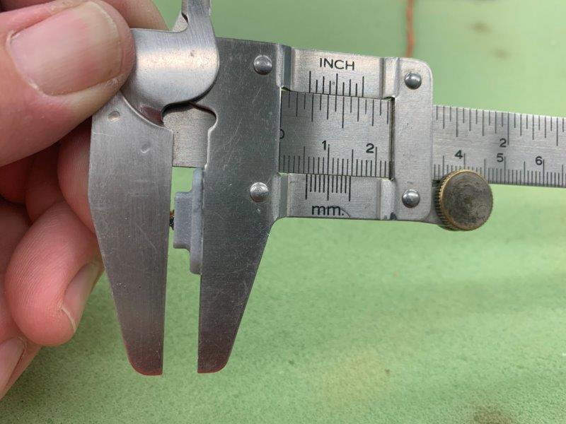
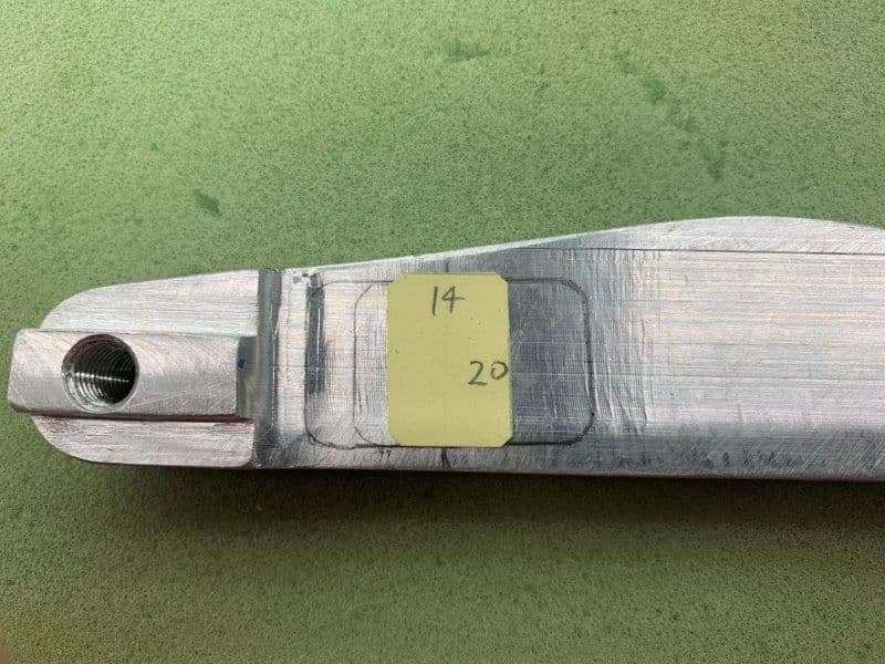
Here is the first sensor plate. It was designed for all the "extra" clearance on the right gear that I took out when I fixed the problem. It was 5.5mm thick.
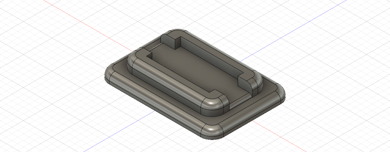
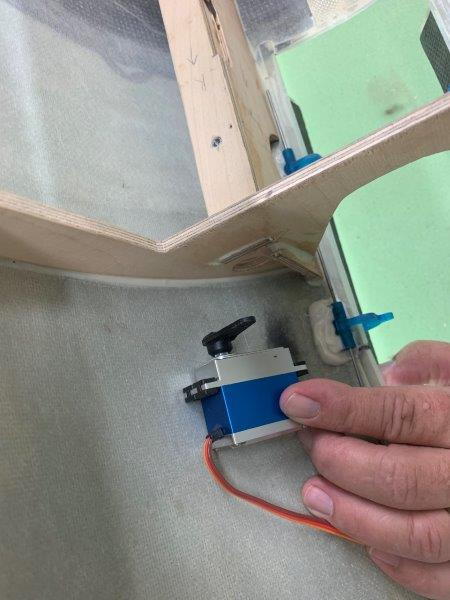
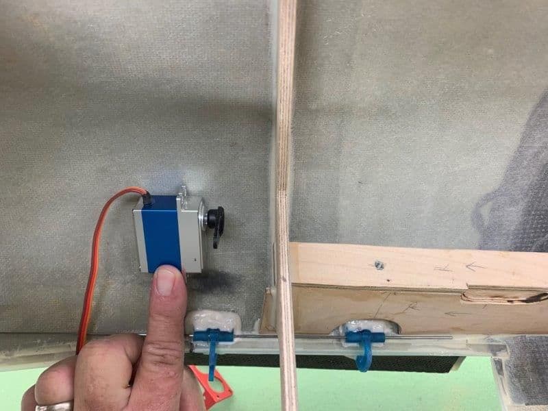
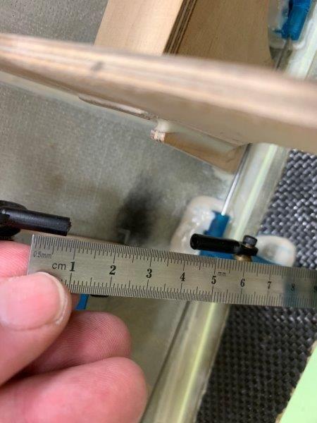
Here is Dave's Version 2 mounting plate. It's 14 x 20 mm, smaller than the first and designed to fit sideways on the strut to have the wire come out to the rear not the top. It is only 4.3mm thick including the sensor. It has an extra slot to assist in removal of the sensor if needed. The sensor is attached with Goop or similar soft glue.
Here is my mock up of the new plate mounting. You can see the traces of the old position.
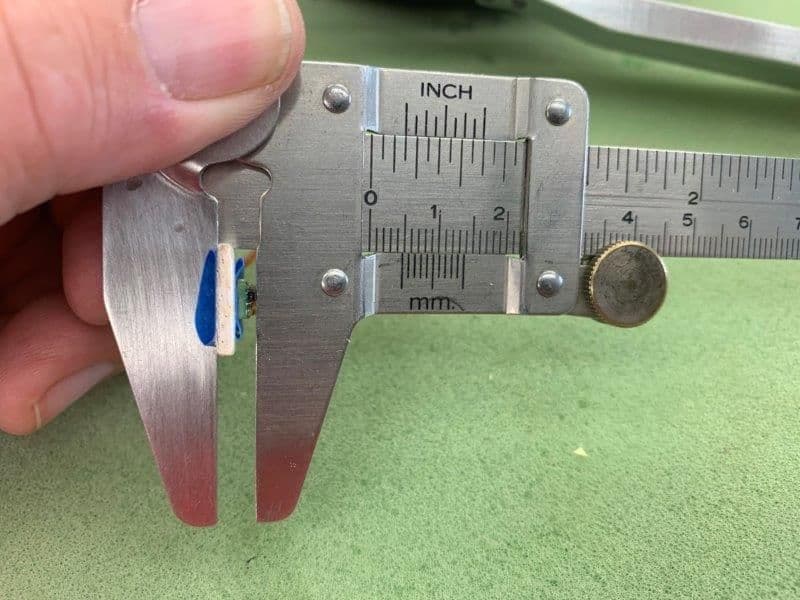
I mocked up a blue tape test mounting for testing. It is 4.5mm thick.
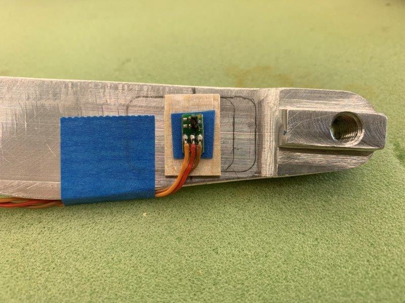
Mock up in position. The line under the balsa base is the magnet location on the wheel.
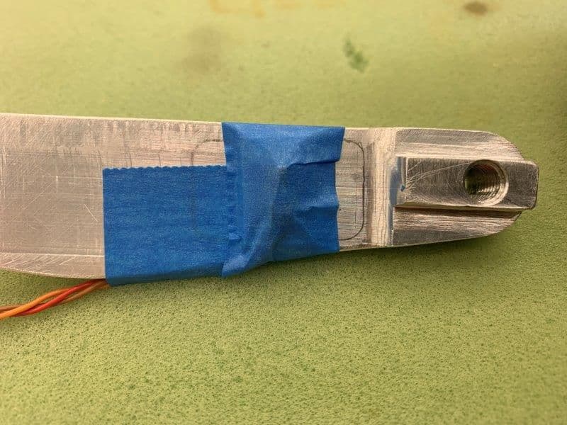
Taped on ready for testing
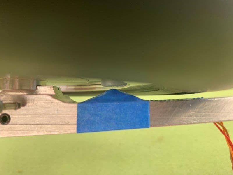
At least 1mm clearance now.
Here is the first sensor plate. It was designed for all the "extra" clearance on the right gear that I took out when I fixed the problem. It was 5.5mm thick.
Here is Dave's Version 2 mounting plate. It's 14 x 20 mm, smaller than the first and designed to fit sideways on the strut to have the wire come out to the rear not the top. It is only 4.3mm thick including the sensor. It has an extra slot to assist in removal of the sensor if needed. The sensor is attached with Goop or similar soft glue.
Here is my mock up of the new plate mounting. You can see the traces of the old position.
I mocked up a blue tape test mounting for testing. It is 4.5mm thick.
Mock up in position. The line under the balsa base is the magnet location on the wheel.
Taped on ready for testing
At least 1mm clearance now.
09-15-2019, 05:10 PM
#455
Thread Starter
My Feedback: (20)
Dave sent me his latest version of the drag chute Lua program and I installed the files in my DS-24. I activated the Lua program and set up the functions for chute door, chute deploy, and chute jettison that the program creates. Then I assigned channels in servo setup and plugged in 3 servos for door, deploy, and jettison.
Here are the screens that the chute current Lua program sets up.
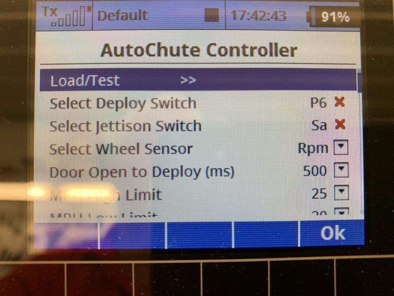
The main screen allows selection of switches, RPM sensor, time delay for deployment after door open.

There is a selectable high speed and low speed and option to have chute at mid flap setting, ie half flaps. The idea for the speed is that after touch down the wheels have to see at least the high speed first and then see the lower speed to allow the chute to deploy. I set these at first to 25 and 20 mph for bench testing.
There is another program screen where you specify all the switches for the consent conditions but I did not take photos of it. That is the screen where you tell it what the diameter of the wheel is to determine speed from RPM.
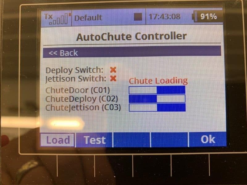
If you select the load test option at the top of the first page you get the load test page. This photo shows Load selected which opens the door and jettison hook so you can load the chute.
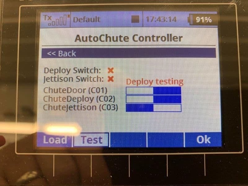
This photo shows the test function that allows ground or bench testing by opening the door and deployment spring or air cylinder with out having to have all the normal conditions met

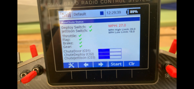
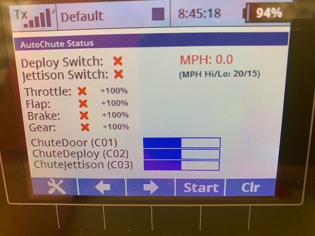
This is the status page that shows current status of all the chute deployment consent conditions. This is how it would look during normal flight after gear and flaps are retracted.
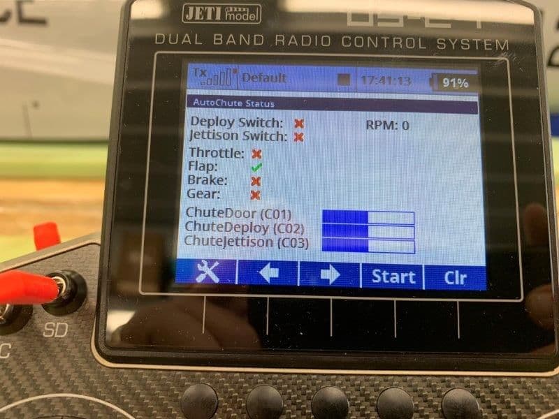
Beginning a landing approach flaps are extended
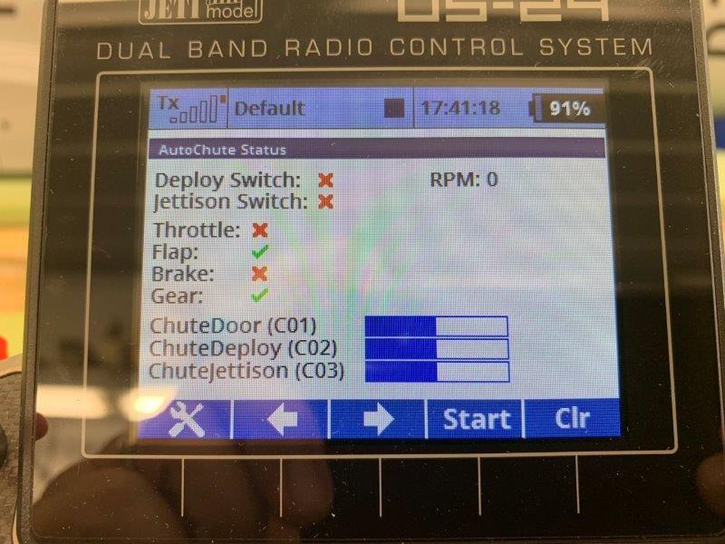
Gear is extended
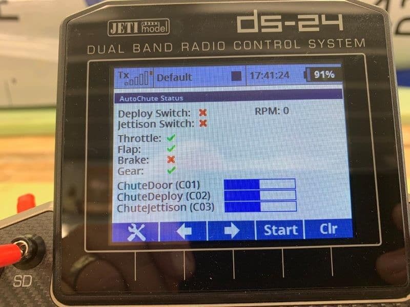
Throttle is reduced to idle
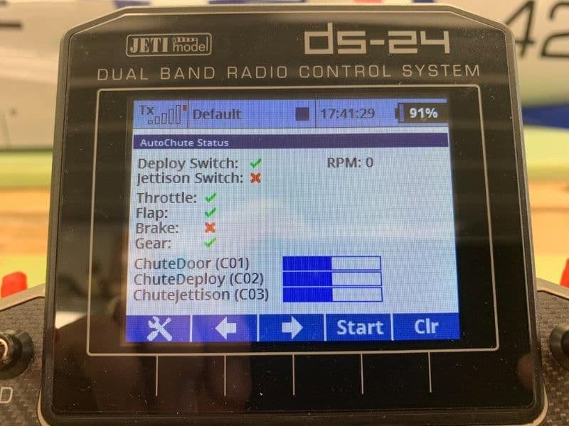
Deploy switch is activated
Brakes can be applied before or after touchdown. The wheel speed sensor would have to see the high limit followed by the low limit and then all the deploy consent conditions are met. At this time the top two blue bars move right showing servo activation of the door and deploy system...and out pops the chute!
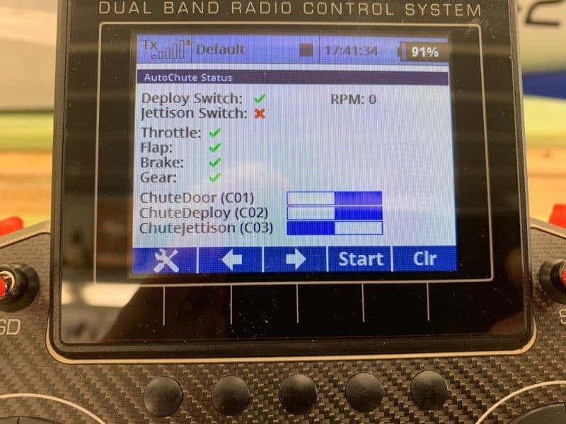
After landing the jettison switch is activated and releases the chute. Note the blue jettison bar did not move. This is because the jettison switch is a consent switch and the actual jettison occurs when flaps are raised with the jettison consent switch on. I completely forgot about how it is programmed to work when I took this photo.
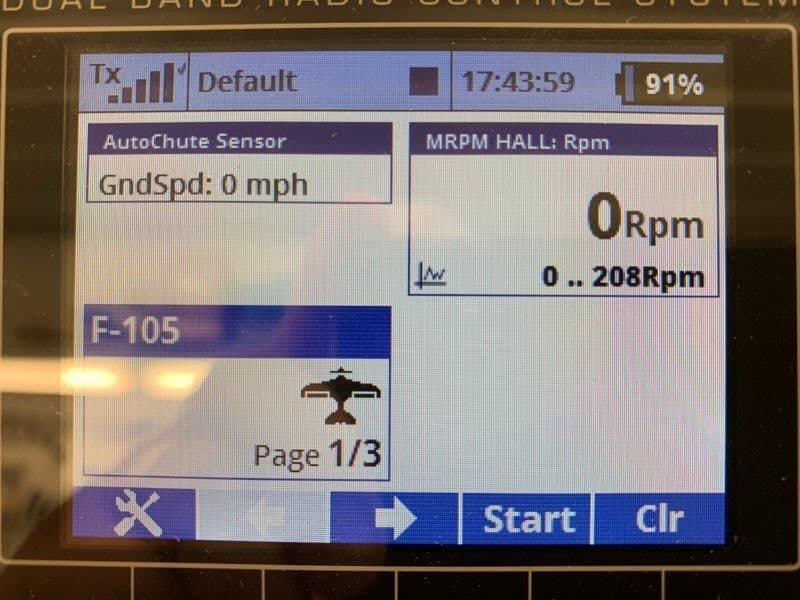
Here is the Jeti RPM telemetry window and the Autochute Sensor which calculated ground speed.
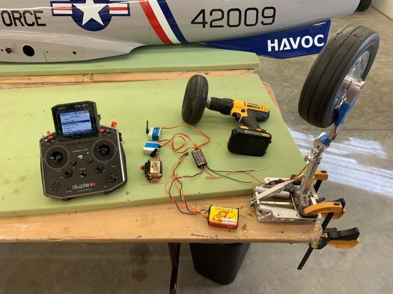
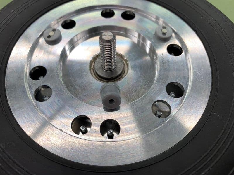
Here is my first bench test. 3 servos, Jeti receiver, battery and sensor on gear. Gear is clamped to table and cordless drill with a Carbon Z Cub wheel attached with a bolt.
Here is the concept of test. Turn the wheel with the drill, activate the switches and watch the servos activate the chute. I could only get up to 28 mph with the battery drill
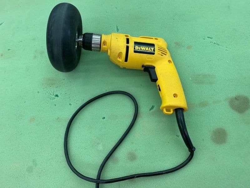
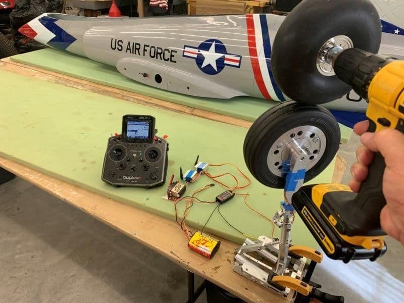
Got the "Binford 5000" more is better drill and got better speeds
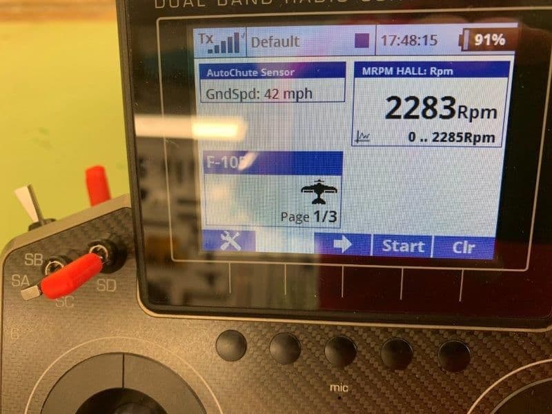
2200+ RPM and 40+ mph. I found out the wheel is way out of balance. I nor Dave have ever checked wheel balance before but is pretty bad. Any suggestions on how to balance a jet wheel would be welcome.
I found the Lua program is currently not using the speeds for deploy because I get deployment when all other conditions are met no matter that the speed is doing. Dave is working on debugging that. I'm sure it will get fixed and this will be the coolest drag chute system available.
Again, I am completely unable to do this Lua stuff without being lead by the hand and many thanks to Dave for doing just that. He thought up all these cool ideas, programmed the Lua program, designed the mounting system for the sensor and magnets, and taught me how to say "Lua". WIthout his assistance I would have glued the door shut and never considered trying it.
Many thanks Dave!
Here are the screens that the chute current Lua program sets up.
The main screen allows selection of switches, RPM sensor, time delay for deployment after door open.
There is a selectable high speed and low speed and option to have chute at mid flap setting, ie half flaps. The idea for the speed is that after touch down the wheels have to see at least the high speed first and then see the lower speed to allow the chute to deploy. I set these at first to 25 and 20 mph for bench testing.
There is another program screen where you specify all the switches for the consent conditions but I did not take photos of it. That is the screen where you tell it what the diameter of the wheel is to determine speed from RPM.
If you select the load test option at the top of the first page you get the load test page. This photo shows Load selected which opens the door and jettison hook so you can load the chute.
This photo shows the test function that allows ground or bench testing by opening the door and deployment spring or air cylinder with out having to have all the normal conditions met
This is the status page that shows current status of all the chute deployment consent conditions. This is how it would look during normal flight after gear and flaps are retracted.
Beginning a landing approach flaps are extended
Gear is extended
Throttle is reduced to idle
Deploy switch is activated
Brakes can be applied before or after touchdown. The wheel speed sensor would have to see the high limit followed by the low limit and then all the deploy consent conditions are met. At this time the top two blue bars move right showing servo activation of the door and deploy system...and out pops the chute!
After landing the jettison switch is activated and releases the chute. Note the blue jettison bar did not move. This is because the jettison switch is a consent switch and the actual jettison occurs when flaps are raised with the jettison consent switch on. I completely forgot about how it is programmed to work when I took this photo.
Here is the Jeti RPM telemetry window and the Autochute Sensor which calculated ground speed.
Here is my first bench test. 3 servos, Jeti receiver, battery and sensor on gear. Gear is clamped to table and cordless drill with a Carbon Z Cub wheel attached with a bolt.
Here is the concept of test. Turn the wheel with the drill, activate the switches and watch the servos activate the chute. I could only get up to 28 mph with the battery drill
Got the "Binford 5000" more is better drill and got better speeds
2200+ RPM and 40+ mph. I found out the wheel is way out of balance. I nor Dave have ever checked wheel balance before but is pretty bad. Any suggestions on how to balance a jet wheel would be welcome.
I found the Lua program is currently not using the speeds for deploy because I get deployment when all other conditions are met no matter that the speed is doing. Dave is working on debugging that. I'm sure it will get fixed and this will be the coolest drag chute system available.
Again, I am completely unable to do this Lua stuff without being lead by the hand and many thanks to Dave for doing just that. He thought up all these cool ideas, programmed the Lua program, designed the mounting system for the sensor and magnets, and taught me how to say "Lua". WIthout his assistance I would have glued the door shut and never considered trying it.
Many thanks Dave!
Last edited by Viper1GJ; 09-15-2019 at 05:44 PM.
 09-16-2019, 04:54 PM
#458
Thread Starter
My Feedback: (20)
Hi Thomas,
Yes it is a simple copy and paste. Dave sends me the apps as an email attachment. I download to my hard drive and then copy and paste into the Jeti DS-24 App folder. There are two Lua programs. One is the Lua app that controls the chute deployment. The other is a Lua app that contains the switches and some +/- rate info. Dave will have to explain it to you. I will post some screen shots of it below.
Once in the radio you run the programs under User Applications to see the chute menu pages. You also have to set up the functions and switches as normal in Jeti model menu. I am going to write a step by step guide for dummies so I can remember how to set it all up again in 6 months.
Gary
09-16-2019, 05:06 PM
#459
Hi Thomas,
Yes it is a simple copy and paste. Dave sends me the apps as an email attachment. I download to my hard drive and then copy and paste into the Jeti DS-24 App folder. There are two Lua programs. One is the Lua app that controls the chute deployment. The other is a Lua app that contains the switches and some +/- rate info. Dave will have to explain it to you. I will post some screen shots of it below.
Once in the radio you run the programs under User Applications to see the chute menu pages. You also have to set up the functions and switches as normal in Jeti model menu. I am going to write a step by step guide for dummies so I can remember how to set it all up again in 6 months.
Gary
Yes it is a simple copy and paste. Dave sends me the apps as an email attachment. I download to my hard drive and then copy and paste into the Jeti DS-24 App folder. There are two Lua programs. One is the Lua app that controls the chute deployment. The other is a Lua app that contains the switches and some +/- rate info. Dave will have to explain it to you. I will post some screen shots of it below.
Once in the radio you run the programs under User Applications to see the chute menu pages. You also have to set up the functions and switches as normal in Jeti model menu. I am going to write a step by step guide for dummies so I can remember how to set it all up again in 6 months.
Gary
that is pretty cool! I guess i need to just make the plunge and make the switch to Jeti on all my stuff
09-16-2019, 05:08 PM
#460
Thread Starter
My Feedback: (20)
Here are the screen shots of the other Lua app that goes with the Auto Chute app. Both Lua apps are loaded into the Jeti DS-24 and run under User Applications.
I just fill in the blanks. Dave will have to explain the apps in more detail.
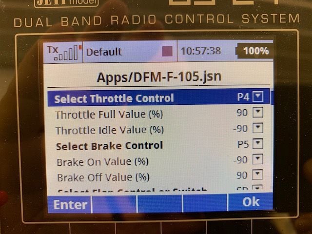
This is the top of the jsn app page. The program automatically names itself after the model name. You assign the switches or controls for each function and the rate values. They default as shown and it works fine.
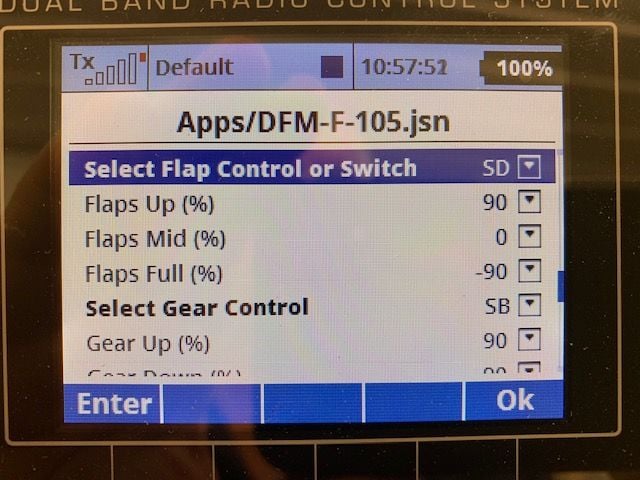
Second page...
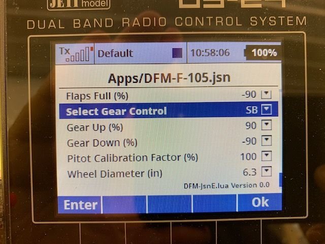
Last page. Here is the place to put in the wheel diameter so the program can convert RPM to MPH. The pitot calibration is for use with the Jeti Mspeed system. I will be using it on the F-105. I am currently using it on my 1/5 F-16 and F-22 foamy EDF and it works well but needs to be calibrated. Dave can explain more.
I just fill in the blanks. Dave will have to explain the apps in more detail.
This is the top of the jsn app page. The program automatically names itself after the model name. You assign the switches or controls for each function and the rate values. They default as shown and it works fine.
Second page...
Last page. Here is the place to put in the wheel diameter so the program can convert RPM to MPH. The pitot calibration is for use with the Jeti Mspeed system. I will be using it on the F-105. I am currently using it on my 1/5 F-16 and F-22 foamy EDF and it works well but needs to be calibrated. Dave can explain more.
09-16-2019, 05:43 PM
#461
Thread Starter
My Feedback: (20)
Here are some screen shots I grabbed off of a short video I made today of the chute status page during bench testing.
Dave sent me an update and everything is working as designed. Its really a slick system and could have applications for more than just a drag chute. As my friend Frank said today....spoilers, speedbrakes, auto brakes, etc....
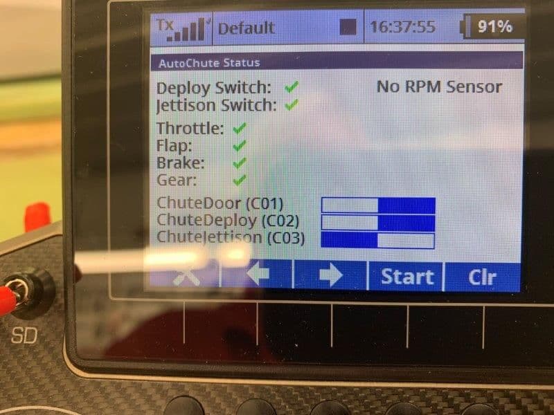
This screen shot shows just after a simulated landing with all deployment consent conditions armed and green but the ground speed is still above the high limit (shown in red) and the blue bars are in the closed pre-deployment positions. Note if desired, the jettison switch can be armed before landing but jettison will not occur until flaps are raised. No need to mess with another switch on landing roll or taxi back, just raise the flaps and the chute drops off.
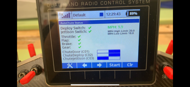
This screen shot shows ground speed below the low limit in green and the blue bars on the right shows the chute door and deployment was commanded at the low limit of 18 mph. The door would be open and the chute would be out now.
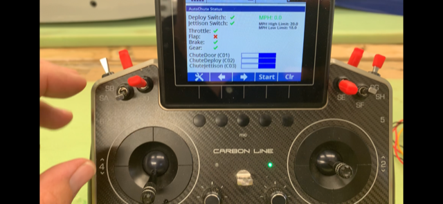
This screen shot shows a simulated taxi back and my fingers just after raising the flaps with the jettison consent armed and green and the jettison blue bar is on the right. The chute would have been jettisioned when flaps were raised.
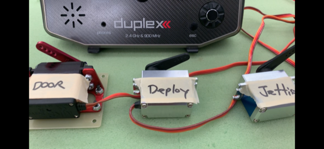
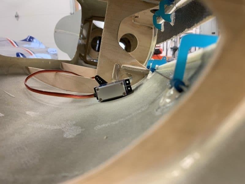
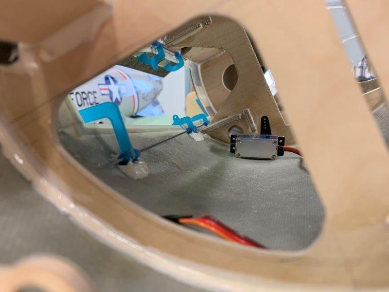
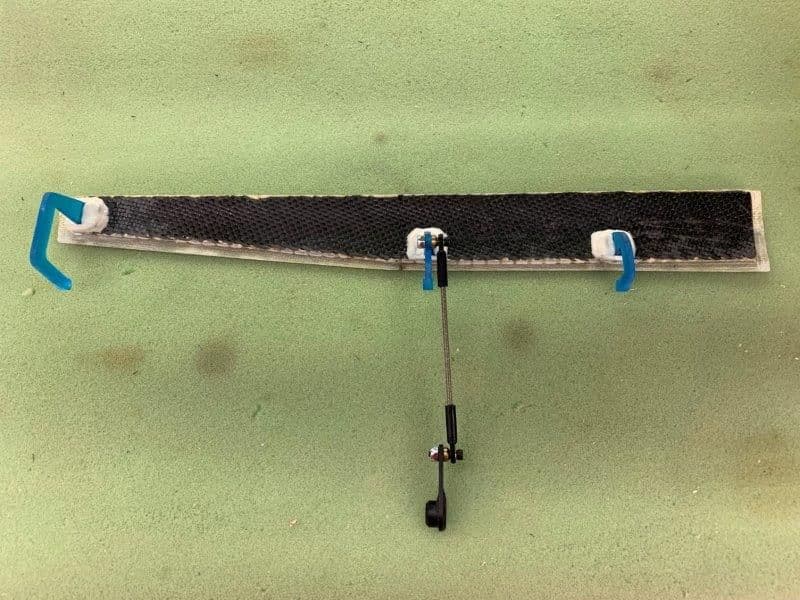
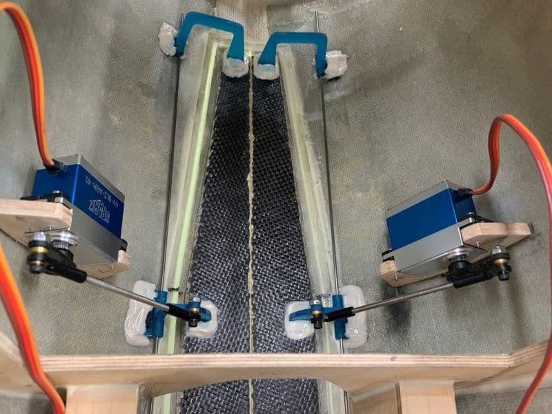
Here are the servos (or air valves if needed) that follow the blue bars. Now all I have to do is figure out how to build a chute system on top of the tail pipe!
Thanks again Dave for all your help and teaching.
Gary
Dave sent me an update and everything is working as designed. Its really a slick system and could have applications for more than just a drag chute. As my friend Frank said today....spoilers, speedbrakes, auto brakes, etc....
This screen shot shows just after a simulated landing with all deployment consent conditions armed and green but the ground speed is still above the high limit (shown in red) and the blue bars are in the closed pre-deployment positions. Note if desired, the jettison switch can be armed before landing but jettison will not occur until flaps are raised. No need to mess with another switch on landing roll or taxi back, just raise the flaps and the chute drops off.
This screen shot shows ground speed below the low limit in green and the blue bars on the right shows the chute door and deployment was commanded at the low limit of 18 mph. The door would be open and the chute would be out now.
This screen shot shows a simulated taxi back and my fingers just after raising the flaps with the jettison consent armed and green and the jettison blue bar is on the right. The chute would have been jettisioned when flaps were raised.
Here are the servos (or air valves if needed) that follow the blue bars. Now all I have to do is figure out how to build a chute system on top of the tail pipe!
Thanks again Dave for all your help and teaching.
Gary
09-16-2019, 05:53 PM
#462
Thread Starter
My Feedback: (20)
One more thing for the Jeti users, the C01, C02, C03 on the status page are the virtual switches that are created by the Lua apps. They must be assigned to the door, deploy, and jettison functions in the function assignment page under the Jeti model menu.
09-16-2019, 06:09 PM
#463
Thread Starter
My Feedback: (20)
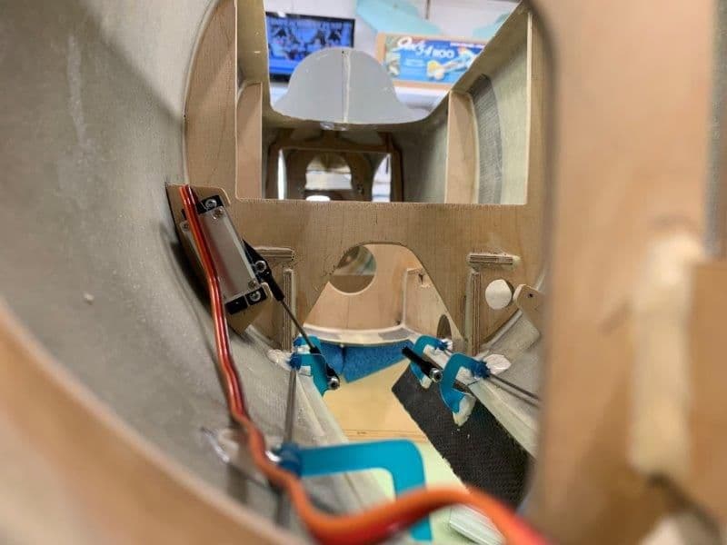
Meanwhile, back at the workbench I got some work done on the nose gear door servos
Dry fitting the servo inline with the middle nose gear door hinge
I wanted it to be below the bottom of the cockpit tub cut out on the former so as not to interfere with anything later
I used the corner of the servo in the middle of the former hole precision line up method...
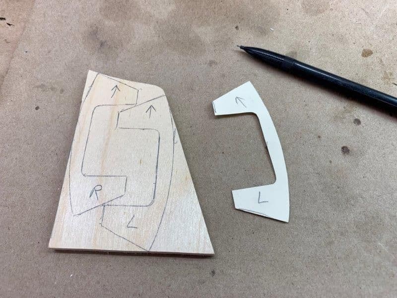
It looked good to me so how to make a mount with that curve on it?
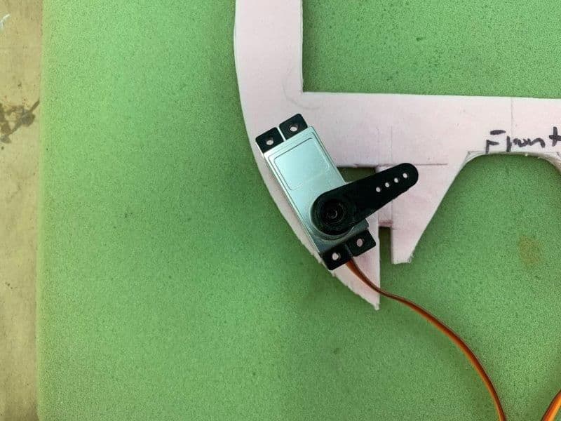
I remembered my pink foam pattern for the former, curve close enough!
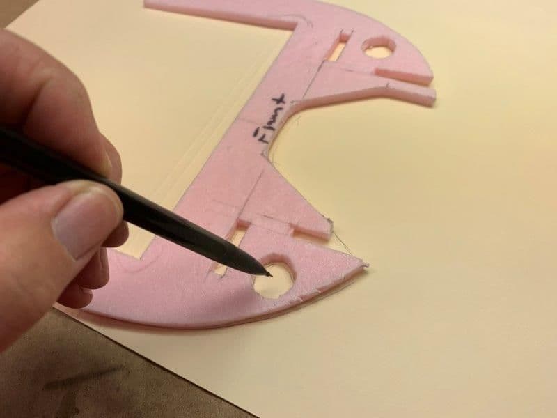
Traced former on file folder
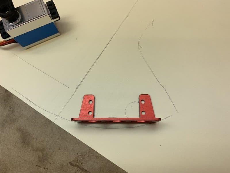
I used a metal servo mount for a pattern
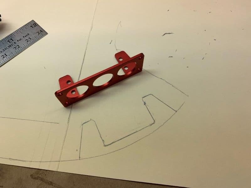
Final pattern after a little tracing and erasing

Pattern cut out and dry fit... looked good to me. The rest of the file folder became epoxy mixing cards!
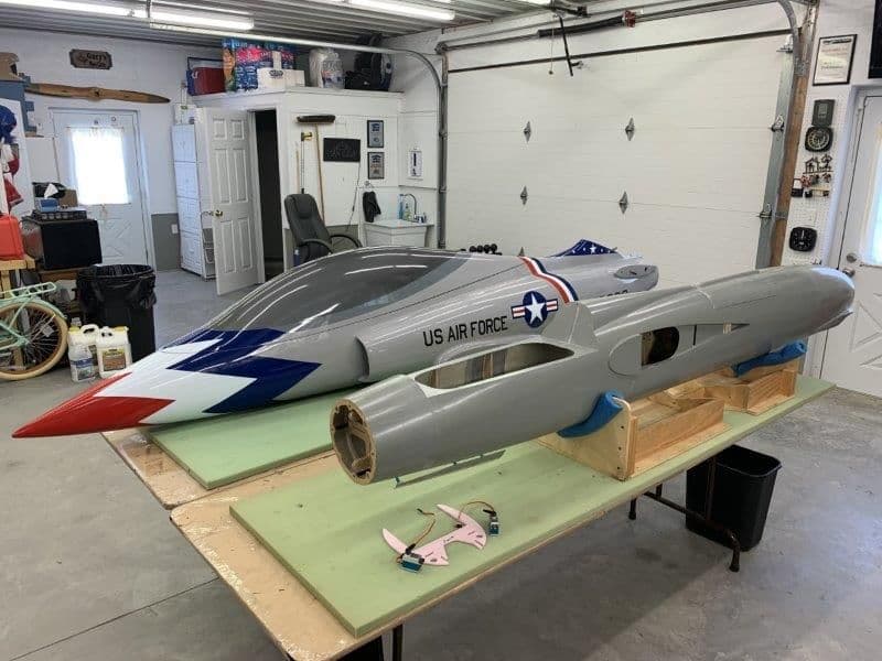
I thought the F-105 was big...till I put the Havoc next to it! This bigger stuff has reached my limit! I need a crew chief to help move them around!
Dry fitting the servo inline with the middle nose gear door hinge
I wanted it to be below the bottom of the cockpit tub cut out on the former so as not to interfere with anything later
I used the corner of the servo in the middle of the former hole precision line up method...
It looked good to me so how to make a mount with that curve on it?
I remembered my pink foam pattern for the former, curve close enough!
Traced former on file folder
I used a metal servo mount for a pattern
Final pattern after a little tracing and erasing
Pattern cut out and dry fit... looked good to me. The rest of the file folder became epoxy mixing cards!
I thought the F-105 was big...till I put the Havoc next to it! This bigger stuff has reached my limit! I need a crew chief to help move them around!
09-17-2019, 10:40 AM
#464
Thread Starter
My Feedback: (20)
Nose door servo mounts
I cut out the pattern and traced it on 1/4" plywood
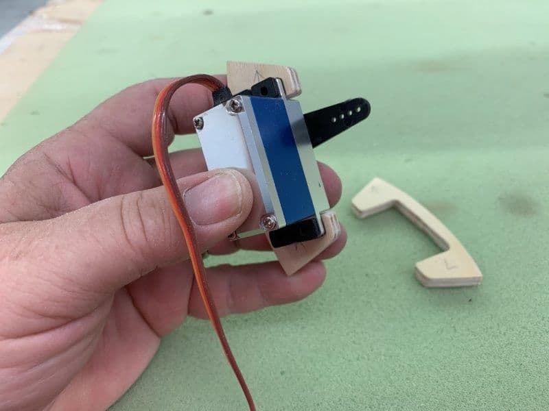
Plywood mounts cut on scroll saw and dry fit to servos
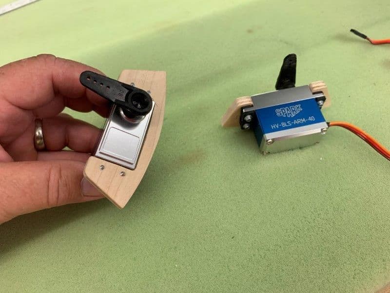
Holes drilled and servos screwed to mounts

I found that the top of the mounts were level with the cockpit tub cut out in the former for proper position
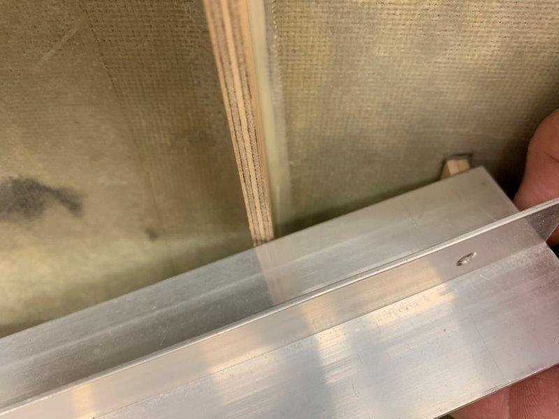
The servo mount was placed against the bottom of the aluminum T bar to set the level the same on both sides

Mount location traced
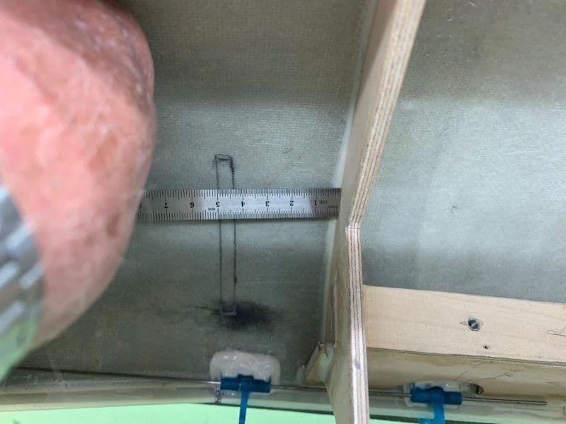
Measurements made to transfer to left side
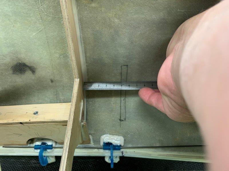
Left side measured and traced in place
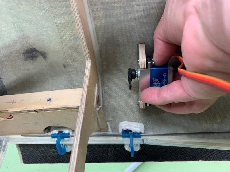
Left side servo dry fit into position
Servo mounts tacked in place with medium CA
I cut out the pattern and traced it on 1/4" plywood
Plywood mounts cut on scroll saw and dry fit to servos
Holes drilled and servos screwed to mounts
I found that the top of the mounts were level with the cockpit tub cut out in the former for proper position
The servo mount was placed against the bottom of the aluminum T bar to set the level the same on both sides
Mount location traced
Measurements made to transfer to left side
Left side measured and traced in place
Left side servo dry fit into position
Servo mounts tacked in place with medium CA
09-17-2019, 11:00 AM
#465

 09-17-2019, 01:03 PM
#467
Thread Starter
My Feedback: (20)
Good catch. I did move the right side 10mm forward after I took the photo because I did not account for the depth of the ball linkage. Both are set at 50mm from the former now. Thanks, I can use all the help I can get!
Gary
Gary
09-17-2019, 01:18 PM
#468
Thread Starter
My Feedback: (20)
I need to correct post #462 where I said C01, C02, C03 on the status page are the virtual switches. Talking with Dave today I learned these are Lua controls, different than virtual switches. They allow the Lua program to create a control like a stick or knob that is software controlled. They are found under the Apps button when you assign the control in the Jeti Function Assingment menu. Dave will have to explain more if you want to know.
09-17-2019, 05:18 PM
#469
Thread Starter
My Feedback: (20)
Setting up nose gear door linkage
Initial measurement for push rod was 50 mm. Later I made it 70mm so that the servo arm would not be aligned with the push rod in the open position. This made the door much stiffer when in the open position.
4-40 threaded rod push rods made up for each door with ball joints on each end
Initial setup turned out to be too short and I made the push rod 20mm longer in final the final install
With the servo arm aligned with the push rod the door open position was very spongy. You could move the door several degrees just from poor push rod geometry. This is when I made them 20mm longer.
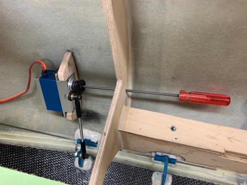
Small hole drilled in former to get ball driver in to tighten the servo arm bolt
Both sides installed.
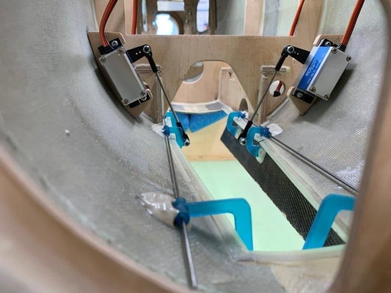
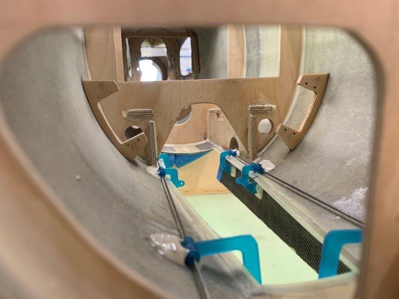
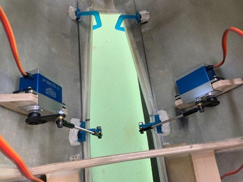
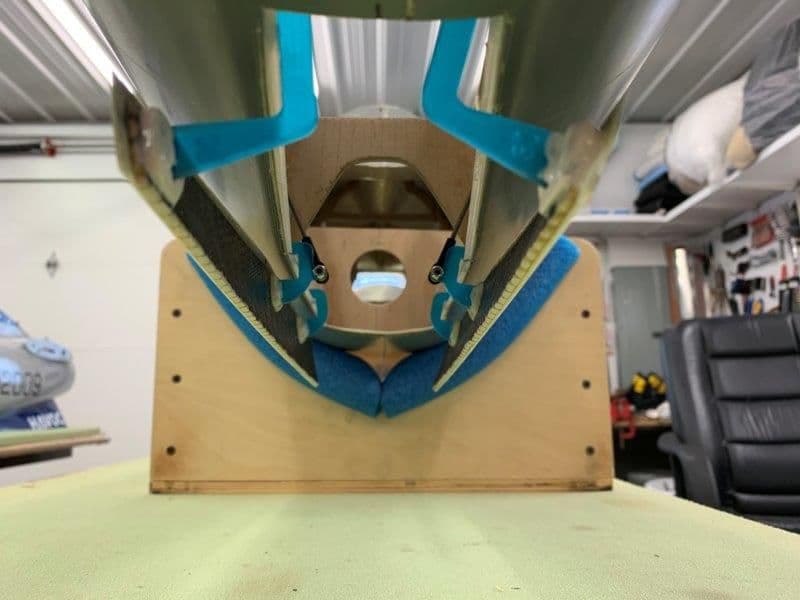
Front view when doors open. Longer push rods can be seen here and the door open position is much stiffer.
Front view with doors closed
View from top with doors closed. The hinge alignment wires will be replaced with 1.5mm bolts in the final install.
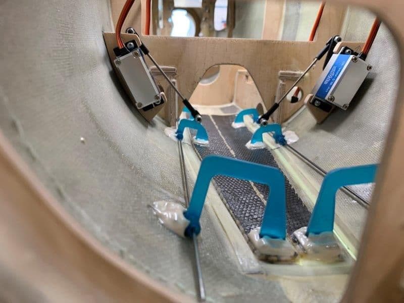
View from bottom with doors open.
Next work is main gear doors.
Initial measurement for push rod was 50 mm. Later I made it 70mm so that the servo arm would not be aligned with the push rod in the open position. This made the door much stiffer when in the open position.
4-40 threaded rod push rods made up for each door with ball joints on each end
Initial setup turned out to be too short and I made the push rod 20mm longer in final the final install
With the servo arm aligned with the push rod the door open position was very spongy. You could move the door several degrees just from poor push rod geometry. This is when I made them 20mm longer.
Small hole drilled in former to get ball driver in to tighten the servo arm bolt
Both sides installed.
Front view when doors open. Longer push rods can be seen here and the door open position is much stiffer.
Front view with doors closed
View from top with doors closed. The hinge alignment wires will be replaced with 1.5mm bolts in the final install.
View from bottom with doors open.
Next work is main gear doors.
09-18-2019, 05:19 AM
#470
 09-18-2019, 05:51 PM
#471
Thread Starter
My Feedback: (20)
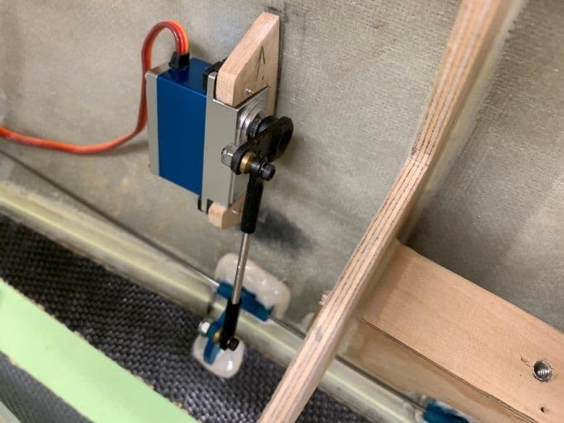
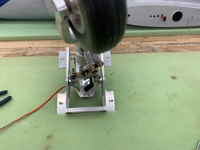
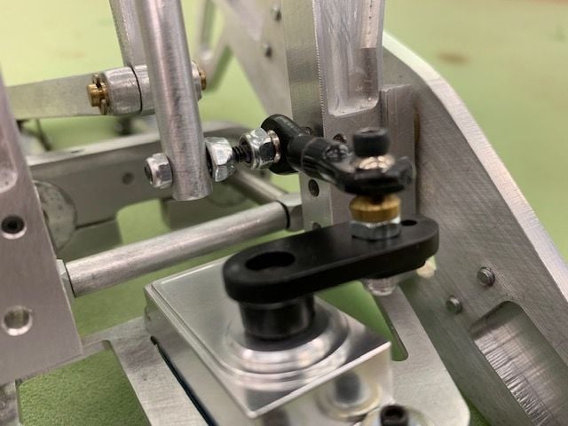
Nose gear steering servo and linkage.
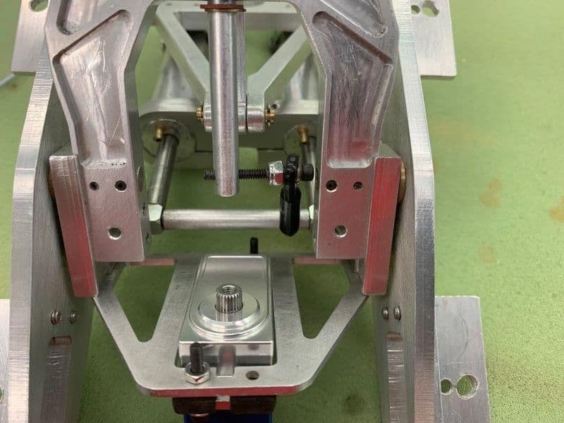
I finally mounted a servo in the NG using rubber grommets and added a ball joint to the 4-40 tiller bolt that was in the steering spindle
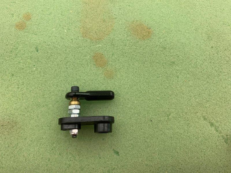
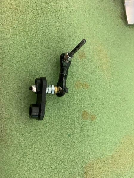
Next I found a heavy duty plastic arm with 25T spline in the spare parts drawer. I added a ball joint on a stack 4-40 nuts to raise the ball joint close to the level with the tiller arm. This did not look very good but its all I had to work with now.
There is a very short distance between the servo arm and the tiller bolt. I had to mark the ball joint sleeves to cut.
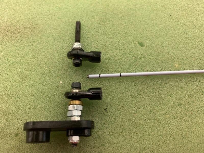
I had about 6mm depth of threads after cutting. The second mark was the original depth of the ball joint sleeve before cutting
I cut a 4-40 threaded rod to 10mm and screwed the ball joint sleeves together
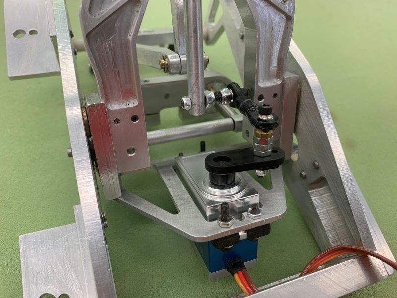
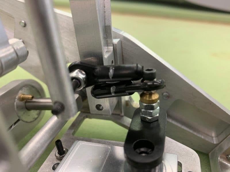
The final assembly was not very good. The biggest problem was flexing of the rubber grommets. The plastic arm also flexed. Add that to the built in flex of the servo mounting plate and the long spindle that the tiller is mounted in and the whole thing was a mess.
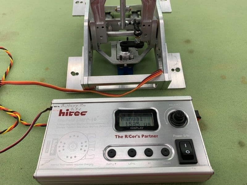
Servo tester was used to test the whole thing and it did not work very well.
I removed the rubber grommets and got rid of most of the slop in the linkage system
Tested left
And right
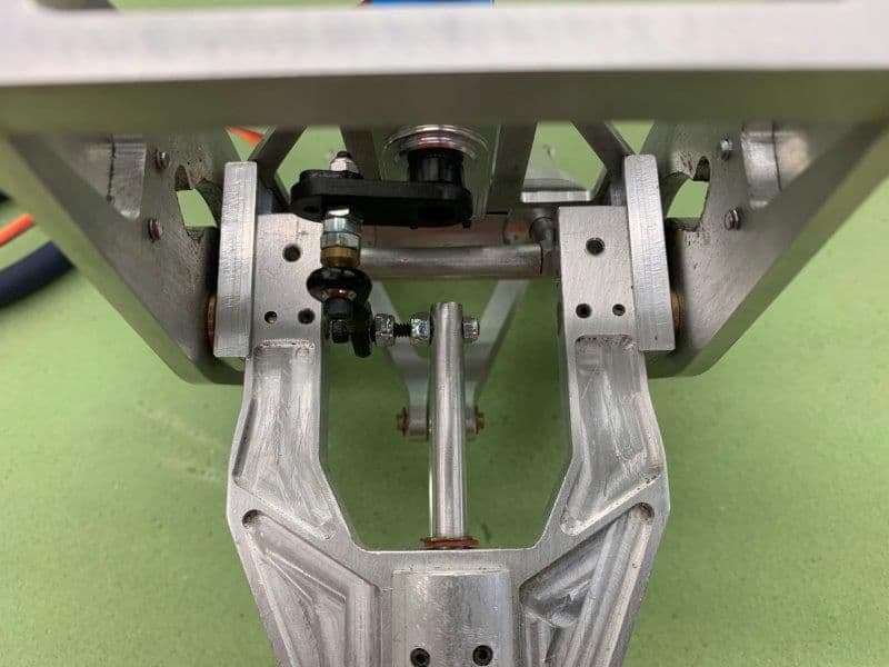
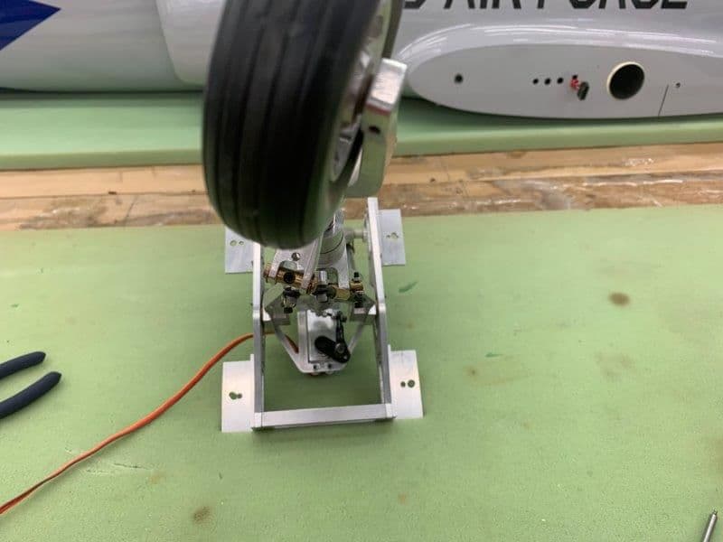
This is the long steering spindle that the tiller is mounted to and it also flexes when moved. I ordered some heavy duty metal 25T servo arms and hopefully that will stiffen up the whole system. More to come here...
I finally mounted a servo in the NG using rubber grommets and added a ball joint to the 4-40 tiller bolt that was in the steering spindle
Next I found a heavy duty plastic arm with 25T spline in the spare parts drawer. I added a ball joint on a stack 4-40 nuts to raise the ball joint close to the level with the tiller arm. This did not look very good but its all I had to work with now.
There is a very short distance between the servo arm and the tiller bolt. I had to mark the ball joint sleeves to cut.
I had about 6mm depth of threads after cutting. The second mark was the original depth of the ball joint sleeve before cutting
I cut a 4-40 threaded rod to 10mm and screwed the ball joint sleeves together
The final assembly was not very good. The biggest problem was flexing of the rubber grommets. The plastic arm also flexed. Add that to the built in flex of the servo mounting plate and the long spindle that the tiller is mounted in and the whole thing was a mess.
Servo tester was used to test the whole thing and it did not work very well.
I removed the rubber grommets and got rid of most of the slop in the linkage system
Tested left
And right
This is the long steering spindle that the tiller is mounted to and it also flexes when moved. I ordered some heavy duty metal 25T servo arms and hopefully that will stiffen up the whole system. More to come here...
09-19-2019, 05:35 PM
#474
Thread Starter
My Feedback: (20)
Well I said several times that I can use all the help I can get. So I got to shop this morning and saw Tim's post about mounting the servo on the other side of the bracket. Well, yesterday I tried several times to get it in on the other side and could not get it to fit in because of the spindle blocking the path into the mounting bracket. This morning because of Tim's comment I thougtht...wonder if I can take it apart and fit it in that way. So I picked the nose gear up this morning and turned it over and immediately felt like an idiot. All it took was removing 2 screws and off it came. I had just never thought of removing the mounting bracket yesterday and never look to see if it was possible. Duhh... Also I had seen pictures of how 2 other guys had done it and both mounted the servo on the bottom like i did before. I set the mental pre-conditons in my mind and never thought outside the box it put me in. So great to have other people looking it stuff and seeing better ways to do it. Thanks Tim.
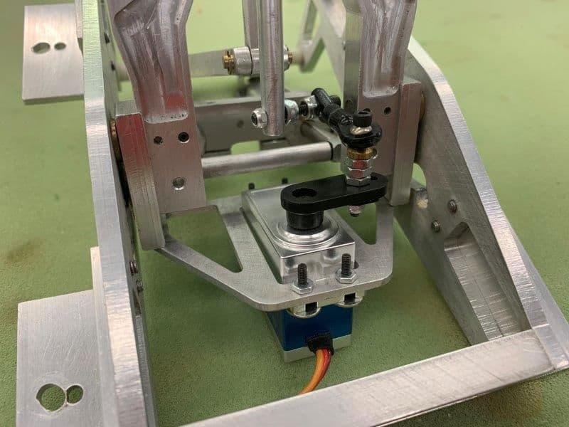
So in about 30 min. I I had it back together working much better than before. I was able to remove 2 nuts off the stack and that made the linkage much stiffer.

I flipped the gear over and it was easy to get to the mounting bracket screws.
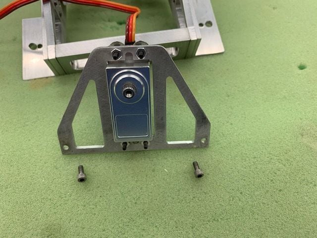
Just 2 screws and off came the servo mounting bracket.
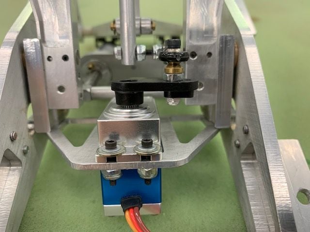
Servo mounted on top of bracket and 2 nuts came off the ball joint bolt
The linkage is much stiffer now and with a metal arm will be better.
And then this evening I saw the post by Auburn02. An even better idea! I now plan to use a pull pull ball joint setup on a metal dual servo horn. That should talk most of the movement out of the spindle and eliminate almost all the slop in the linkage. Thanks, Auburn02, another great idea. Now to order a dual servo arm.
Thanks, Gary
So in about 30 min. I I had it back together working much better than before. I was able to remove 2 nuts off the stack and that made the linkage much stiffer.
I flipped the gear over and it was easy to get to the mounting bracket screws.
Just 2 screws and off came the servo mounting bracket.
Servo mounted on top of bracket and 2 nuts came off the ball joint bolt
The linkage is much stiffer now and with a metal arm will be better.
And then this evening I saw the post by Auburn02. An even better idea! I now plan to use a pull pull ball joint setup on a metal dual servo horn. That should talk most of the movement out of the spindle and eliminate almost all the slop in the linkage. Thanks, Auburn02, another great idea. Now to order a dual servo arm.
Thanks, Gary
Last edited by Viper1GJ; 09-19-2019 at 05:41 PM.
09-22-2019, 06:07 AM
#475
Thread Starter
My Feedback: (20)
Main landing gear inner doors
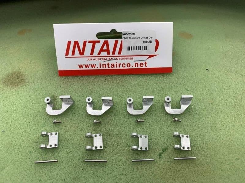
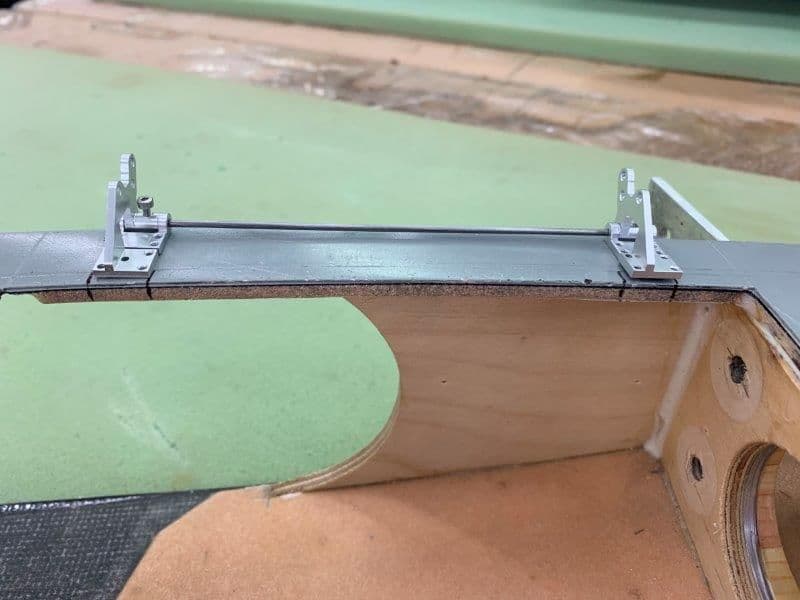
I elected to use these metal offset hinges I got from Dreamworks. The hinge pins are held in by small set screws
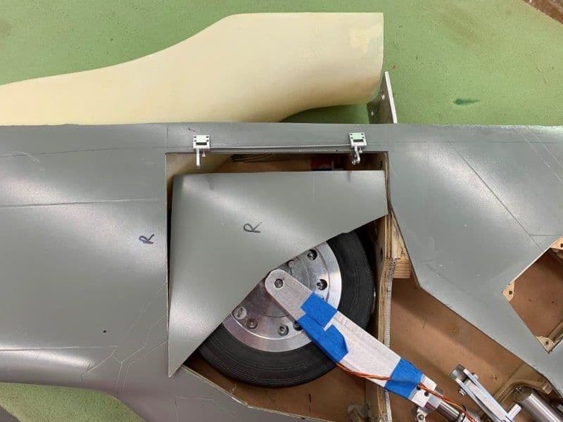
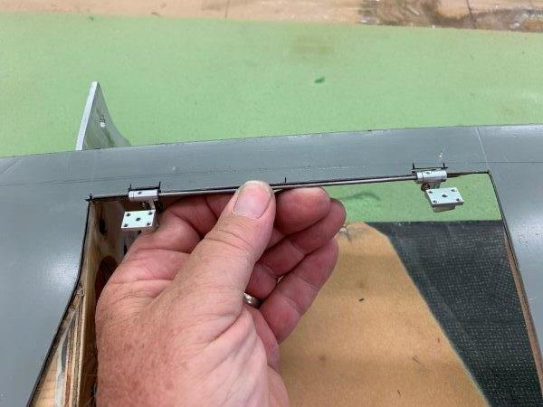
Rough layout of gear door parts to see if locations will clear all the other parts
Servo below wheel is OK and hinges clear wheel in intake duct
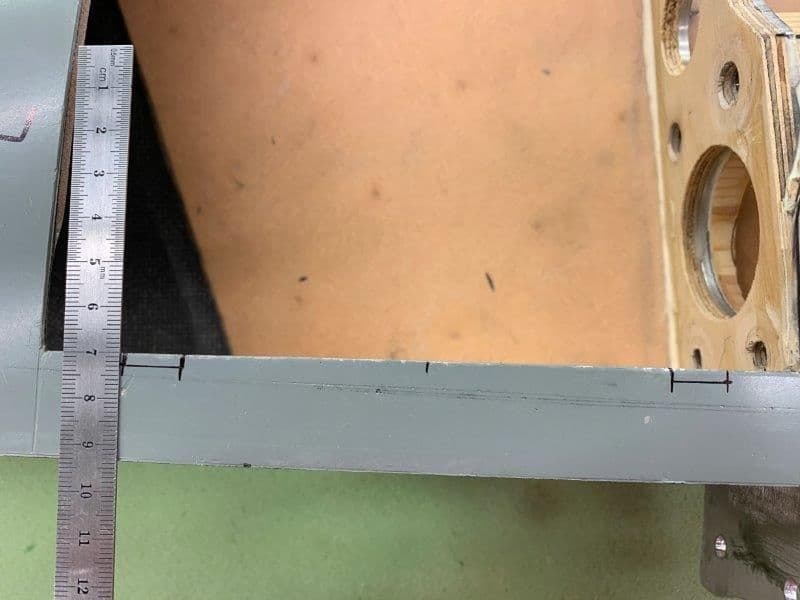
HInge locations selected and marked
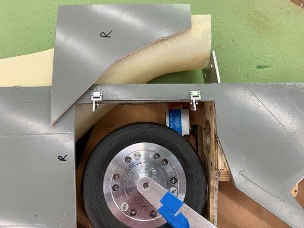
Inside edges marked for material removal to allow inside hinge half to fold under the outer skin
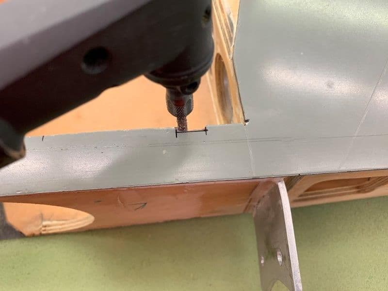
Small perma grit cutter used to rough out the hinge cutout
Permagrit flat file used to square the cut
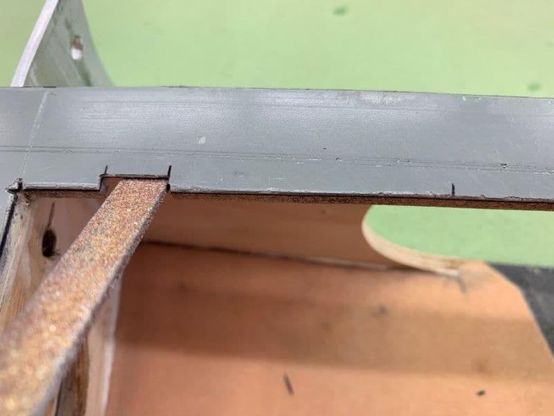
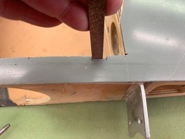
Foam material removed under cut out to allow the inside hinge half to lay almost flat against the outer skin
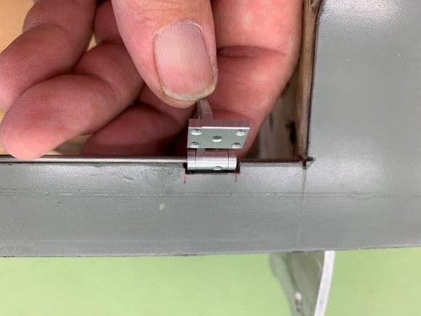
HInges centered in the cut out
HInge alignment wire has to be at the outside edge of wing skin to allow door to swing over the curved surface
I elected to use these metal offset hinges I got from Dreamworks. The hinge pins are held in by small set screws
Rough layout of gear door parts to see if locations will clear all the other parts
Servo below wheel is OK and hinges clear wheel in intake duct
HInge locations selected and marked
Inside edges marked for material removal to allow inside hinge half to fold under the outer skin
Small perma grit cutter used to rough out the hinge cutout
Permagrit flat file used to square the cut
Foam material removed under cut out to allow the inside hinge half to lay almost flat against the outer skin
HInges centered in the cut out
HInge alignment wire has to be at the outside edge of wing skin to allow door to swing over the curved surface