1/6 F-105 Build Thread
 05-21-2019, 06:57 PM
#426

Thread Starter
My Feedback: (20)
I talked to James at Esprit RC about using the logic switches in the DS-24 and he said it should be fairly easy to do and the Mrpm hall sensor was very accurate and rpm could easily be converted to mph based on wheel size. I will give it some more thought and talk to Frank about how his D4S system works.
Gary
Gary
 05-23-2019, 03:51 AM
#427


Gary,
Not sure how you would use the hall effect sensor for wheel speed, as you would have to be counting pulses as the wheel rotates. I guess you could do some LUA programming, but not sure of any other way it would work.
I considered a micro-switch for a Weight-On-Wheels interlock for my Hunter drag chute after I had an inadvertent deployment on finals at about 10ft AGL that almost destroyed the model. In the end I opted to replace my standard Jeti 3-position switch I used for the chute (closed/ deploy/ release) with a 3-position locking switch I bought off of e-bay and soldered onto the little switch board. Now I have to lift the switch over the lock to deploy and release the chute.
It does look cool to deploy the chute at about 1-2ft in the flare.
The build looks good - keep going.
Paul
KISS it guys, KISS it. LOL
")
 07-13-2019, 05:56 PM
#429
Thread Starter
My Feedback: (20)
Hey Mark,
Thanks for checking in. The F-105 got sidelined in May for the summer flying season. I've attended several meets and fly-ins but have not done any more work to the F-105 since May. I have been working with Dave ( ww2birds) on a drag chute Lua program for the Jeti DS-24. He has written a cool Lua program with several safety interlocks to prevent accidental deployment of the drag chute. Dave posted a thread about it here in the Jet forum. I have it working on the bench and operating three servos on the proper sequence, door open, chute deploy, and chute release. I am sending him my landing gear and he will design and 3D print a bracket to hold the wheel RPM sensor on the landing gear.
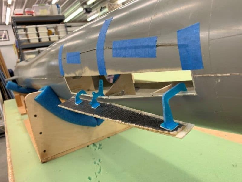
I bought a pre-owned Havoc at Joe Nall and am currently refitting it and hope to get it flying by the end of July. I plan to use the Havoc to run in the K-320 turbine, test the drag chute program, and just learn how to operate the drag chute. Never used one before. My plan is to make a drag chute "pod" that will fit between the Havoc ventral fins on the bottom of the fuse and test the drag chute system.
My wife has me going on a "before back to school trip" with the grand kids in August and after that I plan to get back to working on the F-105 again. Hopefully some more progress by the Georgia Super Jets South meet in September.
Thanks,
Gary
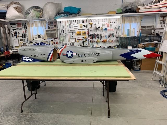
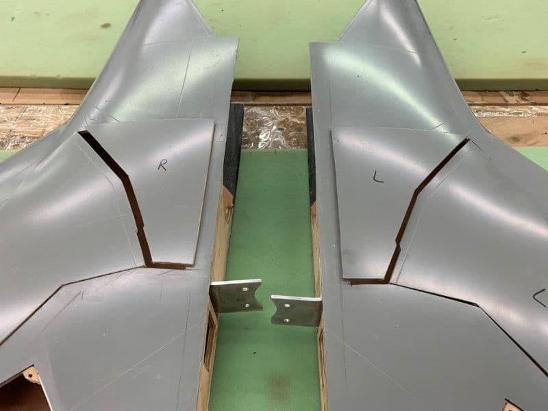
F-105 fuse in the holding pattern for the summer.
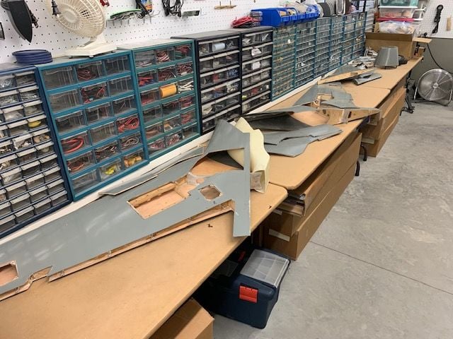
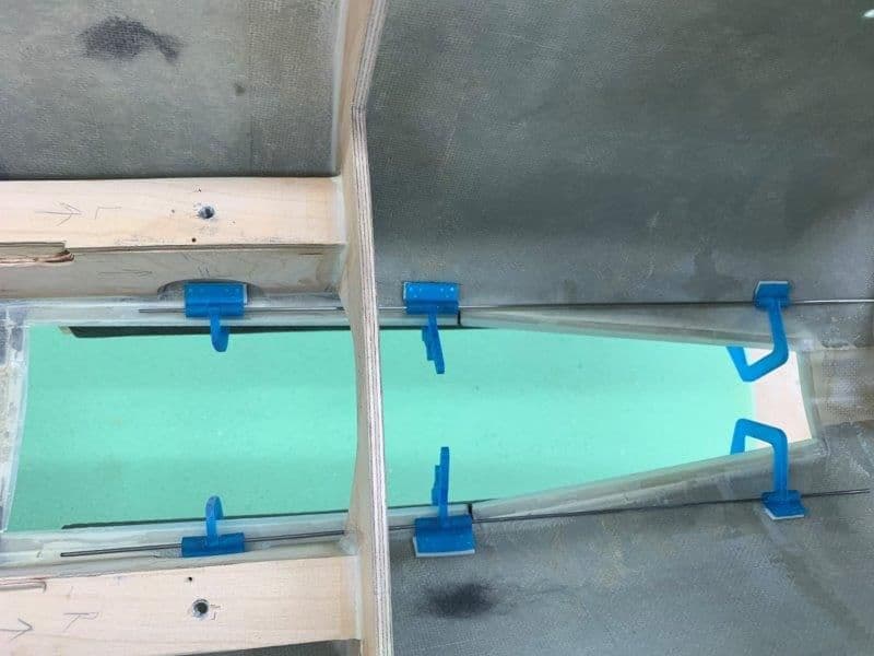
Wings waiting for gear door fitting
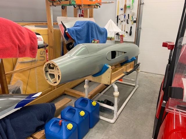
Havoc fuse getting refitted with new stuff and K-320 turbine
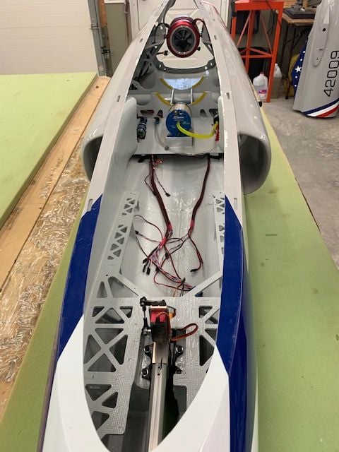
The inside of the Havoc had a well used look, so I painted it. Pieces and parts now going in, hope to fly it by end of July. Then set up a drag chute test pod.
Thanks for checking in. The F-105 got sidelined in May for the summer flying season. I've attended several meets and fly-ins but have not done any more work to the F-105 since May. I have been working with Dave ( ww2birds) on a drag chute Lua program for the Jeti DS-24. He has written a cool Lua program with several safety interlocks to prevent accidental deployment of the drag chute. Dave posted a thread about it here in the Jet forum. I have it working on the bench and operating three servos on the proper sequence, door open, chute deploy, and chute release. I am sending him my landing gear and he will design and 3D print a bracket to hold the wheel RPM sensor on the landing gear.
I bought a pre-owned Havoc at Joe Nall and am currently refitting it and hope to get it flying by the end of July. I plan to use the Havoc to run in the K-320 turbine, test the drag chute program, and just learn how to operate the drag chute. Never used one before. My plan is to make a drag chute "pod" that will fit between the Havoc ventral fins on the bottom of the fuse and test the drag chute system.
My wife has me going on a "before back to school trip" with the grand kids in August and after that I plan to get back to working on the F-105 again. Hopefully some more progress by the Georgia Super Jets South meet in September.
Thanks,
Gary
F-105 fuse in the holding pattern for the summer.
Wings waiting for gear door fitting
Havoc fuse getting refitted with new stuff and K-320 turbine
The inside of the Havoc had a well used look, so I painted it. Pieces and parts now going in, hope to fly it by end of July. Then set up a drag chute test pod.
08-28-2019, 05:31 PM
#430
Thread Starter
My Feedback: (20)
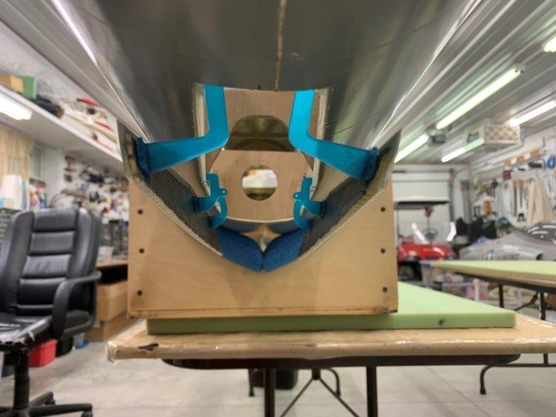
After about 3 1/2 months of layoff, I finally got back to the F-105 this week. It's been since May since the last work. Over the summer Dave got a neat drag chute Lua program done and it is working well on the bench. I sent Dave my main landing gear so he could fit a Jeti Mrpm sensor to the wheels to determine ground speed during landing roll to use in the drag chute deployment. I started to work on the main gear doors but stopped when I needed to use the gear to determine the best location of the door hinges and servo. I am currently planning on using servos to actuate the gear doors so I needed to make sure there was clearance between the servo mounts and the main gear tires in the wheel well. So without the main gear on hand I stopped work there and went to the nose gear doors.

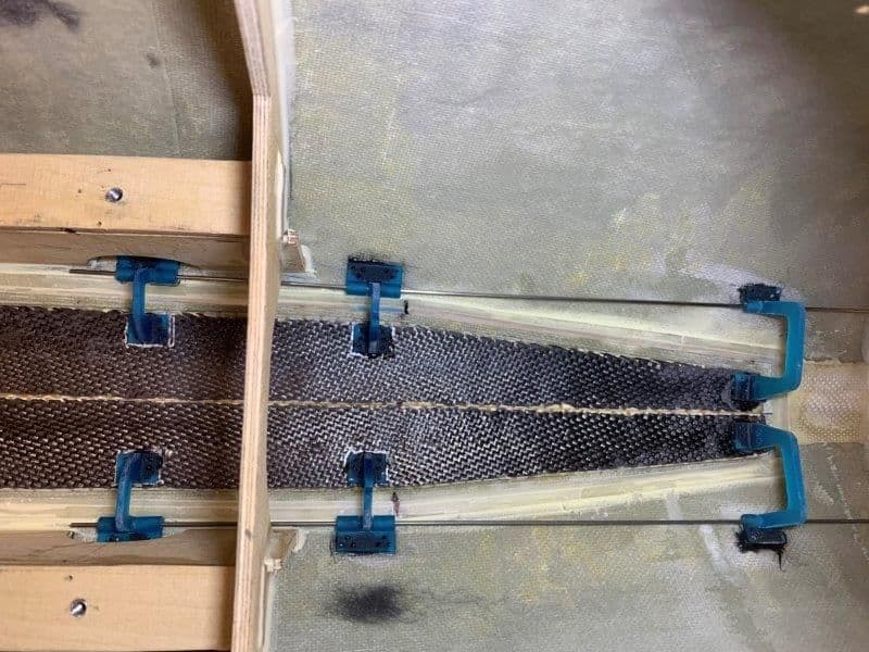
Gear doors and hinges
Hinge layout concept
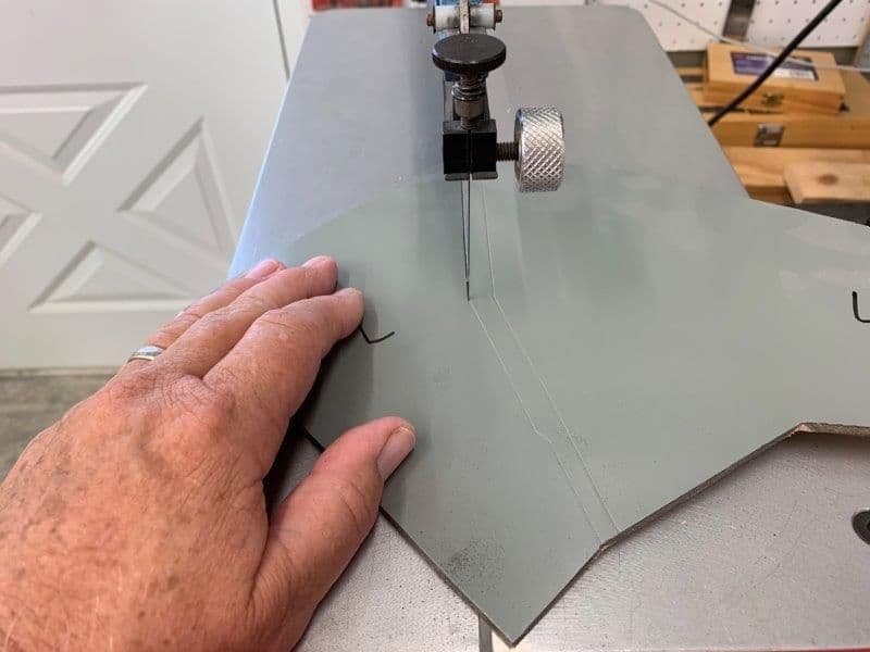
Main gear inner doors cut off from main doors
This is where I stopped on the main doors because the main gear is not available for dry fitting door hinges and servo
Gear doors and hinges
Hinge layout concept
Main gear inner doors cut off from main doors
This is where I stopped on the main doors because the main gear is not available for dry fitting door hinges and servo
08-28-2019, 05:42 PM
#431
Thread Starter
My Feedback: (20)
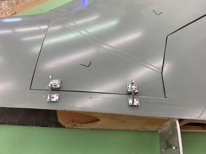
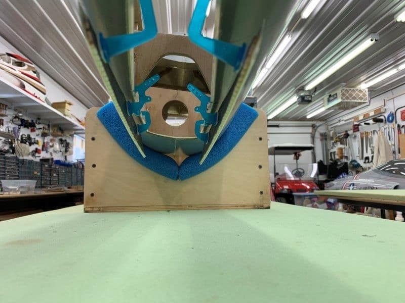
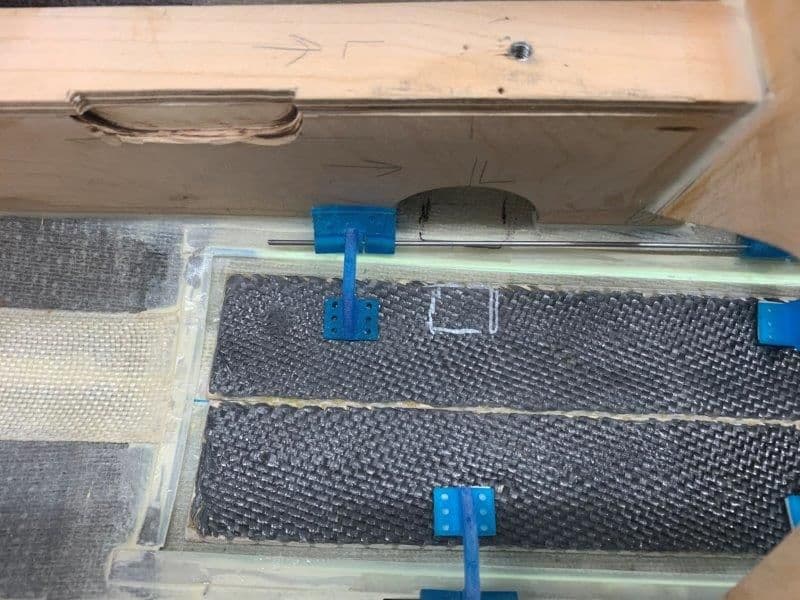
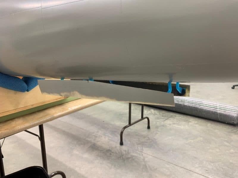
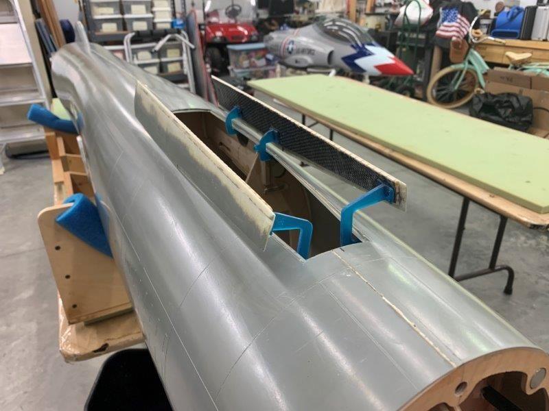
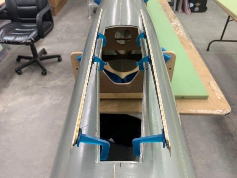
Switched to nose gear doors since main gear doors could not be completed until the main gear is available again.

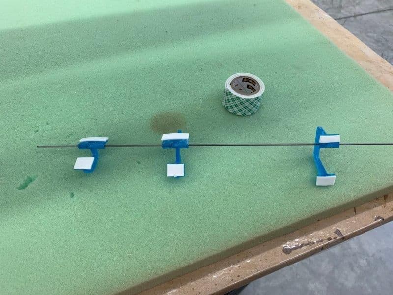
Nose gear doors taped in position and hinges pushed on the layout wire
Double sided mounting tape attached to offset door hinges
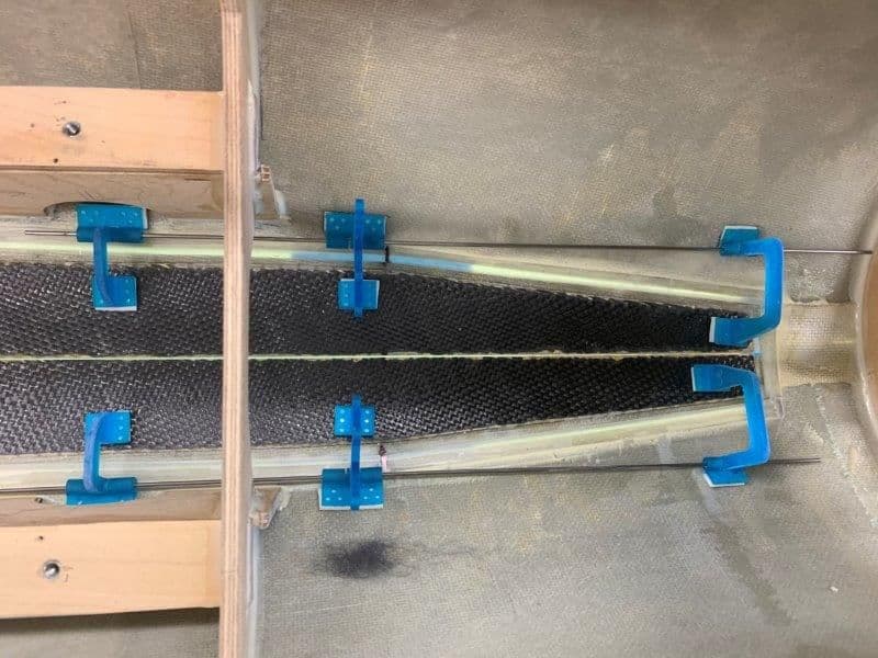
Both sides dry fit with mounting tape to test layout
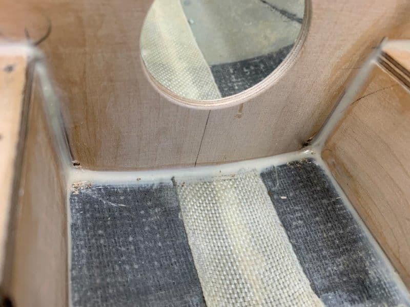
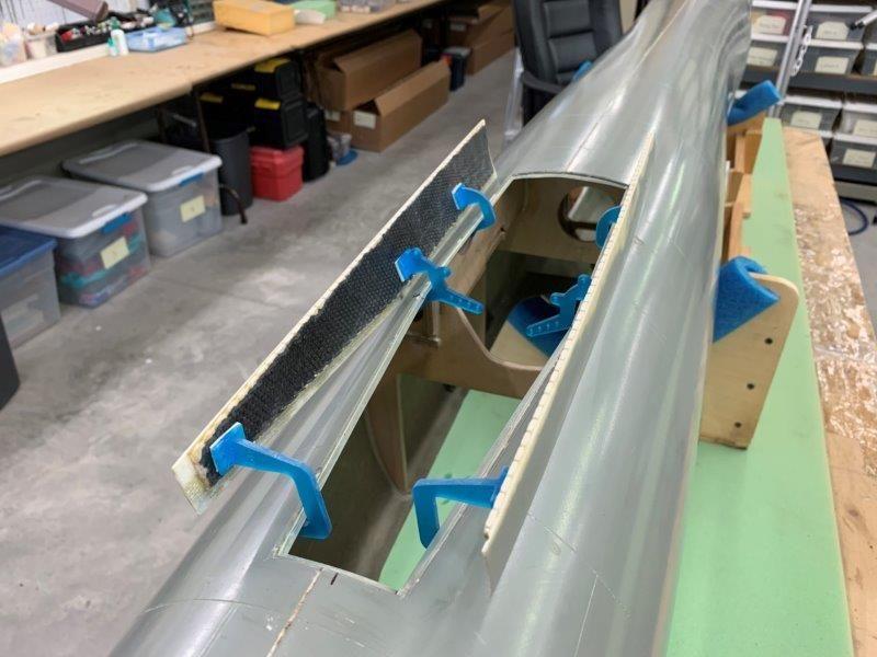
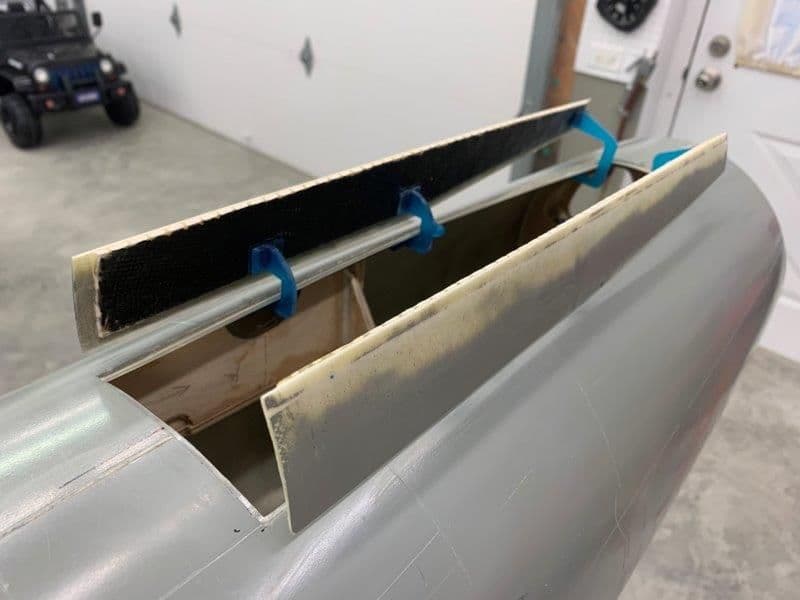
I had to drill two relief holes in order to remove the wires after fitting hinges in place
Left side tested after mock up of hinges
Both nose gear doors seem to work ok.
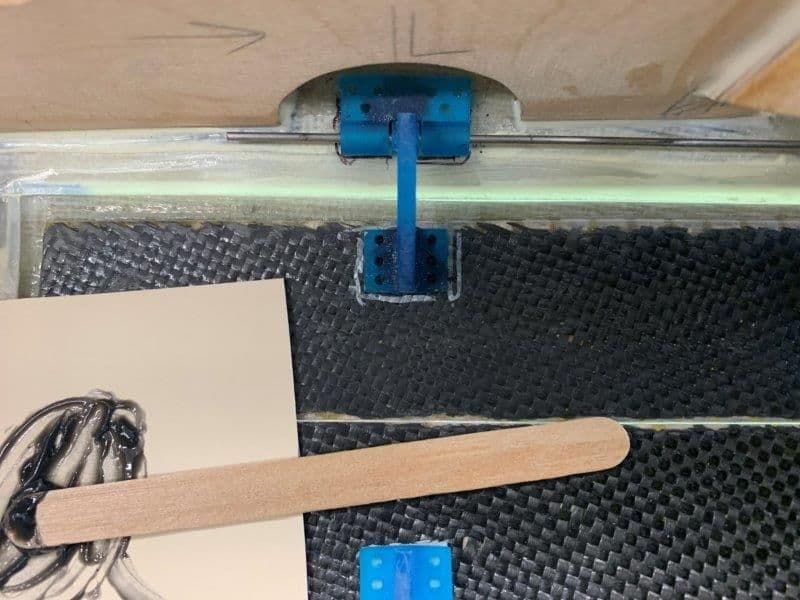
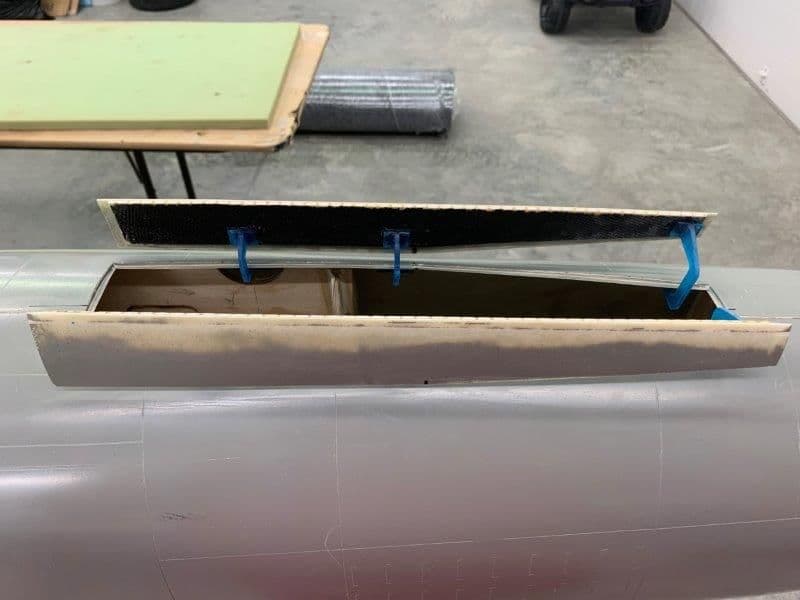
Bottom view of mock up. I determined the best servo attach point is the center lug of the center offset hinge. The other lug will be removed.
Up side down view
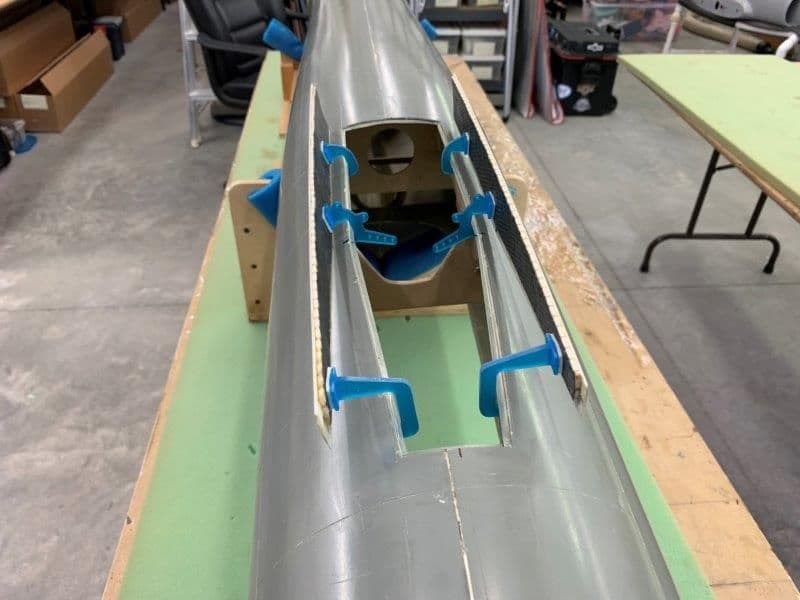
Ready to tack glue hinges in place
Nose gear doors taped in position and hinges pushed on the layout wire
Double sided mounting tape attached to offset door hinges
Both sides dry fit with mounting tape to test layout
I had to drill two relief holes in order to remove the wires after fitting hinges in place
Left side tested after mock up of hinges
Both nose gear doors seem to work ok.
Bottom view of mock up. I determined the best servo attach point is the center lug of the center offset hinge. The other lug will be removed.
Up side down view
Ready to tack glue hinges in place
Last edited by Viper1GJ; 08-28-2019 at 05:44 PM.
08-28-2019, 06:02 PM
#432
Thread Starter
My Feedback: (20)
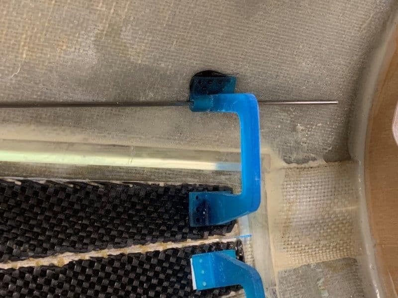
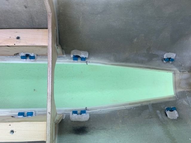
Offset hinges were tack glued onto the fuse and doors with Digipoxy 5min MMA from Danny at Aeropanda.com.
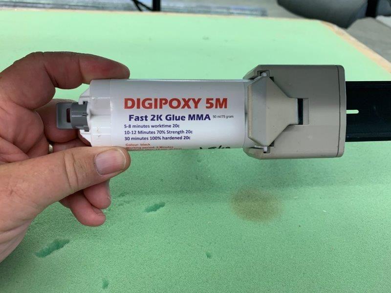
I started using this MMA this summer and found it to be real good for quick set up and fast cure. I found it to start setting in about 3 min and be firm after about 10 min. Full cure in about 30 min. It was real good at setting the offset hinges. There were 6 of them and each one had to be done one at a time. The plan is to secure the hinge bases with hysol after proper operation is ensured.
The technique was to move each hinge off center and apply the MMA glue. Then place the hinge back in place and let it set up.
I did the rear hinge first and then the front hinge. This allowed the middle hinge to free float to the proper position on the lay out wire and then glued into proper position.
Due to the curve of the fuse and door shape the flat hinge base did not fit level and the MMA allowed them to set at an angle. The space under the base will be filled with hysol after all is check out and working correctly.
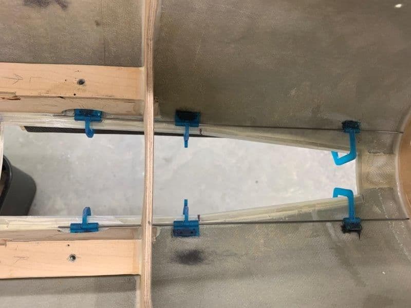
Both sides tacked up and working ok....except for the nose gear tire touching the front hinges when retracted, even after my CAREFUL placing of the hinge near the front of the doors. Translated...that means I forgot to check it at all and had to remove the front hinges and move them to the VERY front of the doors!
Now it works OK!
I started using this MMA this summer and found it to be real good for quick set up and fast cure. I found it to start setting in about 3 min and be firm after about 10 min. Full cure in about 30 min. It was real good at setting the offset hinges. There were 6 of them and each one had to be done one at a time. The plan is to secure the hinge bases with hysol after proper operation is ensured.
The technique was to move each hinge off center and apply the MMA glue. Then place the hinge back in place and let it set up.
I did the rear hinge first and then the front hinge. This allowed the middle hinge to free float to the proper position on the lay out wire and then glued into proper position.
Due to the curve of the fuse and door shape the flat hinge base did not fit level and the MMA allowed them to set at an angle. The space under the base will be filled with hysol after all is check out and working correctly.
Both sides tacked up and working ok....except for the nose gear tire touching the front hinges when retracted, even after my CAREFUL placing of the hinge near the front of the doors. Translated...that means I forgot to check it at all and had to remove the front hinges and move them to the VERY front of the doors!
Now it works OK!
Last edited by Viper1GJ; 08-28-2019 at 06:59 PM.
 08-29-2019, 05:09 AM
#435
Thread Starter
My Feedback: (20)
I don’t know what it is made from. It’s the same material that the smaller ones are made of. They are 3D printed. It is somewhat flexible and not brittle like most 3D printed stuff. You could send Oli an email and get more info.
Here is the link for them.
https://www.ultimate-jets.net/products/ultimate-offset-hinges?_pos=1&_sid=0b0ec2d55&_ss=r
Gary
Here is the link for them.
https://www.ultimate-jets.net/products/ultimate-offset-hinges?_pos=1&_sid=0b0ec2d55&_ss=r
Gary
Last edited by Viper1GJ; 08-29-2019 at 04:50 PM.

 08-31-2019, 05:34 PM
#438
Thread Starter
My Feedback: (20)
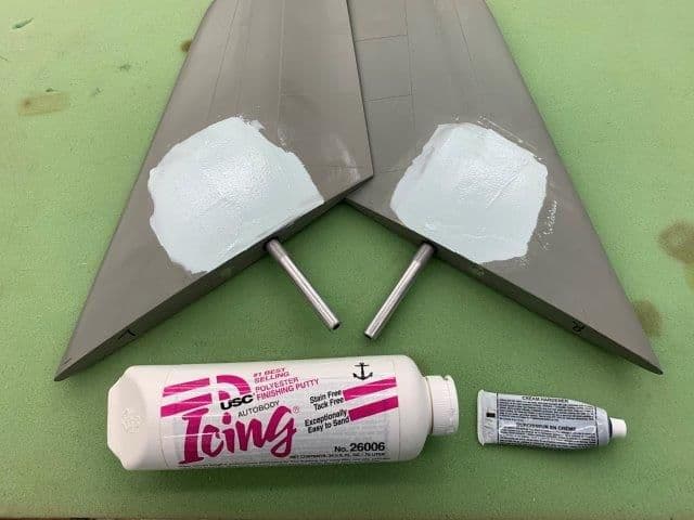
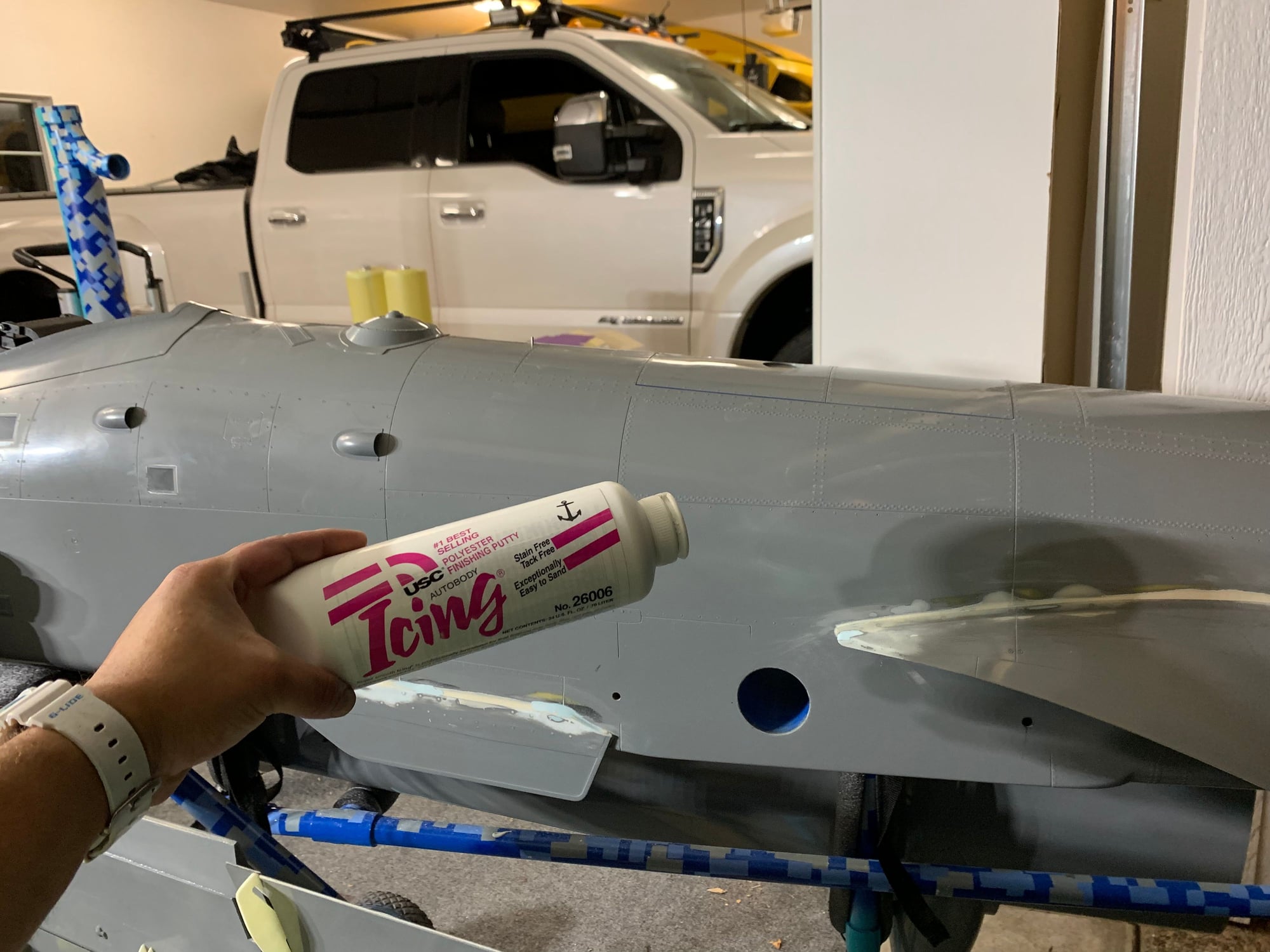
I think you are asking about this stuff. It's Icing polyester finishing putty. A friend who did lots of auto body work told me about it. I got it from Amazon.
Its polyester like Bondo but much lighter. It sands easy and is very easy to use. I usually mix it on a piece of card stock with a popsicle stick and spread with a small putty knife. Just a small dab of hardner is mixed in and you spread it immediately. It usually sets up in about 3 mins and hardens in bout 15 min. I can sand it after that.

 09-03-2019, 05:06 PM
#442
Thread Starter
My Feedback: (20)
Skunk, thanks for following the thread and the compliment. I was hoping to get to it again this week but have been overcome by hurricane Dorian prep. Probably will be next week after the storm passes before I can get back to it again. We are about 40 miles inland so no evac or flooding threat here but we will probably loose power due to winds. Hopefully we will not have any damage but we usually loose power due to trees and tree limbs cutting the lines.
Its been a little more than a year since I got started and I can see how the rest of it will go. Just need to pour the time into it. I hope to get back to it full time after the fall jet meets are over.
Thanks, Gary
Its been a little more than a year since I got started and I can see how the rest of it will go. Just need to pour the time into it. I hope to get back to it full time after the fall jet meets are over.
Thanks, Gary
09-03-2019, 07:24 PM
#444
 09-08-2019, 04:41 PM
#446
Thread Starter
My Feedback: (20)
Ravill, awesome. I felt the same when my friend Keith told me about it. The A-10 project looks great. Keep posting photos.
Thanks,
Gary
Thanks,
Gary
Last edited by Viper1GJ; 09-08-2019 at 04:43 PM.
09-13-2019, 01:33 PM
#447
Thread Starter
My Feedback: (20)
I sent Dave my main landing gears so he could design a mounting system for the Jeti Mrpm sensor so the drag chute Lua program can tell the wheel speed is on landing to deploy the drag chute. These are the photos he sent me of his design and software update for the drag chute Lua program.
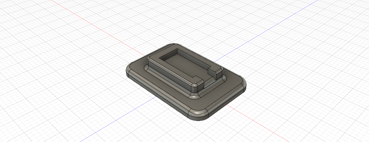
CAD design of sensor mounting plate on main gear strut. Dave says he designed them with Fusion 360 and printed them on an Ultimaker S5 with metallic silver PVA plastic. Each part took about 10 mins to print.
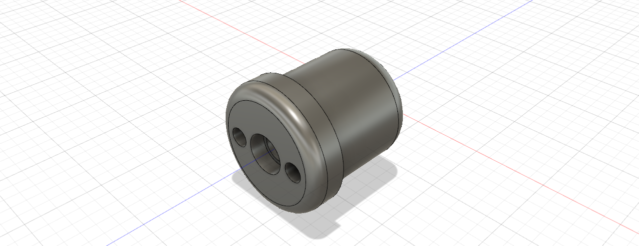
CAD file for magnet holder mounted in wheel.
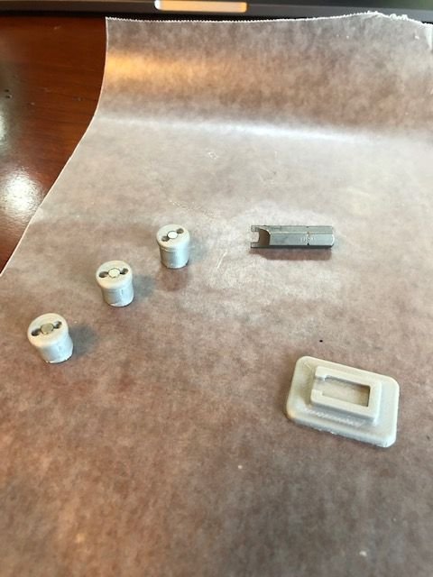
Parts 3D printed. The magnets are epoxied to the mounts. The spanner driver bit is used to screw the magnet mounts on to the wheel
Mrpm sensor glued into the mounting base
Dave's design was ingenious. It used the bolts that hold the wheel halves together. They stick out enough to screw the magnet mounts down on. What a great idea and parts design.
Magnets are glued into the mounts before they are screwed into the wheel
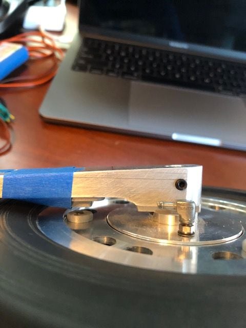
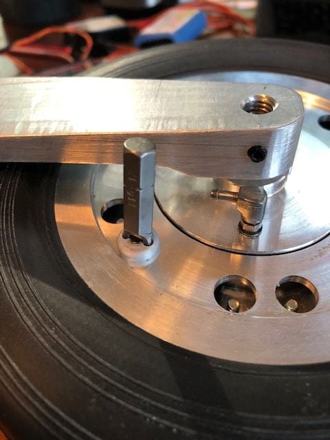
The sensor gets glued to the inside of the strut and gets pulses from the magnets during rotation. Sensor will be glued to strut using Goop, E6000, or similar soft glue so it could be removed if needed.
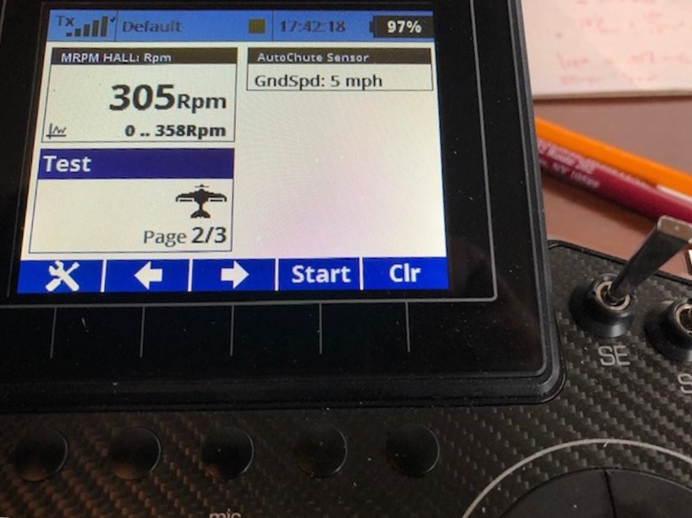
Screen shot of RPM and speed in Lua program. I have not seen the updated Lua yet but Dave had programmed it so the deploy speed is selectable. More to come on this when I get the gear back and see the new Lua program. Dave said it's mesmerizing to spin the wheel and watch the telemetry screens show RPM and MPH!
CAD design of sensor mounting plate on main gear strut. Dave says he designed them with Fusion 360 and printed them on an Ultimaker S5 with metallic silver PVA plastic. Each part took about 10 mins to print.
CAD file for magnet holder mounted in wheel.
Parts 3D printed. The magnets are epoxied to the mounts. The spanner driver bit is used to screw the magnet mounts on to the wheel
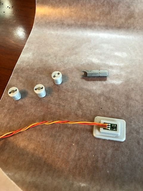
Mrpm sensor glued into the mounting base
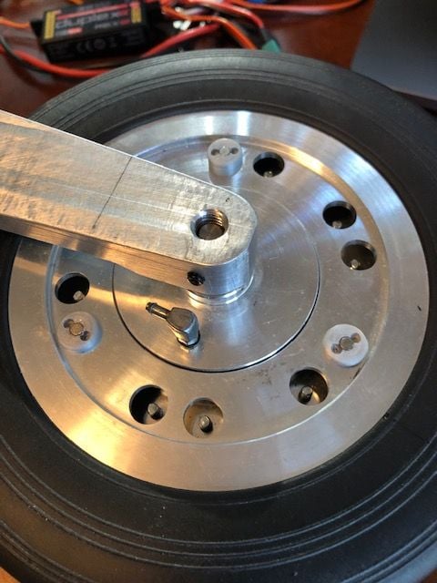
Dave's design was ingenious. It used the bolts that hold the wheel halves together. They stick out enough to screw the magnet mounts down on. What a great idea and parts design.
Magnets are glued into the mounts before they are screwed into the wheel
The sensor gets glued to the inside of the strut and gets pulses from the magnets during rotation. Sensor will be glued to strut using Goop, E6000, or similar soft glue so it could be removed if needed.
Screen shot of RPM and speed in Lua program. I have not seen the updated Lua yet but Dave had programmed it so the deploy speed is selectable. More to come on this when I get the gear back and see the new Lua program. Dave said it's mesmerizing to spin the wheel and watch the telemetry screens show RPM and MPH!
Last edited by Viper1GJ; 09-13-2019 at 01:46 PM.