


1/6 F-105 Build Thread

 04-20-2019, 07:35 PM
#402

Thomas, thanks for the info. Its at least 1/8 to 3/16" thick. It has allowed me to sand and shape the flaps and ailerons to fit the wing with out cutting through because its so thick. It real strong but I suspect its heavy also. Anyway the parts are very strong and stiff so it does work.
How is your T-38 coming along?
Gary
How is your T-38 coming along?
Gary
a little bit of a setback on the T38. I found out just after finishing printing all of the plugs the calibration was off in 2 axis� on the printer. At first it seemed they were off less than 1/8� in both of the directions, but after recalibrating it and getting a contract job completed, i printed a new set of flaps due to a design change and realized the original error was far worse than expected..
soo i�m having to reprint the entire airframe all over. If if wasnt for all the CAD work i have done for the fully ducted turbine installation and all of the prefab work for the structures, i could of made do... its a $400 error, but the print quality i have gotten after 100kg�s of printing on this printer has improved drastically and will end up saving time and money.
So physical progress is non existent, but the vast majority of the CAD modeling is done. All that is left is the cockpit, landing gear struts and some secondary structures for radio and turbine equipment mounting.
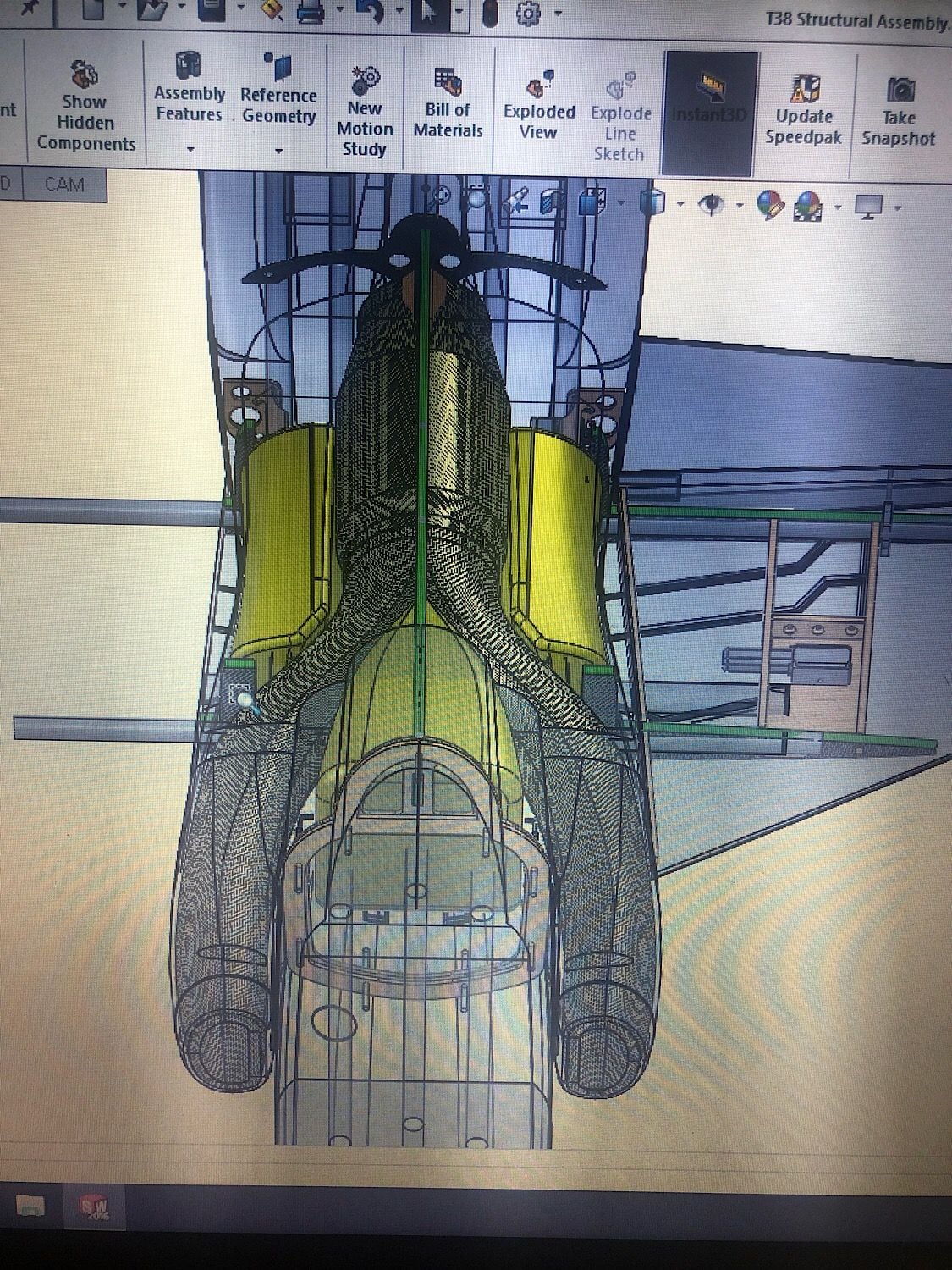
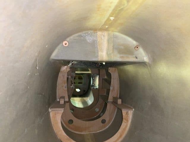
here�s a photo of the turbine install.
 05-08-2019, 05:25 PM
#403

Thread Starter
My Feedback: (20)
I finally got back to the F-105 build today after a few week delay working on other stuff, mostly not RC projects. Boo.
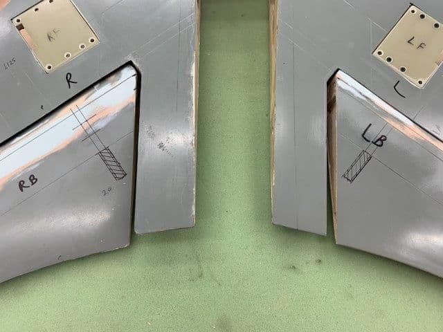
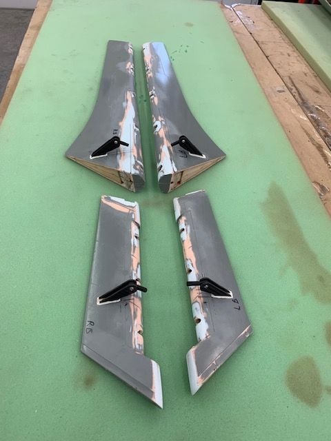
Started installing flap and aileron control horns. Flaps first.
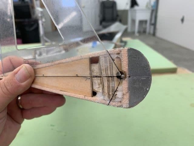
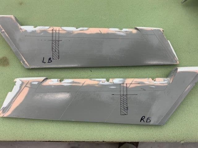
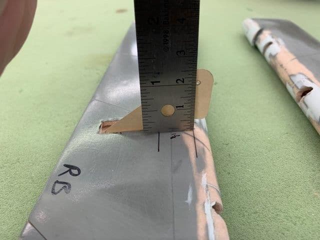
Flap deflection will be 30�. I read the full scale had 43� but I can't get that much with the gapless hinge set up on the model. I marked a 30� line from the hinge wire to plot the set back of the horn. I want the effective control horn line to be vertical below the hinge line when fully deflected for max leverage.
30� line projected from hinge wire to the top hole in the horn.
Flap horn set back position.
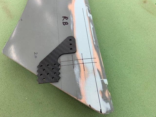
Flap horn setback has horn mounted about half way back on the flap
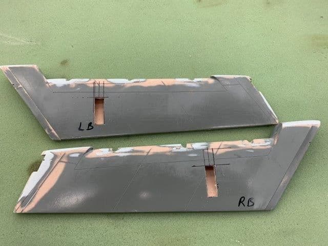
Flap horn holes plotted and cut out by xacto knife.
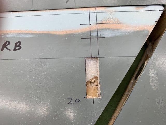
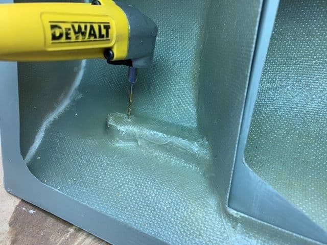
Both flaps had epoxy splooge and balsa at the horn mounting location that had to be ground out.
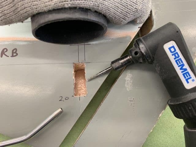
Carbide router bit used to remove wood and epoxy. Vacuum sucked out dust with assist from air gun.
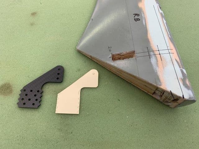
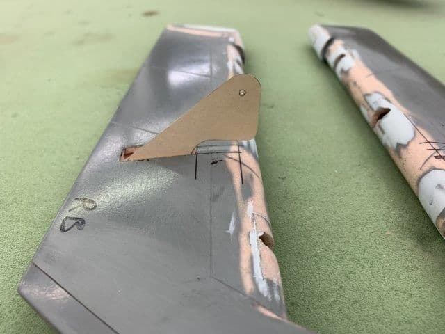
Card stock template made for horn fitting.
Started installing flap and aileron control horns. Flaps first.
Flap deflection will be 30�. I read the full scale had 43� but I can't get that much with the gapless hinge set up on the model. I marked a 30� line from the hinge wire to plot the set back of the horn. I want the effective control horn line to be vertical below the hinge line when fully deflected for max leverage.
30� line projected from hinge wire to the top hole in the horn.
Flap horn set back position.
Flap horn setback has horn mounted about half way back on the flap
Flap horn holes plotted and cut out by xacto knife.
Both flaps had epoxy splooge and balsa at the horn mounting location that had to be ground out.
Carbide router bit used to remove wood and epoxy. Vacuum sucked out dust with assist from air gun.
Card stock template made for horn fitting.
05-08-2019, 05:37 PM
#404
Thread Starter
My Feedback: (20)
Flap control horn dry fitting.
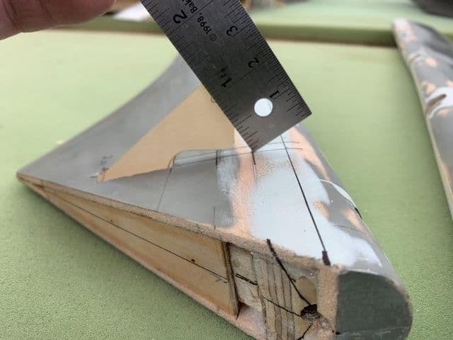
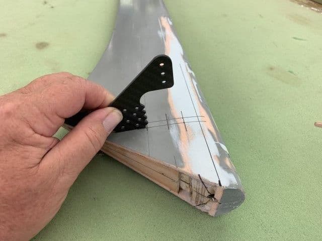
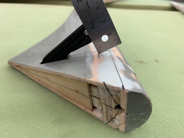
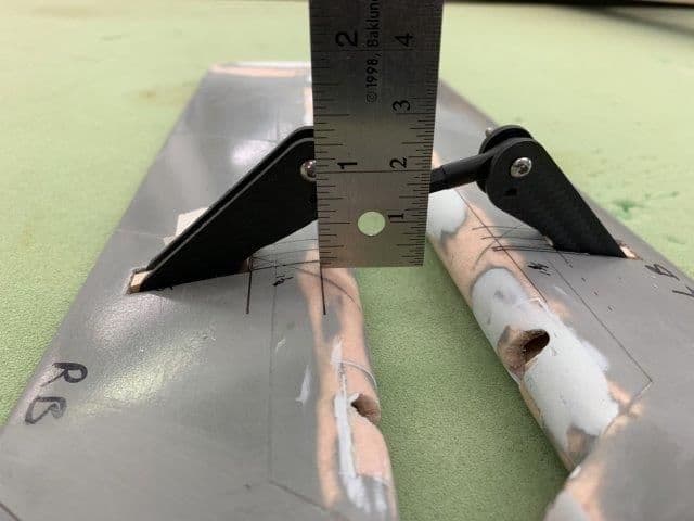
Paper template installed and position determined. The required torque calculations required by the AMA LTMA program were done using a 2" flap horn and a 1.25" servo horn. The effective 2" horn is 1" above the surface of the flap. The minimum torque required is 312 in/oz and the servo will deliver over 500 in/oz.
Top hole is 2" from the hinge line and 30� set back.
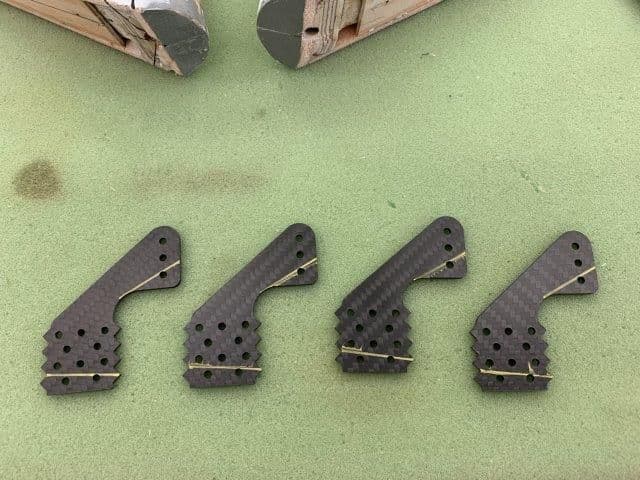
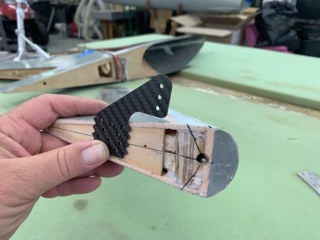
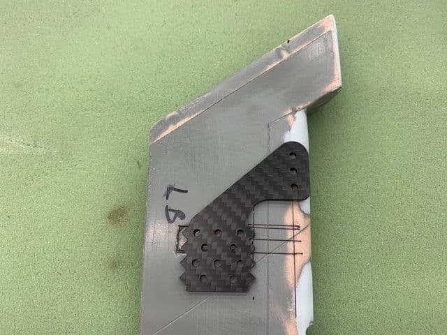
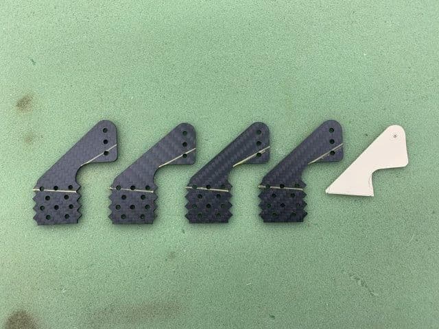
Carbon horns from Booma RC marked and ready to cut.
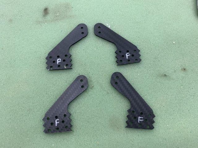
Flap horns marked with "F" after cutting with Dremel cut off wheel.
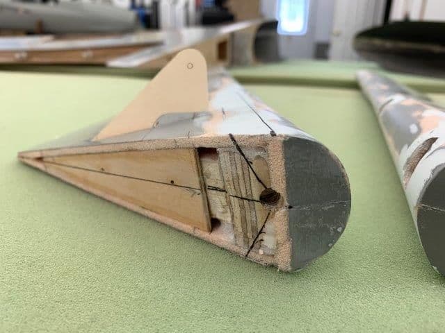
Carbon horn dry fit into flap and check for position accuracy.
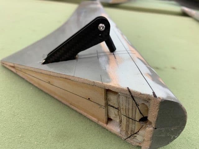
Horn done ready for hysol.
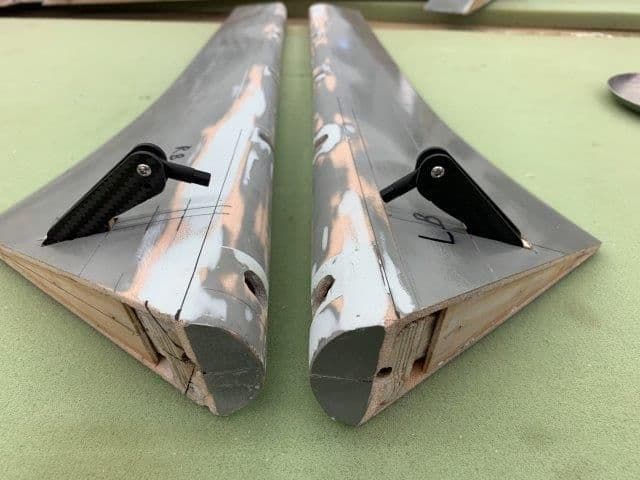
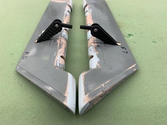
Both flap horns dry fit and ready for hysol.
Paper template installed and position determined. The required torque calculations required by the AMA LTMA program were done using a 2" flap horn and a 1.25" servo horn. The effective 2" horn is 1" above the surface of the flap. The minimum torque required is 312 in/oz and the servo will deliver over 500 in/oz.
Top hole is 2" from the hinge line and 30� set back.
Carbon horns from Booma RC marked and ready to cut.
Flap horns marked with "F" after cutting with Dremel cut off wheel.
Carbon horn dry fit into flap and check for position accuracy.
Horn done ready for hysol.
Both flap horns dry fit and ready for hysol.
Last edited by Viper1GJ; 05-08-2019 at 05:52 PM.
05-08-2019, 05:48 PM
#405
Thread Starter
My Feedback: (20)
Aileron control horns dry fitting.
Conrol horn holes are under hinge line on ailerons.
Location for aileron horns plotted
Holes for aileron horns cut out by Xacto knife
Paper template cut to fit ailerons.
The AMA LTMA torque calculations for the ailerons were made using 1.375" control horns and 1.25" servo arms. Minimum torque required is 121 in/oz and servo will deliver over 500 in/oz.
Carbon control horns marked and ready to cut.
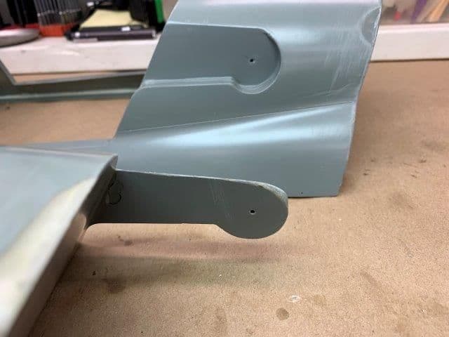
Aileron control horns dry fit and check for position.
Aileron control horns ready for hysol.
Conrol horn holes are under hinge line on ailerons.
Location for aileron horns plotted
Holes for aileron horns cut out by Xacto knife
Paper template cut to fit ailerons.
The AMA LTMA torque calculations for the ailerons were made using 1.375" control horns and 1.25" servo arms. Minimum torque required is 121 in/oz and servo will deliver over 500 in/oz.
Carbon control horns marked and ready to cut.
Aileron control horns dry fit and check for position.
Aileron control horns ready for hysol.
05-09-2019, 05:16 PM
#406
Thread Starter
My Feedback: (20)
Control horns glued in with hysol. Flight controls finished. Turbine and canopy hatches next.
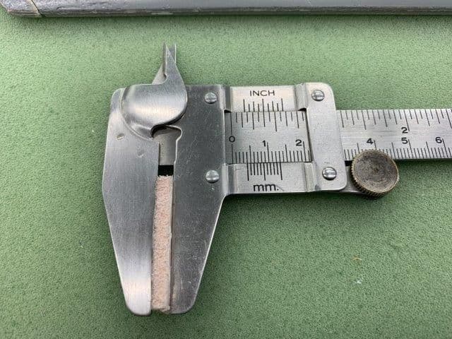
FYI for the question about the foam laminated core with the glass skins is about 4mm thick. Its very ridged and stiff and seems to make very strong parts.
05-10-2019, 05:11 PM
#408
Thread Starter
My Feedback: (20)
GeeBee, thanks for following the build. Its a slow process. A two seater would be cool but since I flew single seat so I'll keep the one holer. Besides I'm in over my head just mashing these parts together.
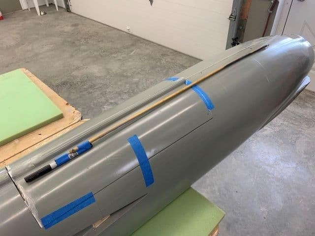
Made some headway on the hatches today.
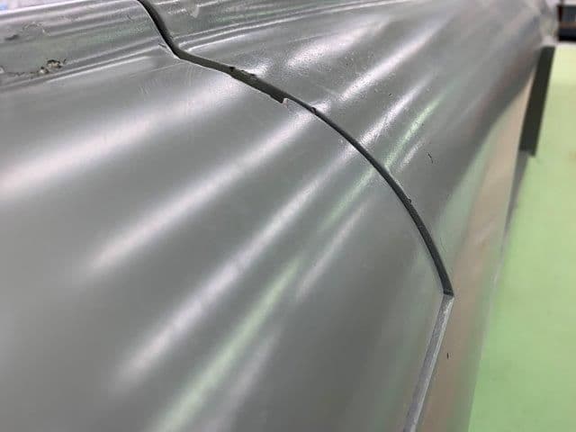
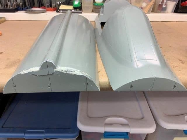
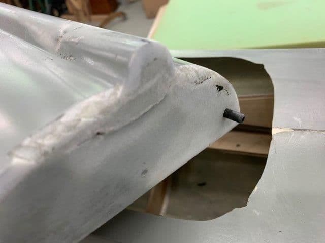
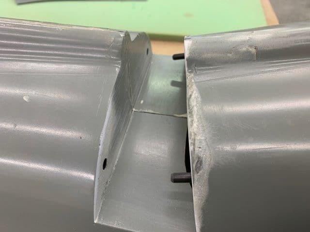
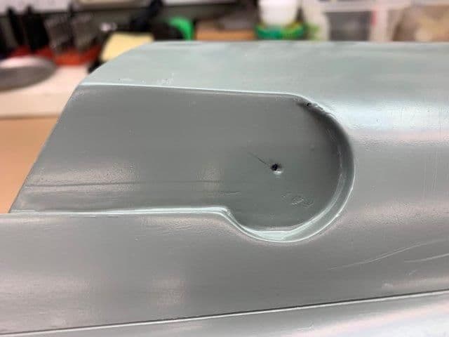
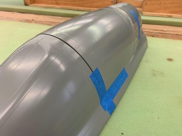
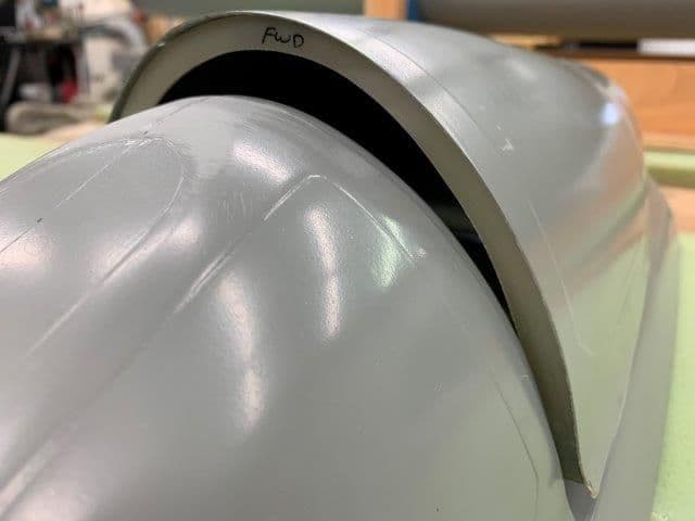
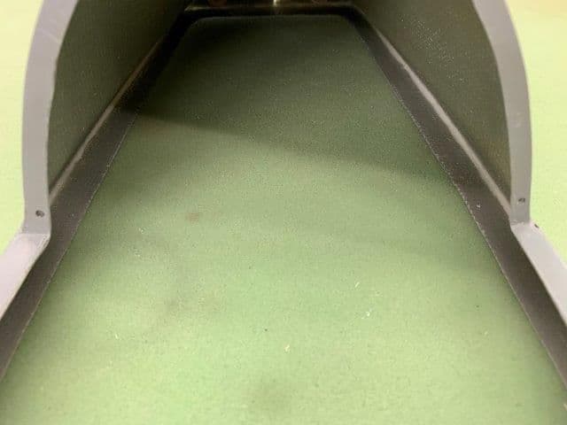
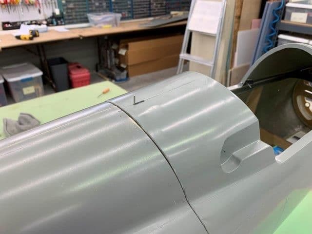
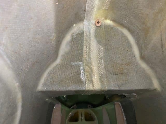
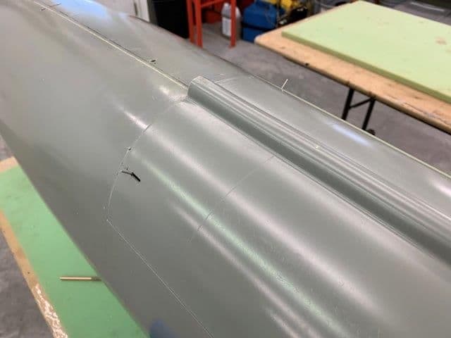
I started to fit the turbine hatch and found it was not square with the fuse. When in place the front and rear edges stuck out a lot. So I decided to mount it and then figure out how to make it fit. This is the aft right side, about 3-4 mm off.
Aft left side is recessed about 2 mm on bottom and a little on top
The front right edge is recessed about 3mm
The front left edge sticks out about 1/4 inch and looks like somebody took a hammer to it to smash it back in.
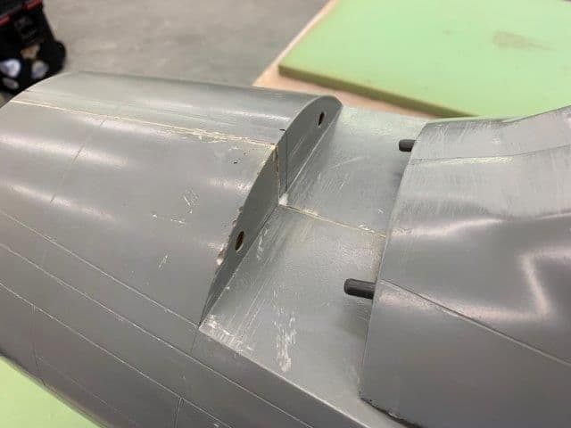
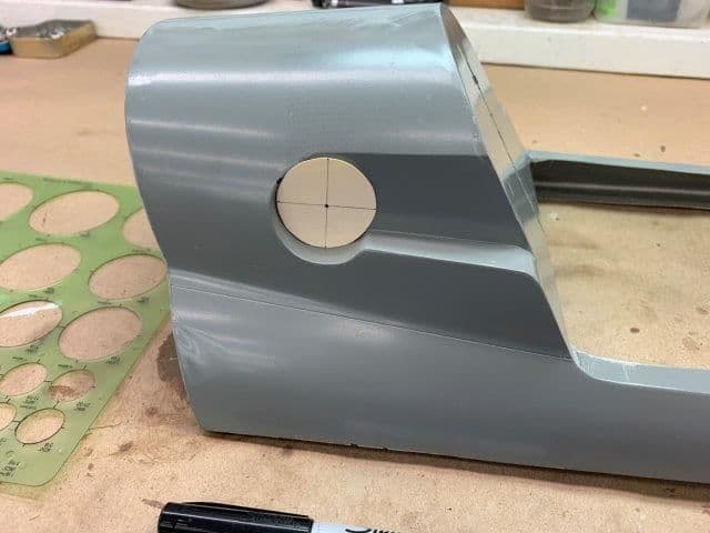
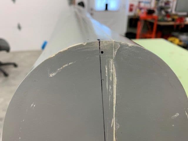
Dowel holes marked on front of the hatches
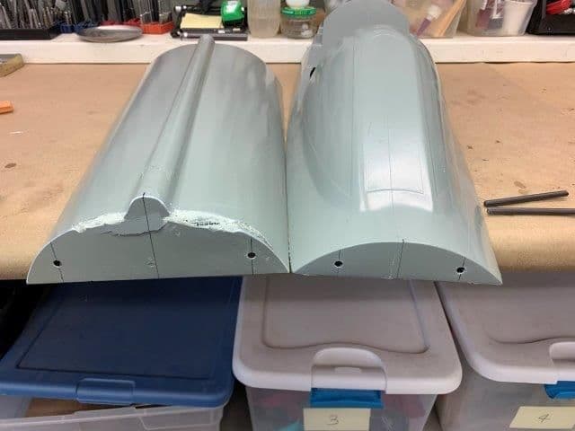
Dowel holes drilled for carbon tube dowels
Hatches taped to fuse and holes marked from inside. I made a long extension for the marker to get in from the rear to mark the turbine hatch holes.
Turbine hatch holes marked on front of hatch
Turbine hatch holes drilled.
Made some headway on the hatches today.
I started to fit the turbine hatch and found it was not square with the fuse. When in place the front and rear edges stuck out a lot. So I decided to mount it and then figure out how to make it fit. This is the aft right side, about 3-4 mm off.
Aft left side is recessed about 2 mm on bottom and a little on top
The front right edge is recessed about 3mm
The front left edge sticks out about 1/4 inch and looks like somebody took a hammer to it to smash it back in.
Dowel holes marked on front of the hatches
Dowel holes drilled for carbon tube dowels
Hatches taped to fuse and holes marked from inside. I made a long extension for the marker to get in from the rear to mark the turbine hatch holes.
Turbine hatch holes marked on front of hatch
Turbine hatch holes drilled.
Last edited by Viper1GJ; 05-11-2019 at 05:04 PM.
05-10-2019, 05:19 PM
#409
Thread Starter
My Feedback: (20)
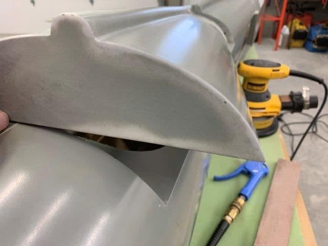
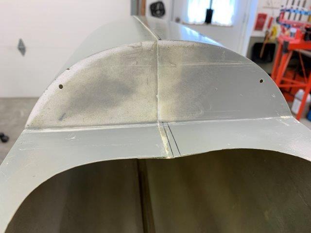
I started to sand the edges of the hatch and fuse to get a better fit. I used a permagrit bar and electric sander to make faster progress.
Sanding the front left side of the fuse opening
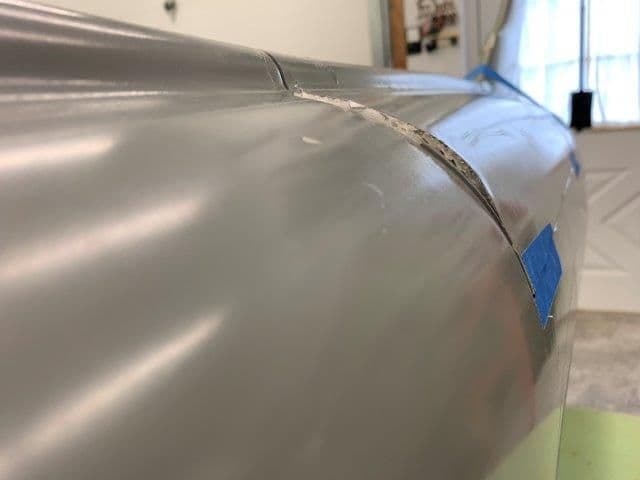
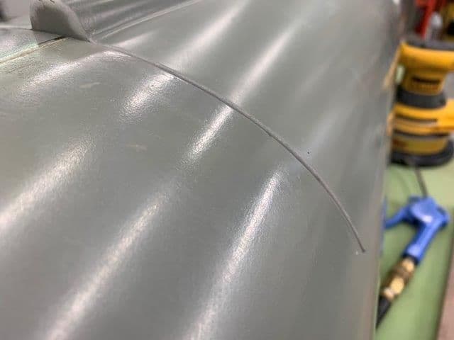
Sanded the front left edge of the hatch. Cut through the glass in one place. I will patch it from the inside with some glass and carbon tow in the corners.
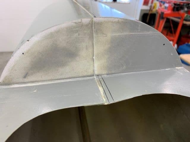
Sanded the aft right edge of the hatch
Sanded the aft right edge of the fuse opening.
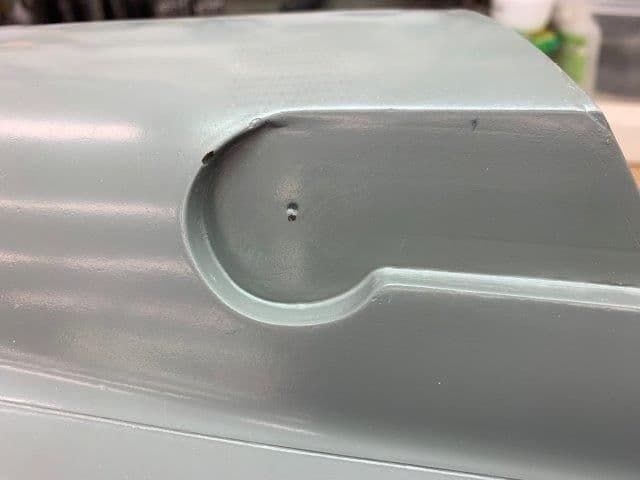
Fuse turbine hatch opening front edge sanded hard on left side.
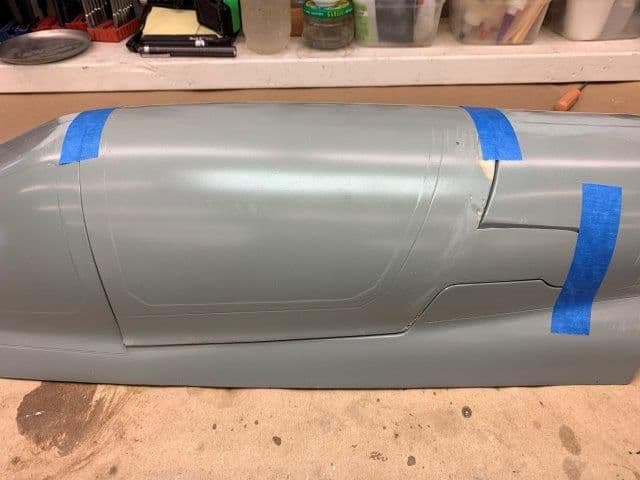
Final dry fitting with carbon dowels
After several hours of cut and fit I finally got the hatch to fit OK.
Sanding the front left side of the fuse opening
Sanded the front left edge of the hatch. Cut through the glass in one place. I will patch it from the inside with some glass and carbon tow in the corners.
Sanded the aft right edge of the hatch
Sanded the aft right edge of the fuse opening.
Fuse turbine hatch opening front edge sanded hard on left side.
Final dry fitting with carbon dowels
After several hours of cut and fit I finally got the hatch to fit OK.
05-10-2019, 05:28 PM
#410
Thread Starter
My Feedback: (20)
I am trying to not do any more body work than necessary to actually get the thing to fly in primer. I don't want to do all that work and time just to find out it will not fly right or the gear will not work. I will do body work, painting, and details after test flights if it is successful.
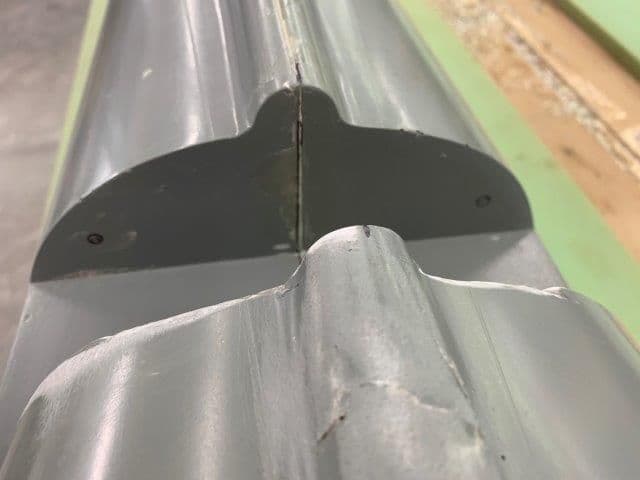
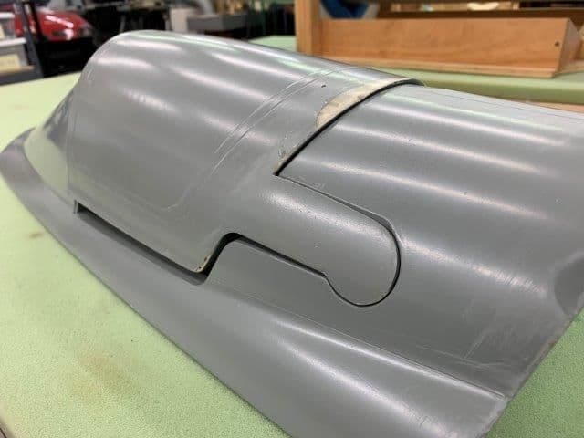
The cockpit hatch fit much better. I sanded all the edges smooth and it did not require much extra work to fit. It bows out some in the middle of the cockpit but its not bad enough to work on now.
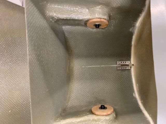
Canopy hatch dowels and holes
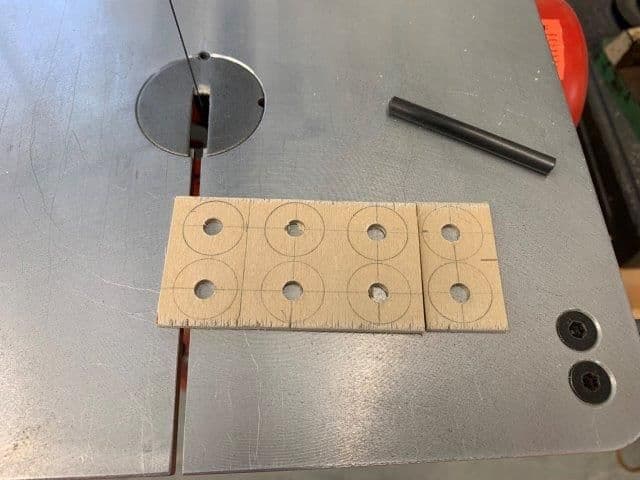
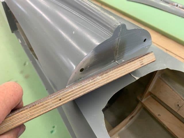
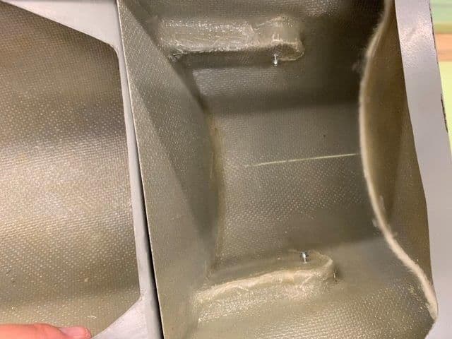
Plywood donuts cut to fit in front and back of all the carbon dowels
Ply donuts epoxied to inside of turbine hatch
Donuts on canopy hatch dowels. Waiting for hatch latches to show up next week to finish the hatch mounts.
The cockpit hatch fit much better. I sanded all the edges smooth and it did not require much extra work to fit. It bows out some in the middle of the cockpit but its not bad enough to work on now.
Canopy hatch dowels and holes
Plywood donuts cut to fit in front and back of all the carbon dowels
Ply donuts epoxied to inside of turbine hatch
Donuts on canopy hatch dowels. Waiting for hatch latches to show up next week to finish the hatch mounts.
05-11-2019, 04:33 PM
#411
Thread Starter
My Feedback: (20)
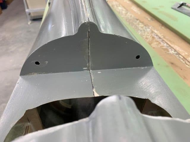
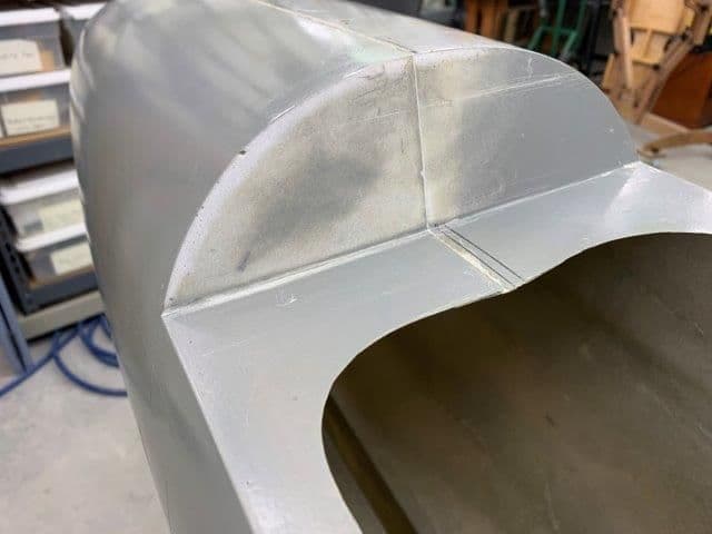
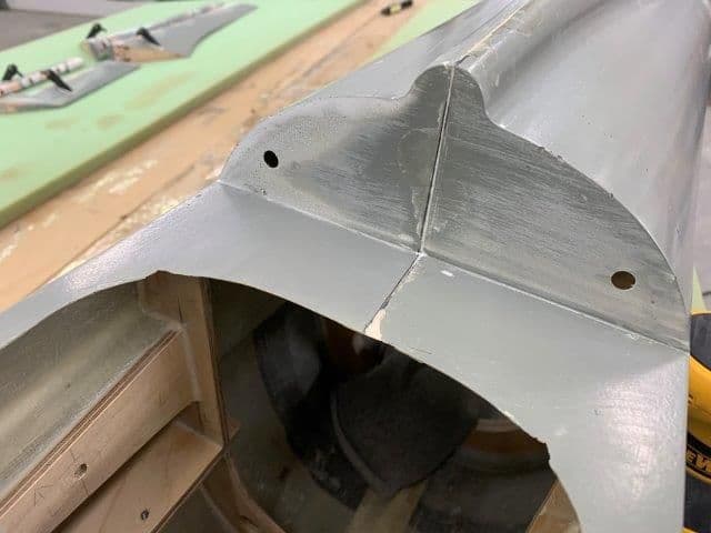
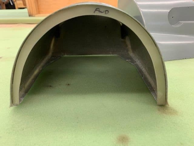
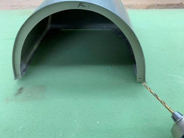
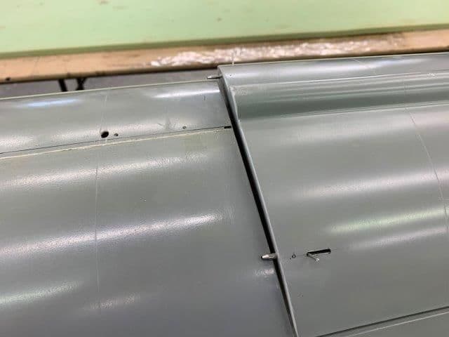
Hatches front dowels complete
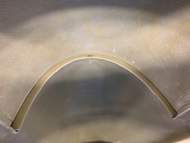
Front edge of turbine hatch glassed and stiffened with carbon fiber. Dowels glued in.
Turbine hatch dowel sockets glued in.
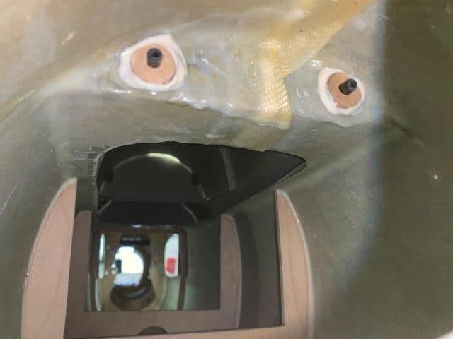
Canopy hatch front dowel sockets glued in.
Front of hatches done. Waiting on hatch latches to arrive to secure rear of hatches.
Front edge of turbine hatch glassed and stiffened with carbon fiber. Dowels glued in.
Turbine hatch dowel sockets glued in.
Canopy hatch front dowel sockets glued in.
Front of hatches done. Waiting on hatch latches to arrive to secure rear of hatches.
 05-11-2019, 04:49 PM
#413
Thread Starter
My Feedback: (20)
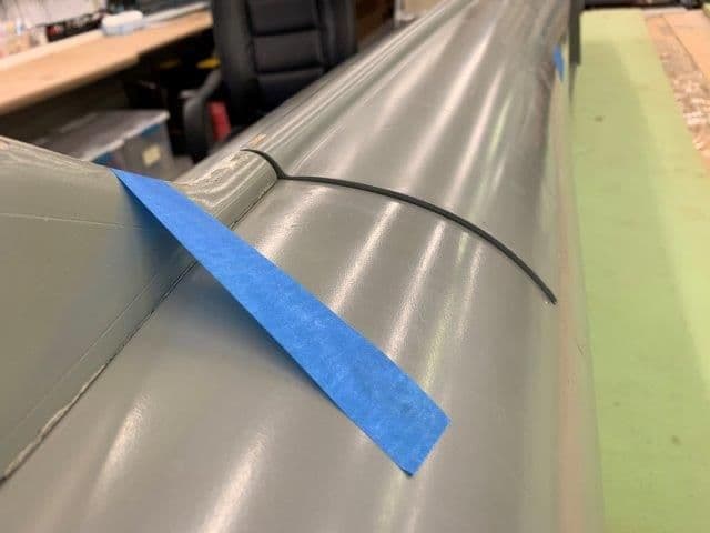
Next step is attaching the canopy to the canopy hatch. I do not plan to have a moveable canopy for test flights. I want to have it secured closed but be able to remove it and make it moveable in the future. Maybe after the test flghts I can make it open and close by servo or air but for now I just want to secure it closed.
Initial look showed it would not go up much without moving the hinges off center forward.
The problem is that the back of the canopy frame is solid and contacts the hatch when raised. To make it moveable the back of the canopy frame must be removed. That is a scale look anyway. However for now all I need to know is the center of the hinge for a bolt.
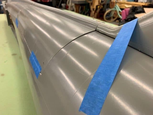
Finding the center of the hinge.
Left mark on center. Pilot hole drilled in center.
Right side mark above center. Pilot hole drilled on center.
Canopy taped in position for drilling inside out.
Hinges drilled through the pilot hole from inside out to mark the center on the canopy hinges.
Canopy hinges drilled on center.
Initial look showed it would not go up much without moving the hinges off center forward.
The problem is that the back of the canopy frame is solid and contacts the hatch when raised. To make it moveable the back of the canopy frame must be removed. That is a scale look anyway. However for now all I need to know is the center of the hinge for a bolt.
Finding the center of the hinge.
Left mark on center. Pilot hole drilled in center.
Right side mark above center. Pilot hole drilled on center.
Canopy taped in position for drilling inside out.
Hinges drilled through the pilot hole from inside out to mark the center on the canopy hinges.
Canopy hinges drilled on center.
05-11-2019, 05:00 PM
#414
Thread Starter
My Feedback: (20)
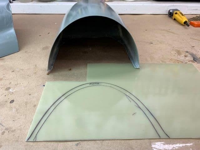
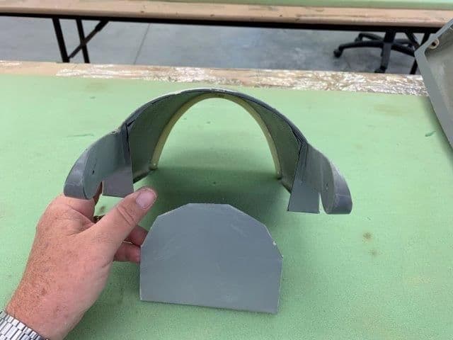
The plan is to secure the rear hinges with a bolt and secure the front of the canopy with two hatch latches on the lower front of the frame. To do this I needed to make a canopy frame bow on the front of the canopy frame. I will use the 1/16" G10 material I made the servo hatches from.
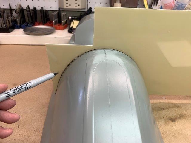
The G10 plate is held against the front of the canopy to trace the outside shape of the frame bow.
Outside edge traced.
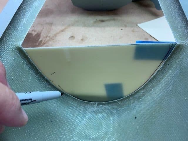
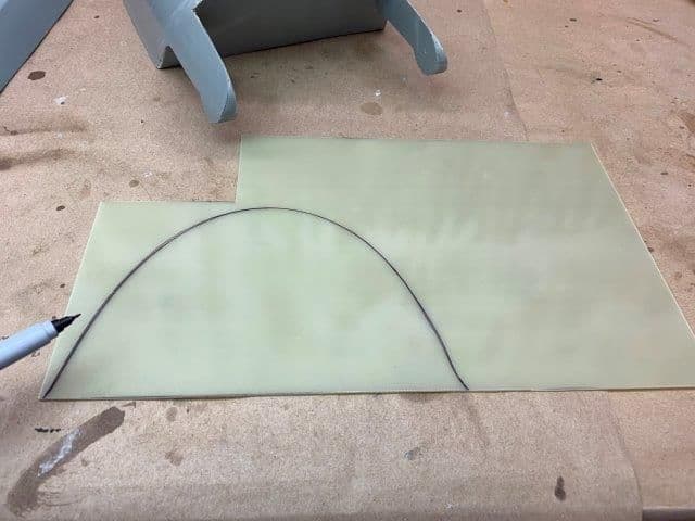
I taped the G10 to the front of the canopy frame and traced the inside shape.
Canopy bow frame traced ready to cut. The hatch latches will engage the canopy bow on each side at the bottom on the inside of the canopy. They will be hidden behind the lower forward part of the canopy wind screen frame. To be continued...
The G10 plate is held against the front of the canopy to trace the outside shape of the frame bow.
Outside edge traced.
I taped the G10 to the front of the canopy frame and traced the inside shape.
Canopy bow frame traced ready to cut. The hatch latches will engage the canopy bow on each side at the bottom on the inside of the canopy. They will be hidden behind the lower forward part of the canopy wind screen frame. To be continued...
 05-13-2019, 04:38 PM
#417
Thread Starter
My Feedback: (20)
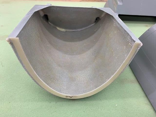
Canopy bow fabricated and glued in
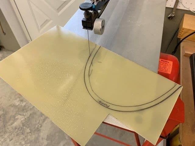
1/16" G10 left over from servo hatches used to make the canopy bow. Scroll saw cuts but I made 4 blade changes and went through two blades using top and bottom of both blades. The stuff is tough on blades.
First dry fit. Had to sand the bottom of both side to make it fit.
Canopy taped into position.
Hinges points tacked in with servo screws in previously drilled holes.
Canopy bow from inside looking forward ready for tack gluing with medium CA. The plan is to drill a hole on each side near the bottom of the bow and use a hatch latch mounted in front of the bow to lock the canopy down on each side
Canopy removed after bow tacked in with CA
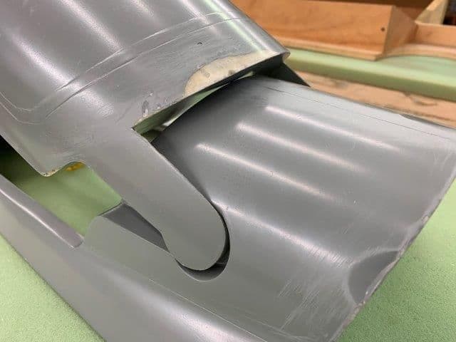
This is as far as it will open with out removing the rear section of the canopy
The rear wall of the canopy bumps into the top of the hatch behind the canopy and stops the opening. I will deal with that later.
1/16" G10 left over from servo hatches used to make the canopy bow. Scroll saw cuts but I made 4 blade changes and went through two blades using top and bottom of both blades. The stuff is tough on blades.
First dry fit. Had to sand the bottom of both side to make it fit.
Canopy taped into position.
Hinges points tacked in with servo screws in previously drilled holes.
Canopy bow from inside looking forward ready for tack gluing with medium CA. The plan is to drill a hole on each side near the bottom of the bow and use a hatch latch mounted in front of the bow to lock the canopy down on each side
Canopy removed after bow tacked in with CA
This is as far as it will open with out removing the rear section of the canopy
The rear wall of the canopy bumps into the top of the hatch behind the canopy and stops the opening. I will deal with that later.
05-15-2019, 04:51 PM
#418
Thread Starter
My Feedback: (20)
Securing canopy
Holes drilled in canopy bow
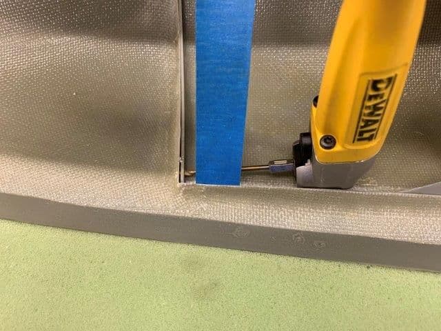
Canopy taped to canopy hatch and holes drilled through the bow into the forward canopy bow
Forward canopy bow holes drilled
Latch dry fit into holes
Latches tacked in place with medium CA. Everything worked so far. All parts will be secured with hysol later.
Holes drilled in canopy bow
Canopy taped to canopy hatch and holes drilled through the bow into the forward canopy bow
Forward canopy bow holes drilled
Latch dry fit into holes
Latches tacked in place with medium CA. Everything worked so far. All parts will be secured with hysol later.
Last edited by Viper1GJ; 05-15-2019 at 05:05 PM.
05-15-2019, 05:04 PM
#419
Thread Starter
My Feedback: (20)
Cockpit hatch latch installed
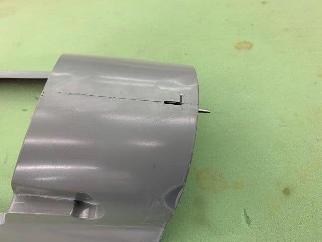
Latch slot cut and latch pin hole drilled
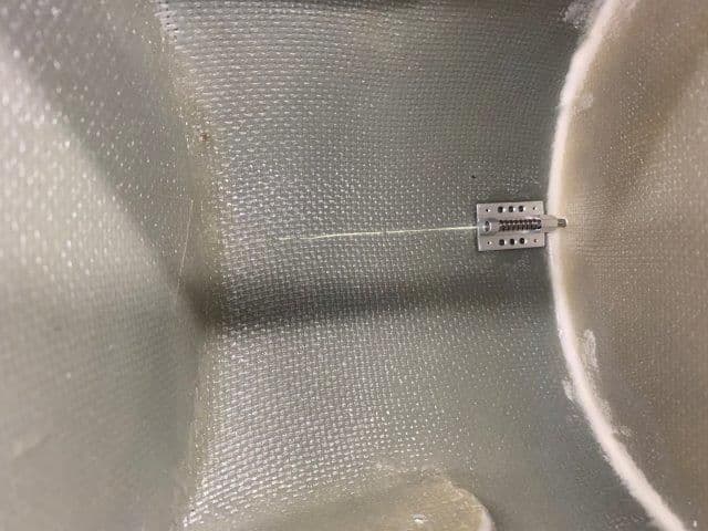
Latch tacked in place with medium CA
A dot of black craft paint applied to tip of latch pin
Latch pin hole position marked by fitting hatch and releasing latch pin
Cockpit latch fit and working
Plywood donut tacked in to backside to provide a better latch pin load bearing surface with 5 min epoxy. I will secure with all the parts with hysol later.
Latch slot cut and latch pin hole drilled
Latch tacked in place with medium CA
A dot of black craft paint applied to tip of latch pin
Latch pin hole position marked by fitting hatch and releasing latch pin
Cockpit latch fit and working
Plywood donut tacked in to backside to provide a better latch pin load bearing surface with 5 min epoxy. I will secure with all the parts with hysol later.
05-15-2019, 05:11 PM
#420
Thread Starter
My Feedback: (20)
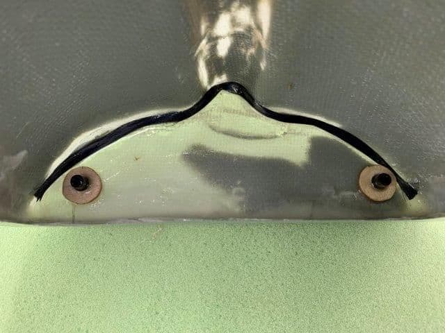
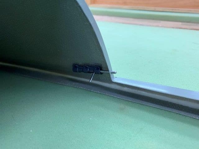
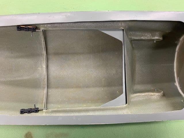
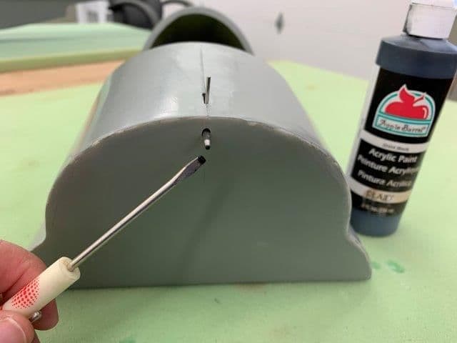
Turbine hatch latches installed
Turbine hatch latches installed as before with slot and latch pin hole cut and then tacked in with medium CA.
Latch pin holes marked with black paint as before.
Latch pin holes drilled.
Latches installed and working ok.
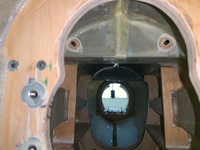
View from the rear
Plywood donuts installed as before and tacked in with 5 min epoxy. Will secure with hysol later.
Turbine hatch latches installed as before with slot and latch pin hole cut and then tacked in with medium CA.
Latch pin holes marked with black paint as before.
Latch pin holes drilled.
Latches installed and working ok.
View from the rear
Plywood donuts installed as before and tacked in with 5 min epoxy. Will secure with hysol later.
Last edited by Viper1GJ; 05-15-2019 at 05:33 PM.
05-15-2019, 05:29 PM
#421
Thread Starter
My Feedback: (20)
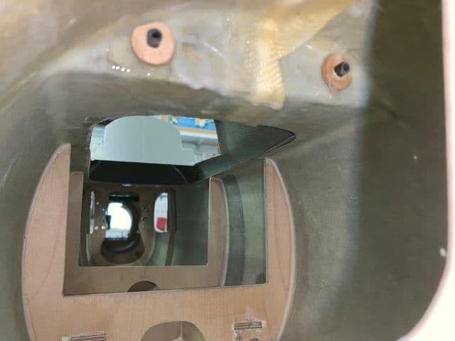
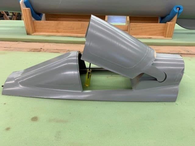
Canopy hinges completed
I cut the back wall out of the canopy frame with a dremel cutoff wheel and trimmed it with a permagrit grinding drum
Plywood support donuts installed and hinge arms drilled and tapped for a 6-32 x 1/2" socket head bolt. Fortunately the hinge arms had a wood block installed during layup to support the bolt. I hardened the threads with thin CA and the bolts are very well seated in the wood threads.
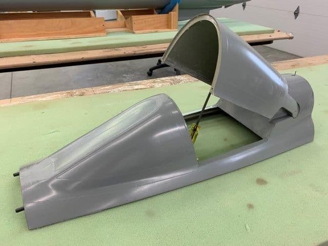
Now the canopy will raise and lower normally.
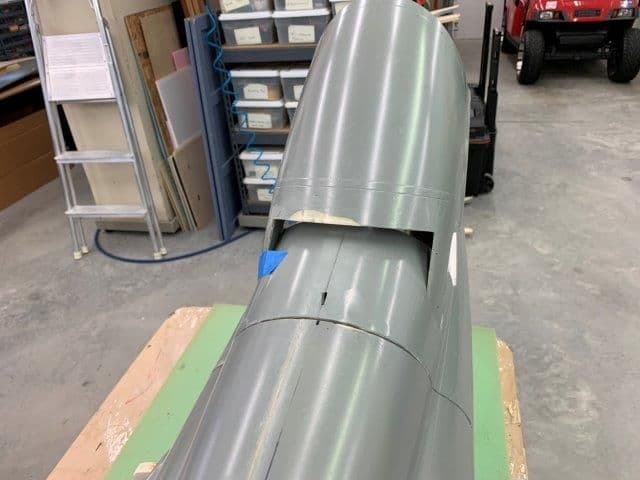
Rear view and hatch latch
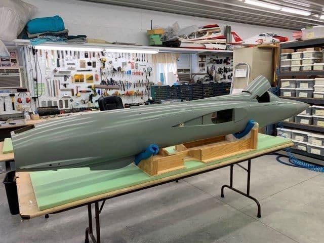
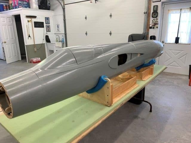
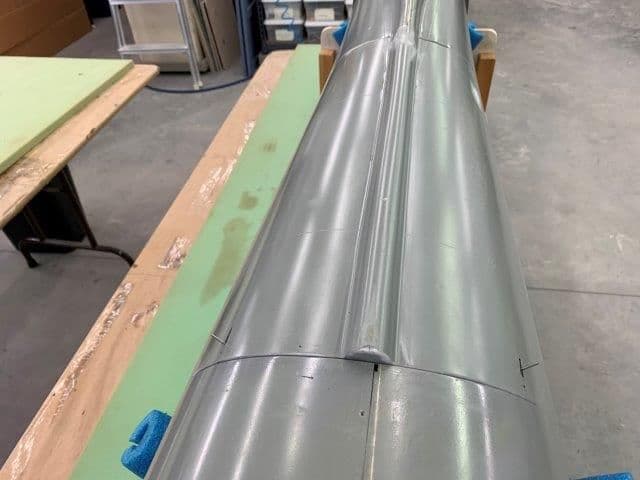
Happy snaps to look a the days progress.
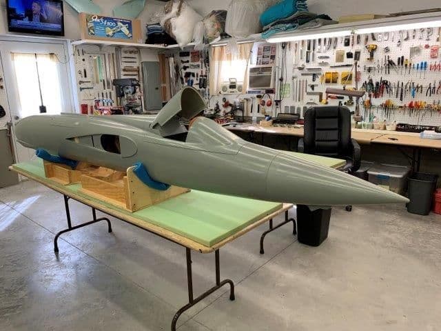
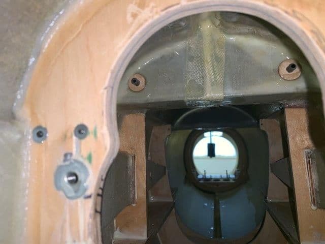
I installed the radome just for the "cool factor" in the photo
This will probably the last F-105 work till mid June. I'm going to Joe Nall this weekend, First In Flight jet rally the next week, and family vacation after that. Project to be continued...!
Fly safe and keep the greasy side down,
Gary
I cut the back wall out of the canopy frame with a dremel cutoff wheel and trimmed it with a permagrit grinding drum
Plywood support donuts installed and hinge arms drilled and tapped for a 6-32 x 1/2" socket head bolt. Fortunately the hinge arms had a wood block installed during layup to support the bolt. I hardened the threads with thin CA and the bolts are very well seated in the wood threads.
Now the canopy will raise and lower normally.
Rear view and hatch latch
Happy snaps to look a the days progress.
I installed the radome just for the "cool factor" in the photo
This will probably the last F-105 work till mid June. I'm going to Joe Nall this weekend, First In Flight jet rally the next week, and family vacation after that. Project to be continued...!
Fly safe and keep the greasy side down,
Gary
Last edited by Viper1GJ; 05-15-2019 at 05:43 PM.
05-20-2019, 04:43 PM
#422
Thread Starter
My Feedback: (20)
While packing for First In Flight jet rally today I began thinking about how to set up a drag chute system for the F-105.
My friend Frank Alvarez suggested the Details 4 Scale drag chute system. However they are not currently available. Today I thought of using the Jeti MRPM Hall sensor to determine wheel spin after landing and then activating the chute using logic switches for gear down, flaps down, throttle idle, brakes on, and wheels spinning.
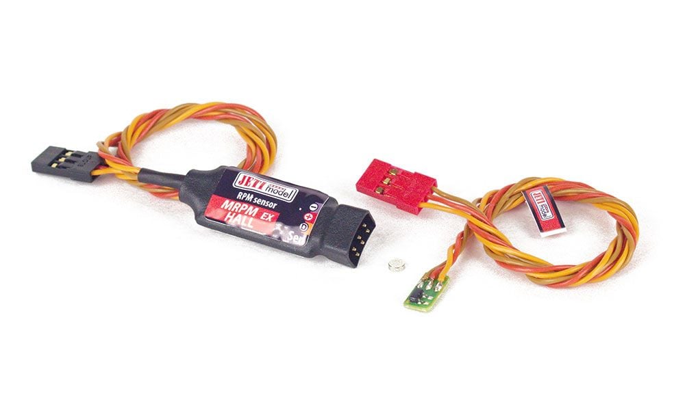
Has anybody done a drag chute system using the Jeti MRPM Hall sensor and logic switches yet?
Thanks,
Gary
My friend Frank Alvarez suggested the Details 4 Scale drag chute system. However they are not currently available. Today I thought of using the Jeti MRPM Hall sensor to determine wheel spin after landing and then activating the chute using logic switches for gear down, flaps down, throttle idle, brakes on, and wheels spinning.
Has anybody done a drag chute system using the Jeti MRPM Hall sensor and logic switches yet?
Thanks,
Gary
Last edited by Viper1GJ; 05-20-2019 at 04:49 PM.
05-20-2019, 06:21 PM
#423

Gary,
Not sure how you would use the hall effect sensor for wheel speed, as you would have to be counting pulses as the wheel rotates. I guess you could do some LUA programming, but not sure of any other way it would work.
I considered a micro-switch for a Weight-On-Wheels interlock for my Hunter drag chute after I had an inadvertent deployment on finals at about 10ft AGL that almost destroyed the model. In the end I opted to replace my standard Jeti 3-position switch I used for the chute (closed/ deploy/ release) with a 3-position locking switch I bought off of e-bay and soldered onto the little switch board. Now I have to lift the switch over the lock to deploy and release the chute.
It does look cool to deploy the chute at about 1-2ft in the flare.
The build looks good - keep going.
Paul

