


1/6 F-105 Build Thread
 01-29-2019, 06:43 PM
#301

Thread Starter
My Feedback: (20)
Flight control hinging is the next big issue to tackle.
The goal is to have removable wire hinged fight controls so that they can be removed for painting and repairs if necessary. Nobody ever has to repair a flight control do they...
Started working on rudder hinging and ran into two big issues.
First is the shape of the rudder and fin that inhibits easy assembly and disassembly. The hinges must be installed 90� to the hinge line. The last 5mm of movement to engage the hinge forks must be 90� to the hinge line, but this is impossible do to the trailing edge tab at the base of the fin and the counterbalance at the top of the rudder. This makes standard installation of hinges impossible.
Second issue was I tried to find hard points inside the rudder to mount hinges to but as I found out there were none. Surprise, Surprise...
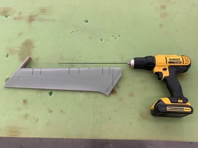
I started out drilling a small hole at the top and bottom of the rudder on center for the wire hinge. As the bit went through the ends there was nothing inside to drill through. Was same from top and bottom of rudder. The marks on the rudder were where my friend marked internal structure when he xrayed the surfaces. However, there was nothing there when I ran the but through the rudder.
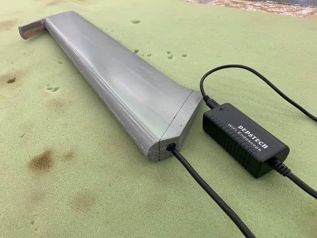
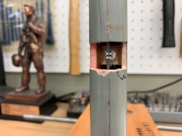
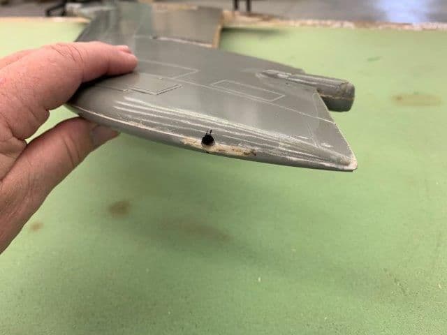
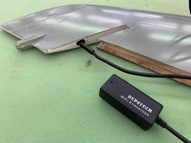
I needed to find out what was inside so I drilled a small hole in the bottom of the rudder with a step drill and inserted my endoscope camera.
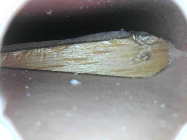
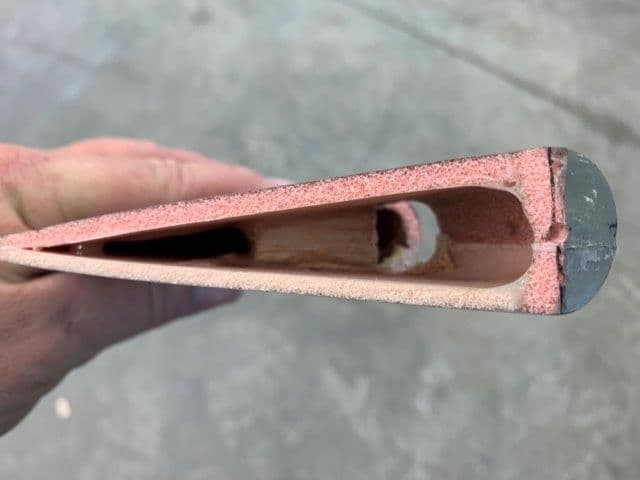
This is what I found. There was a small tear drop shaped block of balsa that was only glued to one side of the rudder. There were three of these apparently spaced for three pin type hinges, however they did not provide any wood at the center of the rudder for the hinge to attach to. I have no idea why they were only half as thick is the rudder but clearly they would not work. The marks on the balsa were made by the drill bit and the endoscope camera as I tried to force it past the balsa.
At this point I decided to cut the base of the rudder off to get a better look inside and also to provide some clearance to engage the hinge forks during assembly. I plan to make the base a removable cap that can be taken off to remove and replace the rudder. When rudder is attached the base cap will be reinstalled. I hope to be able to leave the counterbalance tab a the top of the rudder but we will see...
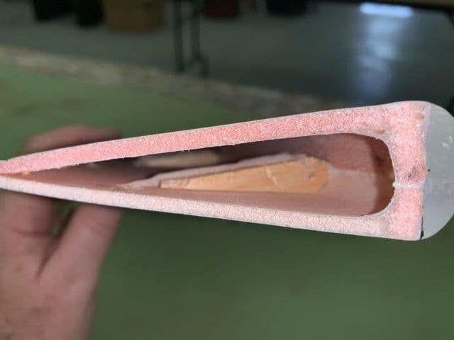
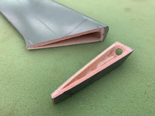
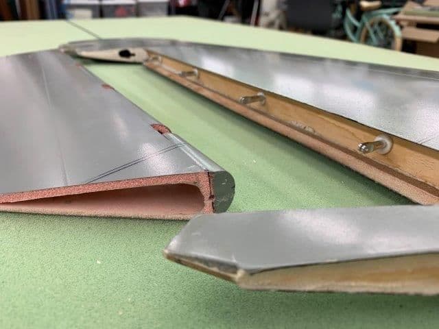
Here is the view inside the rudder. No wood leading edge and no wood in center for hinge points. Clearly this won't work and I will have to install some wood for mounting hinges.
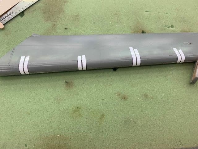
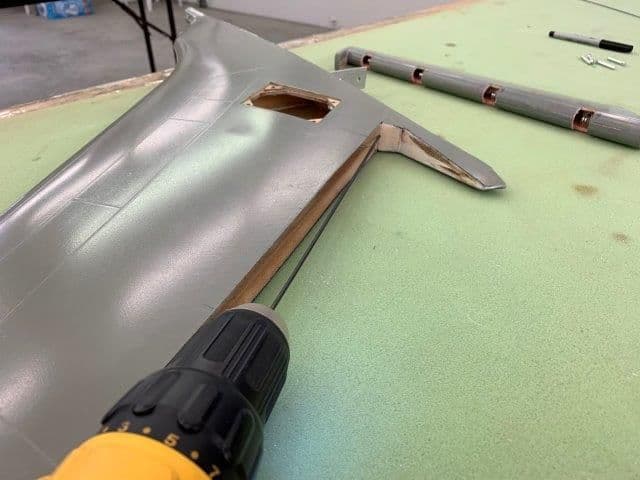
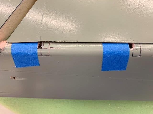
I considered splitting the rudder in half or just cutting off the rounded leading edge but finally decided on cutting out blocks to insert wood hinge mounts. This method left the rounded leading edge in place to aid in positioning the hinge pin stand off distance. I marked the position of each hinge and then laid 1/4" tape on both sides and make marks on the tape edges. This will allow 1/2" balsa wedges to be inserted for hinge mounts.
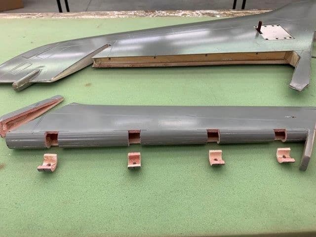
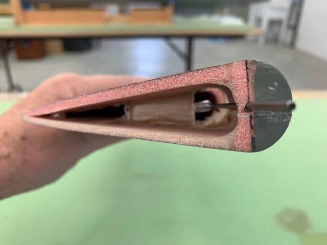
The marked plugs were cut out. As you can see there is no wood for mounting hinges. Sorta like a well known ARF supplier I've seen before. This photo also shows the tab at the base of the fin and the rudder counter weight slot. Both of these items prevent normal hinge install because the rudder can not slide into position with movement 90� to the hinge line. I'm hoping I can engage the hinge forks and leave the counter weight tab on by cutting off the base.
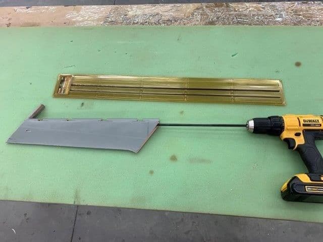
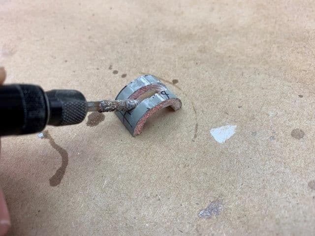
Next step was to remove the balsa that was in the way of the wire hinge wire. I used a new tool the first time that I got a couple of years ago when wondering around in a Tool King store. A 25" set of bits was perfect for grinding out the residual balsa blocks and make room for the new wire hinge. I knew I needed those bits, but not what for till today!
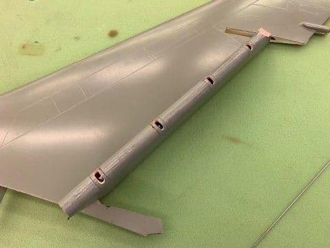
Wire inserted and hinges placed to determine the length of balsa wedges needed. It was at this point I realized that the rudder will have to have some kind of bushing and bearings on the top and bottom to keep it from rubbing on the base of the fin since it slides up and down on the wire. Always something else...
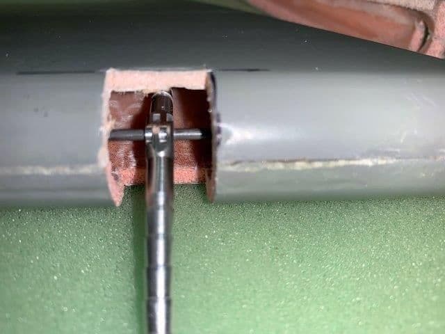
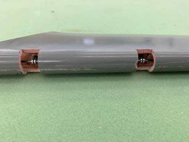
Close up of hinge pins showing hinge wire recessed into rudder about 1/2". More to come...
The goal is to have removable wire hinged fight controls so that they can be removed for painting and repairs if necessary. Nobody ever has to repair a flight control do they...
Started working on rudder hinging and ran into two big issues.
First is the shape of the rudder and fin that inhibits easy assembly and disassembly. The hinges must be installed 90� to the hinge line. The last 5mm of movement to engage the hinge forks must be 90� to the hinge line, but this is impossible do to the trailing edge tab at the base of the fin and the counterbalance at the top of the rudder. This makes standard installation of hinges impossible.
Second issue was I tried to find hard points inside the rudder to mount hinges to but as I found out there were none. Surprise, Surprise...
I started out drilling a small hole at the top and bottom of the rudder on center for the wire hinge. As the bit went through the ends there was nothing inside to drill through. Was same from top and bottom of rudder. The marks on the rudder were where my friend marked internal structure when he xrayed the surfaces. However, there was nothing there when I ran the but through the rudder.
I needed to find out what was inside so I drilled a small hole in the bottom of the rudder with a step drill and inserted my endoscope camera.
This is what I found. There was a small tear drop shaped block of balsa that was only glued to one side of the rudder. There were three of these apparently spaced for three pin type hinges, however they did not provide any wood at the center of the rudder for the hinge to attach to. I have no idea why they were only half as thick is the rudder but clearly they would not work. The marks on the balsa were made by the drill bit and the endoscope camera as I tried to force it past the balsa.
At this point I decided to cut the base of the rudder off to get a better look inside and also to provide some clearance to engage the hinge forks during assembly. I plan to make the base a removable cap that can be taken off to remove and replace the rudder. When rudder is attached the base cap will be reinstalled. I hope to be able to leave the counterbalance tab a the top of the rudder but we will see...
Here is the view inside the rudder. No wood leading edge and no wood in center for hinge points. Clearly this won't work and I will have to install some wood for mounting hinges.
I considered splitting the rudder in half or just cutting off the rounded leading edge but finally decided on cutting out blocks to insert wood hinge mounts. This method left the rounded leading edge in place to aid in positioning the hinge pin stand off distance. I marked the position of each hinge and then laid 1/4" tape on both sides and make marks on the tape edges. This will allow 1/2" balsa wedges to be inserted for hinge mounts.
The marked plugs were cut out. As you can see there is no wood for mounting hinges. Sorta like a well known ARF supplier I've seen before. This photo also shows the tab at the base of the fin and the rudder counter weight slot. Both of these items prevent normal hinge install because the rudder can not slide into position with movement 90� to the hinge line. I'm hoping I can engage the hinge forks and leave the counter weight tab on by cutting off the base.
Next step was to remove the balsa that was in the way of the wire hinge wire. I used a new tool the first time that I got a couple of years ago when wondering around in a Tool King store. A 25" set of bits was perfect for grinding out the residual balsa blocks and make room for the new wire hinge. I knew I needed those bits, but not what for till today!
Wire inserted and hinges placed to determine the length of balsa wedges needed. It was at this point I realized that the rudder will have to have some kind of bushing and bearings on the top and bottom to keep it from rubbing on the base of the fin since it slides up and down on the wire. Always something else...
Close up of hinge pins showing hinge wire recessed into rudder about 1/2". More to come...
Last edited by Viper1GJ; 01-29-2019 at 06:50 PM.

 01-30-2019, 04:33 PM
#303
Thread Starter
My Feedback: (20)
Jetjon,
Not surprised on hinge mounts, like so much on this build it has to be reworked.
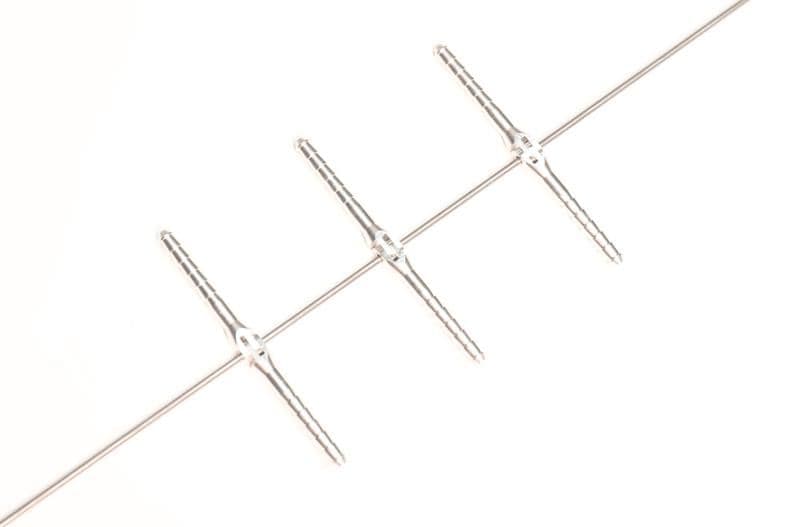
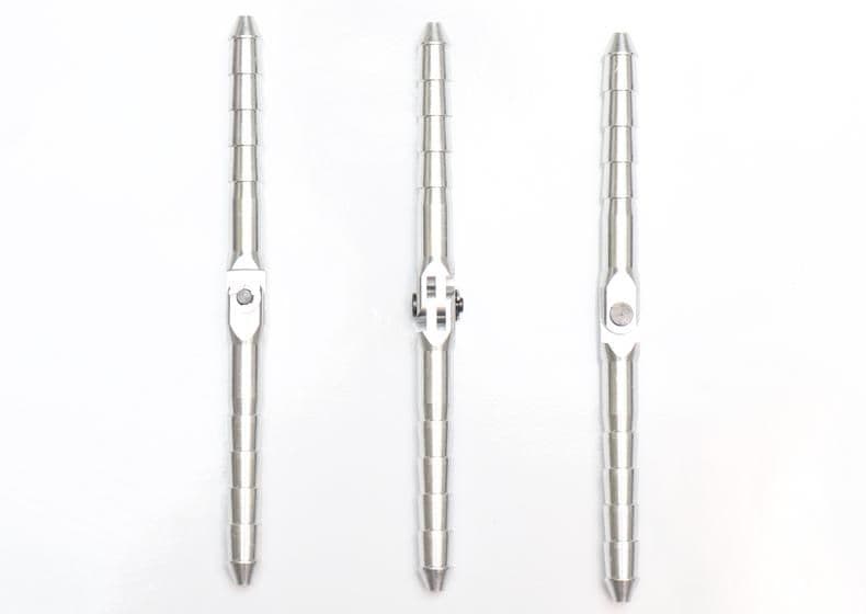
The aluminum pin hinges are really cool. I learned about them recently from Kerry Sterner. About a month ago my friend Frank Alvarez was over in the shop and we were pondering how to hinge the flight controls. He called Kerry for advice and that's where I learned about them.
They come in three sizes with E-clip pins or wire. You get them here:
https://www.aeroscale.shop/collections/hinges
Not surprised on hinge mounts, like so much on this build it has to be reworked.
The aluminum pin hinges are really cool. I learned about them recently from Kerry Sterner. About a month ago my friend Frank Alvarez was over in the shop and we were pondering how to hinge the flight controls. He called Kerry for advice and that's where I learned about them.
They come in three sizes with E-clip pins or wire. You get them here:
https://www.aeroscale.shop/collections/hinges
01-30-2019, 05:55 PM
#304
Thread Starter
My Feedback: (20)
Rudder hinging
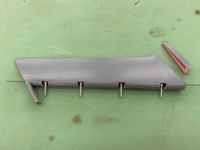
New balsa hinge mounts epoxied inside rudder
Hinges dry fit with wire inside rudder
Holes in hinge mounts had to be a little oversize to allow hinges to align all the hinges with the wire. Hysol will fill the gaps.
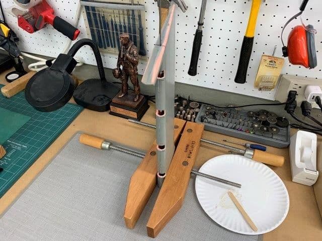
Rudder hinges hysoled in place. Rudder was clamped with wire vertical to prevent wire sag from causing misalignment during cure.
#3 hinge with hysol squeeze out around base making a good joint to hinge mount.
New balsa hinge mounts epoxied inside rudder
Hinges dry fit with wire inside rudder
Holes in hinge mounts had to be a little oversize to allow hinges to align all the hinges with the wire. Hysol will fill the gaps.
Rudder hinges hysoled in place. Rudder was clamped with wire vertical to prevent wire sag from causing misalignment during cure.
#3 hinge with hysol squeeze out around base making a good joint to hinge mount.
01-30-2019, 06:02 PM
#305
Thread Starter
My Feedback: (20)
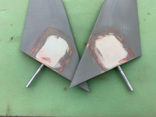
Stab skins sanded and glassed
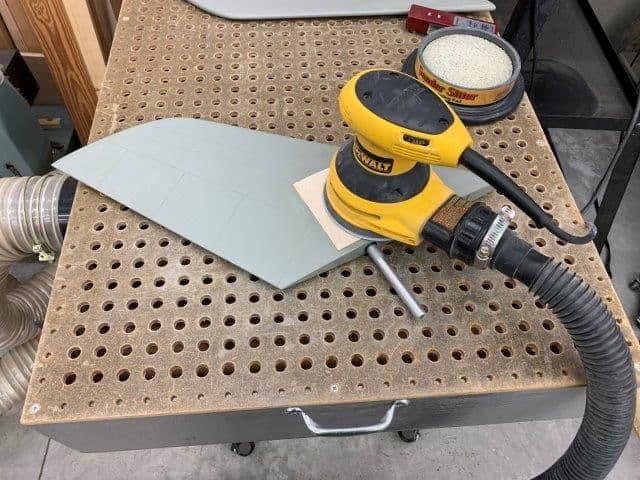
Balsa stab skins sanded to shape
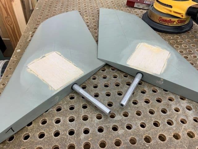
Final sanding complete
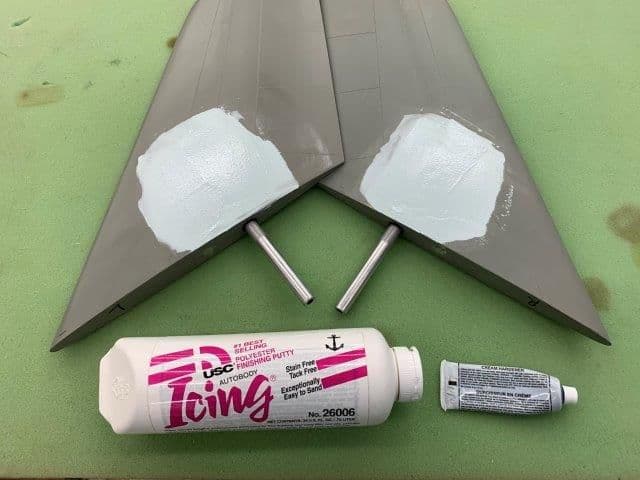
Icing light weight filler glazed over balsa patches
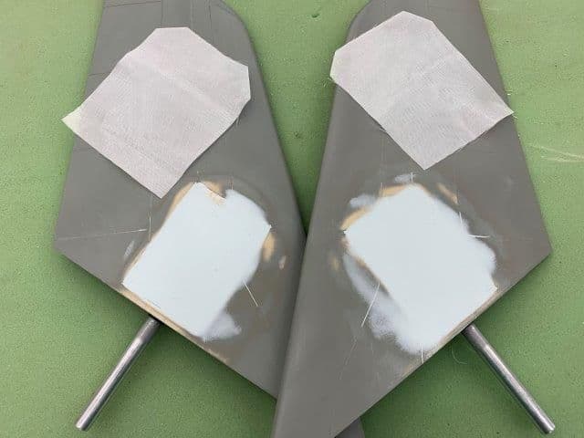
Filler sanded smooth and 2 oz glass cut ready for epoxy layup
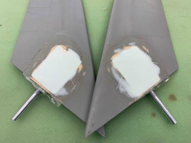
Epoxy glass layup completed
Balsa stab skins sanded to shape
Final sanding complete
Icing light weight filler glazed over balsa patches
Filler sanded smooth and 2 oz glass cut ready for epoxy layup
Epoxy glass layup completed
01-31-2019, 04:09 AM
#306

Gary,
Great progress. You make it look easy!
I love your dust collector sanding table - with I had one. I now have a heavy film of dust all over my garage from sanding the Buccaneer. Going to have to strip it all out and clean it once I'm done with the plug sanding.
I've seen those metal hinge pins and have been tempted to try them - what are your thoughts on them?
Paul
01-31-2019, 06:02 PM
#307
Thread Starter
My Feedback: (20)
Paul,
Thanks, as you know its never easy. The photos don't show all the hours of thinking, fitting, fussing, and tinkering to get it all done.
I have only two days work with the metal hinges but so far I love them. At first I was concerned with how hard it was to get the wire through all 4 but after I got them glued in it was a snap. Problem was they were flexing in the holes and binding the wire. Not any more. I think they will be great. I like the metal because of the long standoff outside the wood mounts needed for the rounded flight controls. I will use the 6 mm ones for the flaps since the flaps are so thick on the inboard sides.
01-31-2019, 06:21 PM
#308
Thread Starter
My Feedback: (20)
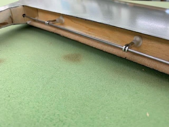
Paul, I built the downdraft table 20 years ago after my wife was complaining of dust migrating upstairs from my basement shop area. It's been one of the best tools I have, really keeps the dust mess under control.
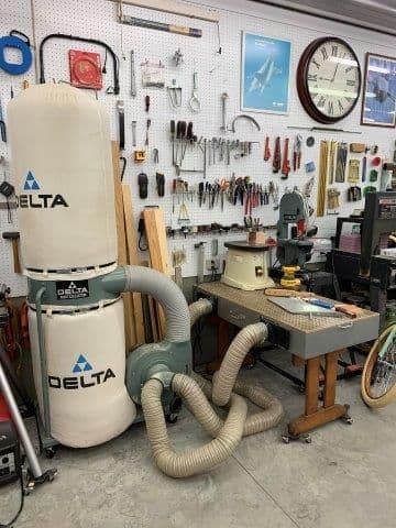
It uses a standard dust collector bag with two 4" hoses. The box sits on an old school desk from a thrift shop. The hoses can connect to my table saw and radial arm saw. Everything is on wheels for easy moving.
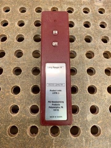
Remote control makes it easy to turn on and off.
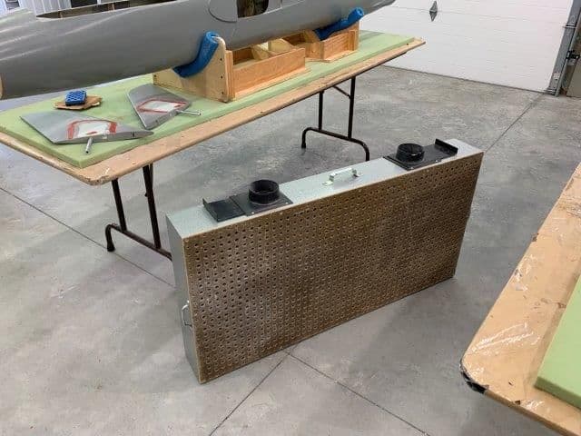
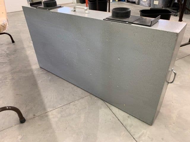
The is nothing to the box. 2" x 6" frame with 1/4" 2 x 4' pegboard on top. I opened all the holes to about 1/2" with a step drill. Standard 4" hose connectors on edge. Hardware store handles for easy carry.
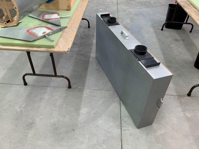
Bottom of box is 3/8 plywood. I had some left over silver Rustoleum hammer finish paint and painted the wood.
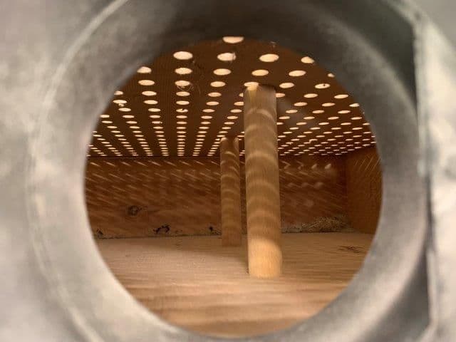
Inside every 12" is a dowel to keep the pegboard from sagging under sanding pressure.
Dowels are screwed in on the back side and just glued to bottom of the pegboard.
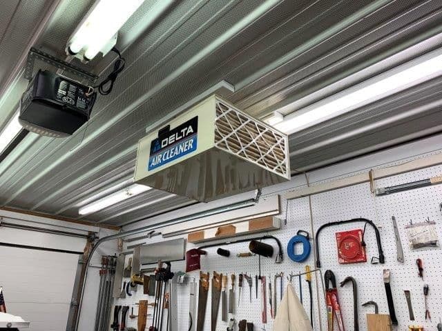
Augmented by ceiling dust collector also.
It uses a standard dust collector bag with two 4" hoses. The box sits on an old school desk from a thrift shop. The hoses can connect to my table saw and radial arm saw. Everything is on wheels for easy moving.
Remote control makes it easy to turn on and off.
The is nothing to the box. 2" x 6" frame with 1/4" 2 x 4' pegboard on top. I opened all the holes to about 1/2" with a step drill. Standard 4" hose connectors on edge. Hardware store handles for easy carry.
Bottom of box is 3/8 plywood. I had some left over silver Rustoleum hammer finish paint and painted the wood.
Inside every 12" is a dowel to keep the pegboard from sagging under sanding pressure.
Dowels are screwed in on the back side and just glued to bottom of the pegboard.
Augmented by ceiling dust collector also.
Last edited by Viper1GJ; 01-31-2019 at 06:23 PM.
01-31-2019, 06:36 PM
#309
Thread Starter
My Feedback: (20)
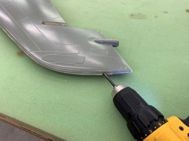
Hinging the rudder to the fin. Should be easy. Drill a few holes, mount the remaining hinge pins, and good to go... not so fast!
Drilled hinge wire hole in base of fin.
Drilled hole in upper fin
Marked and drilled hole in top of fin. Tried to get bit to exit lower hole but it would not do it. Felt like it was bouncing on something. Tried a larger bit. Bounced harder and kept rubbing on inside of fin skin. Was afraid it would punch out the side. What gives...?
Put light on bottom hole and looked inside and could see some "wood" in the center. No problem, drill through it. But the bit kept bouncing above or below it.
I finally drilled a big hole in the upper fin and used the endescope to see inside. As Gomer Pyle would say...Surprise, Surprise!
01-31-2019, 06:50 PM
#310
Thread Starter
My Feedback: (20)
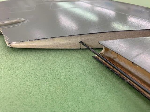
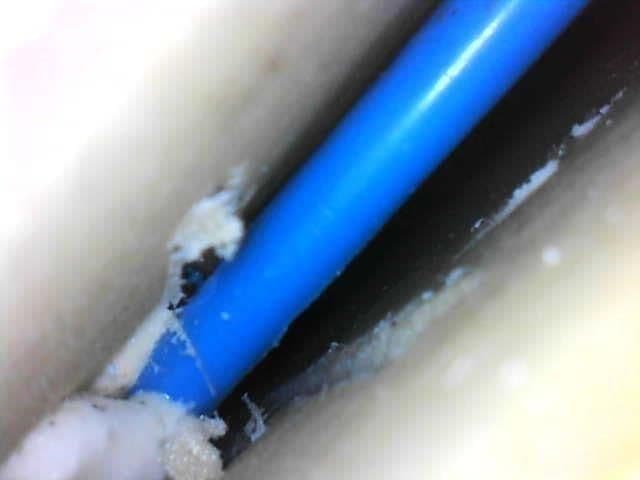
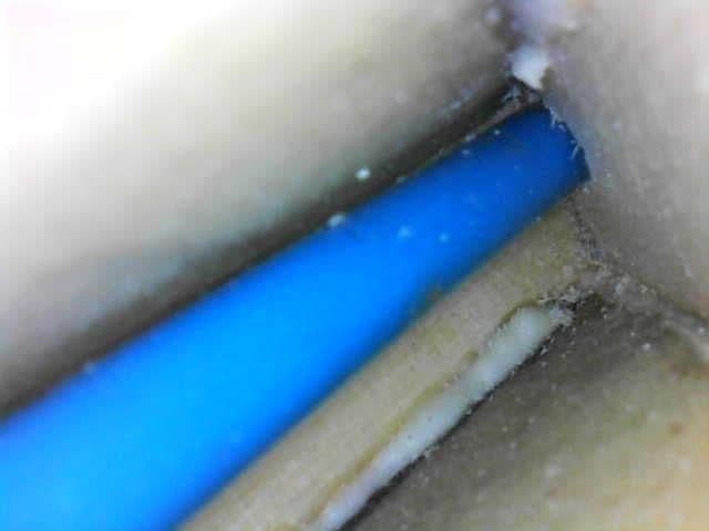
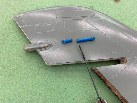
Blue tube embedded inside fin. I found a tube apparently for running light wires to the fin tail light inside. This is why the bit kept bouncing around.
Trailing edge of fin is to lower left in photo You can see my bit marks below and above in the Airex material

This area in way of hinge wire through the center area
Tube run through the spar toward the leading edge
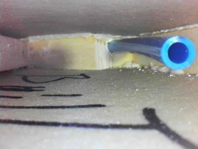
I could not find any exit hole for the tube. I finally stuck the endescope up in the servo well and found this about 6" up out of sight and out of reach. I also found the build date 2/20/2013 written on the inside of the fin. So now we know when the fin was made.
Trailing edge of fin is to lower left in photo You can see my bit marks below and above in the Airex material
This area in way of hinge wire through the center area
Tube run through the spar toward the leading edge
I could not find any exit hole for the tube. I finally stuck the endescope up in the servo well and found this about 6" up out of sight and out of reach. I also found the build date 2/20/2013 written on the inside of the fin. So now we know when the fin was made.
Last edited by Viper1GJ; 01-31-2019 at 07:21 PM.
01-31-2019, 07:03 PM
#311
Thread Starter
My Feedback: (20)
I elected to remove the tube in the area of the hinge wire. I will not be putting lights in and if I did I would use a different system to get the wires in. I could not get any tools inside to cut the tube so I cut it by melting it with a hot wire.
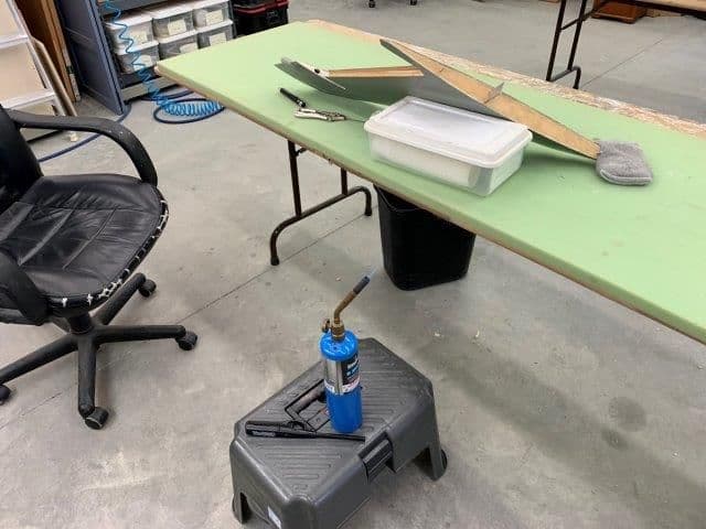
Melting setup with torch running ready to go.
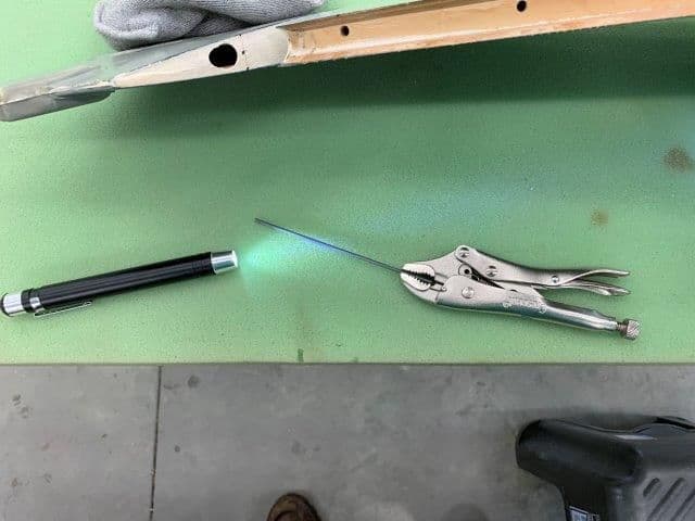
Hot wire held in vise grips and flashlight to see.
The operating area.
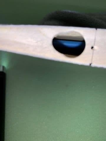
Took two cuts. As hot wire touched the tube it filled the cavity with smoke and made it impossible to see. Took several passes and finally got it out.
Melting setup with torch running ready to go.
Hot wire held in vise grips and flashlight to see.
The operating area.
Took two cuts. As hot wire touched the tube it filled the cavity with smoke and made it impossible to see. Took several passes and finally got it out.
01-31-2019, 07:19 PM
#312
Thread Starter
My Feedback: (20)
Hinging rudder to fin.

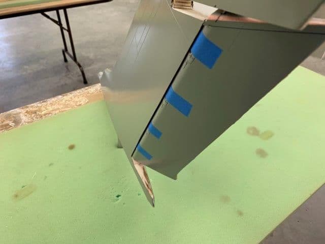
It quickly became apparent that there was no way to insert the hinges in the fin with the balance tab attached to the rudder. No angle, no side, and no force would work. So I had to cut if off. After that no problem. I will figure a way to re attach it and the base of the rudder also after hinges are in.
Hinge pins in fin with hysol and ready to engage the hinges in the rudder. Before this photo there were multiple dry runs and test fits to make sure everything would fit, move, and keep the wire straight. I had to enlarge the top and bottom holes in the fin to get it right. I can fix that later.
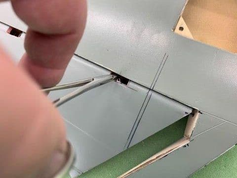
Each hinge had to be engaged with a pair of small forceps one at a time and then the wire pushed through.
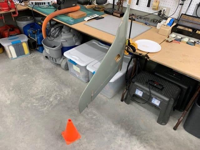
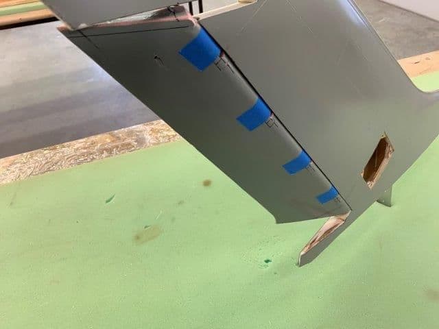
Fin hung rudder down for hysol cure to make sure the hinge stand off in the fin would keep enough clearance on the rudder for good movement. Orange cone set to keep the shop dummy from walking into it and breaking it off.
It quickly became apparent that there was no way to insert the hinges in the fin with the balance tab attached to the rudder. No angle, no side, and no force would work. So I had to cut if off. After that no problem. I will figure a way to re attach it and the base of the rudder also after hinges are in.
Hinge pins in fin with hysol and ready to engage the hinges in the rudder. Before this photo there were multiple dry runs and test fits to make sure everything would fit, move, and keep the wire straight. I had to enlarge the top and bottom holes in the fin to get it right. I can fix that later.
Each hinge had to be engaged with a pair of small forceps one at a time and then the wire pushed through.
Fin hung rudder down for hysol cure to make sure the hinge stand off in the fin would keep enough clearance on the rudder for good movement. Orange cone set to keep the shop dummy from walking into it and breaking it off.
02-01-2019, 07:00 AM
#313
Thx for the info on those cool hinges!...I have to ask......any idea WHY a plastic blue tube is glued inside the fin?? It seems like mysterious stuff just keeps popping up w/ your build! It's a blast keeping up w/ your adventure on this build!
02-01-2019, 07:01 AM
#314

He mentioned it in his post, it was most likely placed there to aid in feeding a wire for the installation of a light system. If you think about it, it's pretty funny/sad how someone would have the forethought to do something like that but then not install hinge blocks.
02-01-2019, 07:16 AM
#316
He mentioned it in his post, it was most likely placed there to aid in feeding a wire for the installation of a light system. If you think about it, it's pretty funny/sad how someone would have the forethought to do something like that but then not install hinge blocks.
02-01-2019, 04:45 PM
#317
Thread Starter
My Feedback: (20)
Jetjon, Unfortunately I don't know much about the origin of the F-105 other than the Youtube videos. I was told that some guys in Texas I think, did a lot of work on the design prior to the build but I don't really know for sure.
02-01-2019, 05:41 PM
#318
Thread Starter
My Feedback: (20)
Spot prime and sanded stab patches
Glazing putty applied and sanded around edges of glass fabric
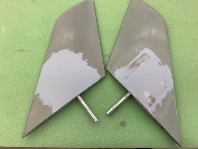
2K primer brushed on patch area and wet sanded. I did not want to set up sprayer for such a small task.
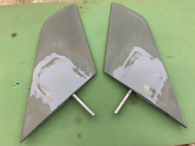
All wet sanding done down to 400 grit paper. Stabs ready for prime and paint... after test flying!
Glazing putty applied and sanded around edges of glass fabric
2K primer brushed on patch area and wet sanded. I did not want to set up sprayer for such a small task.
All wet sanding done down to 400 grit paper. Stabs ready for prime and paint... after test flying!
02-01-2019, 05:53 PM
#319
Thread Starter
My Feedback: (20)
Rudder hinge slots
Hinges in fin trailing edge after hysol cured. There is significant stand off from wood because of the thickness of the flight control so this is where the metal hinges really help. There is no bending or flexing of the hinge pins after epoxy cure. I really like the metal hinges now. The stand off will be greater on the flaps so I am using a longer 6mm hinge there.
Cutting clearance slots in rudder hinge cover blocks
Dry fit test of rudder throw to right.
To left
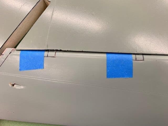
Hinge slots not visible when rudder is centered. Some where my rudder got a hole punched into it. More body work.
Slots only visible when rudder is deflected
Finished hinge slots
Hinges in fin trailing edge after hysol cured. There is significant stand off from wood because of the thickness of the flight control so this is where the metal hinges really help. There is no bending or flexing of the hinge pins after epoxy cure. I really like the metal hinges now. The stand off will be greater on the flaps so I am using a longer 6mm hinge there.
Cutting clearance slots in rudder hinge cover blocks
Dry fit test of rudder throw to right.
To left
Hinge slots not visible when rudder is centered. Some where my rudder got a hole punched into it. More body work.
Slots only visible when rudder is deflected
Finished hinge slots
Last edited by Viper1GJ; 02-02-2019 at 05:51 PM.
02-01-2019, 06:16 PM
#320
Thread Starter
My Feedback: (20)
Replacing base of rudder
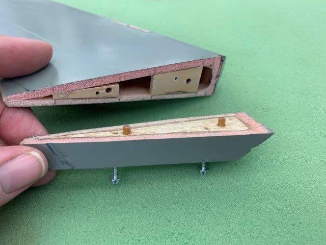
Since the base of the rudder must be removed to engage the hinge forks when installing the rudder it has to have a method to hold it on. I fabricated some wood dowels to align bottom of rudder and two servo screws to hold it on.
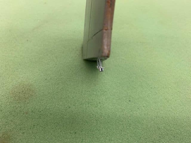
Screws are tilted to right to allow the ball driver tool to better engage from an angle on the right side of the fuse.
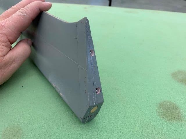
Screw heads countersunk to clear the base of the fin and inspection hole plugged with balsa.
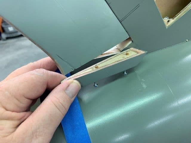
Test fit with fin on fuse. I taped the fin to the fuse and tested fit to ensure the rudder base could be properly installed.
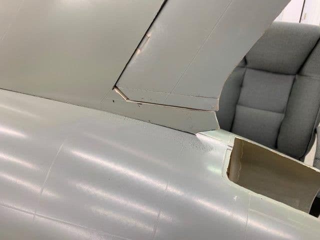
Its tight but it will fit in place. Something along the way here put the big wrinkle in the trailing edge of the rudder and the dent will have to be filled.
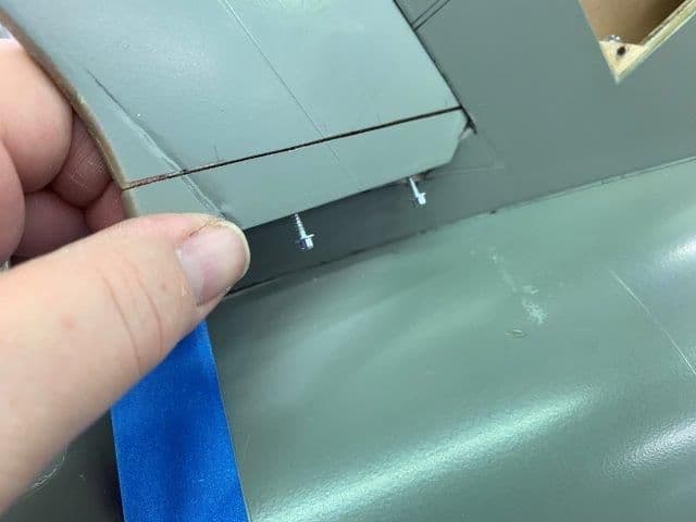
Ball driver will clear fuse to engage the screws.
Base of rudder in place. WIll have to do some sanding to align the trailing edges.
Since the base of the rudder must be removed to engage the hinge forks when installing the rudder it has to have a method to hold it on. I fabricated some wood dowels to align bottom of rudder and two servo screws to hold it on.
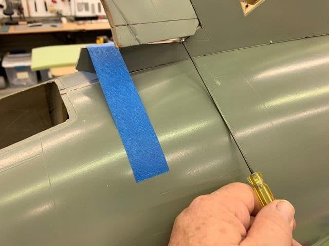
Screws are tilted to right to allow the ball driver tool to better engage from an angle on the right side of the fuse.
Screw heads countersunk to clear the base of the fin and inspection hole plugged with balsa.
Test fit with fin on fuse. I taped the fin to the fuse and tested fit to ensure the rudder base could be properly installed.
Its tight but it will fit in place. Something along the way here put the big wrinkle in the trailing edge of the rudder and the dent will have to be filled.
Ball driver will clear fuse to engage the screws.
Base of rudder in place. WIll have to do some sanding to align the trailing edges.

 02-02-2019, 12:36 PM
#322
This model could have been one of the finest out there..........just didn't work out that way for the buyers of the kit.
02-02-2019, 12:51 PM
#324

I don�t know any of the details or history which there is apparently a lot of, but this is my current favorite thread. The re-engineering although I�m sure a PIYA is really fun to follow. The speed and daily progress is amazing on your part. I look forward to your updates every day. Nice job!
02-02-2019, 04:40 PM
#325
My Feedback: (26)
While I'm sorry for all your issues, I really like this thread. It reminds me of when the forums used to be filled with guys BUILDING airplanes. With the current proliferation of ARFs it's rare to see a thread where someone is demonstrating true skill and craftsmanship and is actually creating something unique.