


1/6 F-105 Build Thread
 01-18-2019, 06:11 PM
#276

Thread Starter
My Feedback: (20)
David,
Thanks for the recommendations. I was planning on 2 pins attached to the inside of each rib and blocked in with wood. You can see the blocks on the outside of the ribs just forward of the pivot rod for the existing pins which were imbedded in the rib. I have ground off the blocks that were on the inside of the ribs where I was going to attach the new pins. I was going to hysol everything in place before closing up the stabs.
My pivot tubes are 2024 aluminum 1/2" OD with .120 walls. The walls are almost 1/8" thick. I had not thought of having a solid center core for the pins. I was planning on fastening the pins with into the rods with hysol by sliding them in and out working the hysol inside the holes. That is why I cut such a wide opening so I could push the rod in the stab and then insert the pins after the rod is in place. Then hysol and block everything in place for cure.
Do you think carbon fiber pins would be better than steel? I haven't really thought about the pins much yet. Advice appreciated.
Thanks,
Gary
 01-18-2019, 09:25 PM
#277

David,
Thanks for the recommendations. I was planning on 2 pins attached to the inside of each rib and blocked in with wood. You can see the blocks on the outside of the ribs just forward of the pivot rod for the existing pins which were imbedded in the rib. I have ground off the blocks that were on the inside of the ribs where I was going to attach the new pins. I was going to hysol everything in place before closing up the stabs.
My pivot tubes are 2024 aluminum 1/2" OD with .120 walls. The walls are almost 1/8" thick. I had not thought of having a solid center core for the pins. I was planning on fastening the pins with into the rods with hysol by sliding them in and out working the hysol inside the holes. That is why I cut such a wide opening so I could push the rod in the stab and then insert the pins after the rod is in place. Then hysol and block everything in place for cure.
Do you think carbon fiber pins would be better than steel? I haven't really thought about the pins much yet. Advice appreciated.
Thanks,
Gary
Thanks for the recommendations. I was planning on 2 pins attached to the inside of each rib and blocked in with wood. You can see the blocks on the outside of the ribs just forward of the pivot rod for the existing pins which were imbedded in the rib. I have ground off the blocks that were on the inside of the ribs where I was going to attach the new pins. I was going to hysol everything in place before closing up the stabs.
My pivot tubes are 2024 aluminum 1/2" OD with .120 walls. The walls are almost 1/8" thick. I had not thought of having a solid center core for the pins. I was planning on fastening the pins with into the rods with hysol by sliding them in and out working the hysol inside the holes. That is why I cut such a wide opening so I could push the rod in the stab and then insert the pins after the rod is in place. Then hysol and block everything in place for cure.
Do you think carbon fiber pins would be better than steel? I haven't really thought about the pins much yet. Advice appreciated.
Thanks,
Gary
CF and aluminum dont mix well and will cause corrosion over time, how long i am not sure of.
01-19-2019, 02:06 PM
#278
Thread Starter
My Feedback: (20)
My initial plan was to just use some 1/8" music wire from the wire scrap box glued in with hysol into the aluminum tubes. That is what is in there already.
Thanks for the info.
Gary
Thanks for the info.
Gary
01-19-2019, 02:15 PM
#279
Please consider using a plate of some sort instead of pins. Again the real thing basically uses rectangular boxes top and bottom to attach the stabs.(saw this at Meacham in Ft. Worth when the plane was laying on ground disassembled)....spread the load! So slotting the tubing and gluing in a carbon or metal plate would be my idea. Even it broke loose....the stab would only rotate a very little. My ten cents....lol
01-19-2019, 02:18 PM
#280
Thread Starter
My Feedback: (20)
Please consider using a plate of some sort instead of pins. Again the real thing basically uses rectangular boxes top and bottom to attach the stabs.(saw this at Meacham in Ft. Worth when the plane was laying on ground disassembled)....spread the load! So slotting the tubing and gluing in a carbon or metal plate would be my idea. Even it broke loose....the stab would only rotate a very little. My ten cents....lol
Gary
01-19-2019, 02:38 PM
#281
Robart used to make a 2 " cut-off wheel that fits a Dremel tool. By carefully sneaking up on the slot.....it probably would work. Especially since you are clamping the tube to the inside. A perfect slot would be optimum, but Hysol could fill a few gaps. Just wear a mask and eye protection (don't ask me how I know about the mask....LOL) You will blow metal snot otherwise....hahaha!
01-19-2019, 04:33 PM
#282

 01-21-2019, 05:59 PM
#284
Thread Starter
My Feedback: (20)
Got the wing spar bolted into each wing.

Drilling pilot holes for tap drill
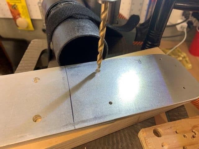
Drilling tap drill holes
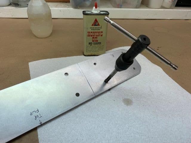
Tapping each hole for 1/4-20 bolts
Finally got the new main spar bolted to internal wing spar on each side. It took some fussing because the holes are never exactly on center when reverse engineering a part like this and also there is a slight angle difference between the two spars. This resulted in having to slightly enlarge the hole in the wing spar and then run the tap through again inside the wing. A major pain but its done. I had to cut the flat head bolts to size from longer bolts. The countersunk flat head is necessary to clear the tire in the wheel well. It all seems to fit OK. The last step will be to cut out the lightening hole between the bolts.
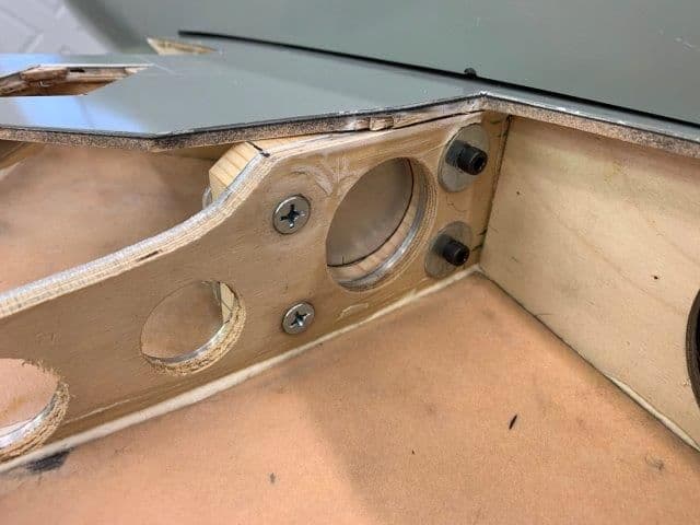
Back side of spar. I elected to tap the holes and thread the bolts in because its very difficult to get a nut and wrench to the inside holes. I am hoping to keep the assembly of the wings as simple as possible. The inside bolts (the important ones) have 1/4" of metal to thread into and the outside are in 1/8" thick metal. All the bolts snug down well. The lightening hole will be between the bolts. This wont be a simple ARF wing assembly but hopefully it will be manageable at the field.
Drilling pilot holes for tap drill
Drilling tap drill holes
Tapping each hole for 1/4-20 bolts
Finally got the new main spar bolted to internal wing spar on each side. It took some fussing because the holes are never exactly on center when reverse engineering a part like this and also there is a slight angle difference between the two spars. This resulted in having to slightly enlarge the hole in the wing spar and then run the tap through again inside the wing. A major pain but its done. I had to cut the flat head bolts to size from longer bolts. The countersunk flat head is necessary to clear the tire in the wheel well. It all seems to fit OK. The last step will be to cut out the lightening hole between the bolts.
Back side of spar. I elected to tap the holes and thread the bolts in because its very difficult to get a nut and wrench to the inside holes. I am hoping to keep the assembly of the wings as simple as possible. The inside bolts (the important ones) have 1/4" of metal to thread into and the outside are in 1/8" thick metal. All the bolts snug down well. The lightening hole will be between the bolts. This wont be a simple ARF wing assembly but hopefully it will be manageable at the field.
Last edited by Viper1GJ; 01-21-2019 at 06:03 PM.
01-22-2019, 04:04 AM
#285


David,
Thanks for the recommendations. I was planning on 2 pins attached to the inside of each rib and blocked in with wood. You can see the blocks on the outside of the ribs just forward of the pivot rod for the existing pins which were imbedded in the rib. I have ground off the blocks that were on the inside of the ribs where I was going to attach the new pins. I was going to hysol everything in place before closing up the stabs.
My pivot tubes are 2024 aluminum 1/2" OD with .120 walls. The walls are almost 1/8" thick. I had not thought of having a solid center core for the pins. I was planning on fastening the pins with into the rods with hysol by sliding them in and out working the hysol inside the holes. That is why I cut such a wide opening so I could push the rod in the stab and then insert the pins after the rod is in place. Then hysol and block everything in place for cure.
Do you think carbon fiber pins would be better than steel? I haven't really thought about the pins much yet. Advice appreciated.
Thanks,
Gary
Thanks for the recommendations. I was planning on 2 pins attached to the inside of each rib and blocked in with wood. You can see the blocks on the outside of the ribs just forward of the pivot rod for the existing pins which were imbedded in the rib. I have ground off the blocks that were on the inside of the ribs where I was going to attach the new pins. I was going to hysol everything in place before closing up the stabs.
My pivot tubes are 2024 aluminum 1/2" OD with .120 walls. The walls are almost 1/8" thick. I had not thought of having a solid center core for the pins. I was planning on fastening the pins with into the rods with hysol by sliding them in and out working the hysol inside the holes. That is why I cut such a wide opening so I could push the rod in the stab and then insert the pins after the rod is in place. Then hysol and block everything in place for cure.
Do you think carbon fiber pins would be better than steel? I haven't really thought about the pins much yet. Advice appreciated.
Thanks,
Gary
David
01-22-2019, 06:51 AM
#286
Banned
Interesting stuff. I'm watching and learning.
My thought would be to slot the tube. Plug the area first with a hard wood dowel. Soak with CA after inserting it. Cut the slot for a 1 inch wide by 2-3 inches long blade. Soak inside of dowel with CA through slot. Blade should be steel to match the tubes. Position should be just inside the root rib of the stab. Build a wing spar type slot into the stab only horizontal in orientation. You could go crazy (IMHO) and cut 2 slots in the tube. One just inside the root rib and one at the end inside the stab. Done right you could make the tube removable and actually use the blades to secure the tube to the stab with screws. But this is complicating things and getting away from the KISS principle.
My thought would be to slot the tube. Plug the area first with a hard wood dowel. Soak with CA after inserting it. Cut the slot for a 1 inch wide by 2-3 inches long blade. Soak inside of dowel with CA through slot. Blade should be steel to match the tubes. Position should be just inside the root rib of the stab. Build a wing spar type slot into the stab only horizontal in orientation. You could go crazy (IMHO) and cut 2 slots in the tube. One just inside the root rib and one at the end inside the stab. Done right you could make the tube removable and actually use the blades to secure the tube to the stab with screws. But this is complicating things and getting away from the KISS principle.
01-22-2019, 06:14 PM
#287
Thread Starter
My Feedback: (20)
The torque must be applied to the stabs by the two ribs. There is no root rib, it's just the airex foam and fiberglass skin and will support nothing. The existing system that I cut off had two wires embedded into the two ribs and capped on each side by lite plywood.
Gary
Gary
01-22-2019, 06:24 PM
#288
Thread Starter
My Feedback: (20)
WIng spar finished.
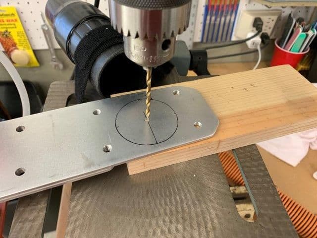
Pilot hole drilled for hole saw cuts
Spar finally finished. Hole saw used to cut circles for lightening holes.
Now we have a real metal spar connecting both wings. Its not likely to break in the middle like the previous system.
View from front bottom

Bolts in wing wheel well showing lightening hole cut out
Spar done!
Many thanks to all who helped me plan and design the spar with recommendations, advice, and support.
Thanks again. Now on to the stab pivot tubes.
Gary
Pilot hole drilled for hole saw cuts
Spar finally finished. Hole saw used to cut circles for lightening holes.
Now we have a real metal spar connecting both wings. Its not likely to break in the middle like the previous system.
View from front bottom
Bolts in wing wheel well showing lightening hole cut out
Spar done!
Many thanks to all who helped me plan and design the spar with recommendations, advice, and support.
Thanks again. Now on to the stab pivot tubes.
Gary
Last edited by Viper1GJ; 01-22-2019 at 06:26 PM.
01-24-2019, 06:01 PM
#289
Thread Starter
My Feedback: (20)
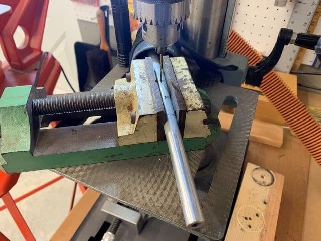
Stab tubes needed to be turned down to a slightly smaller diameter to easily fit into the bearing blocks.
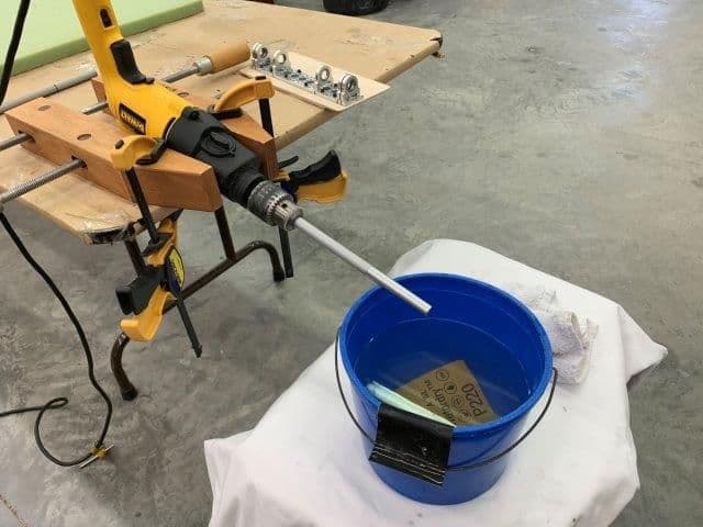
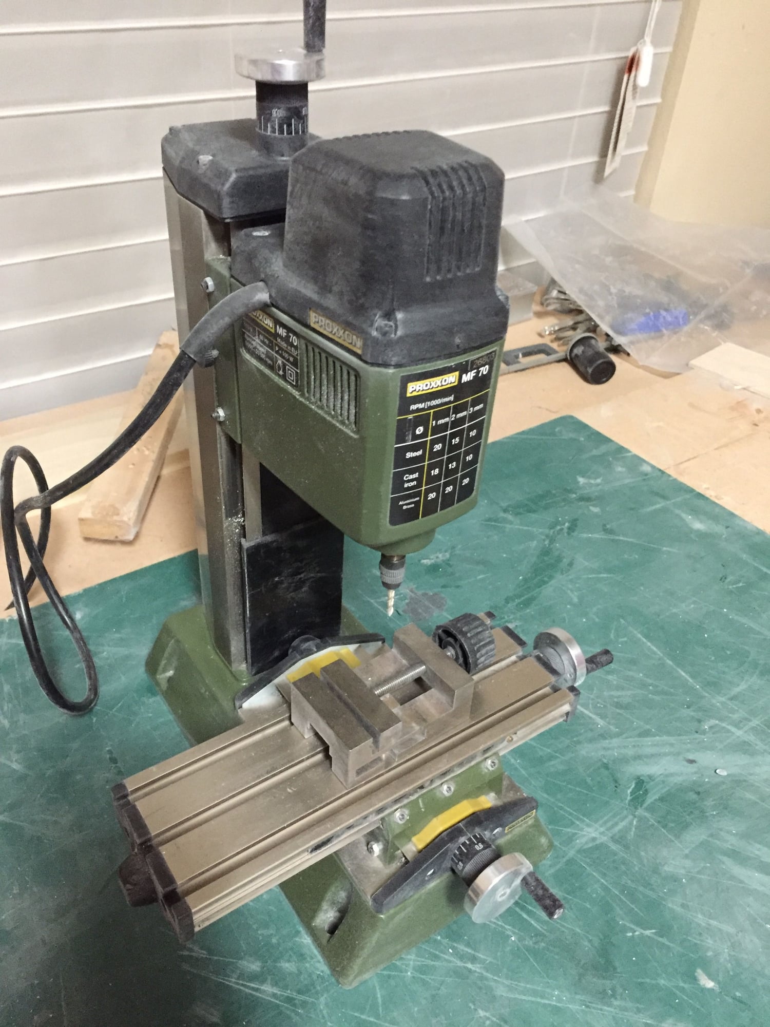
For this task I set up my ultra precision water cooled lathe.

First cuts were made with wet 220 grit paper followed by 400 grit and finally 600 grit.
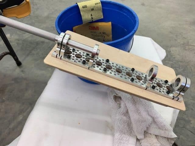
Each tube was turned down to get a good fit into the bearing blocks. The process took about 15 minutes for both tubes.
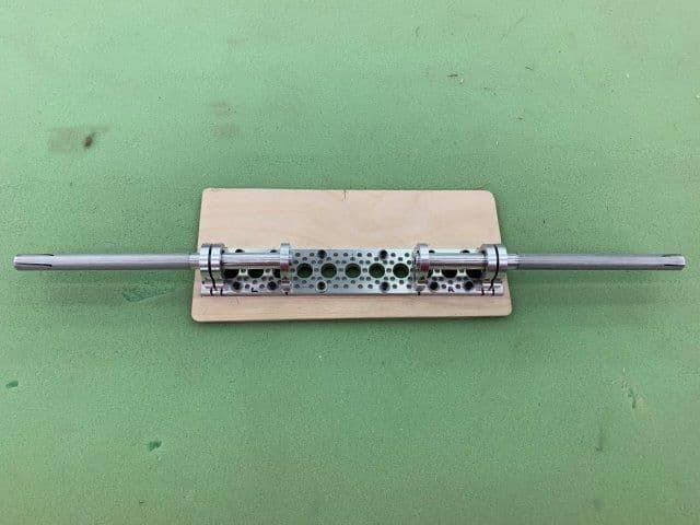
Both tubes fit and ready for mounting in stabs.
For this task I set up my ultra precision water cooled lathe.
First cuts were made with wet 220 grit paper followed by 400 grit and finally 600 grit.
Each tube was turned down to get a good fit into the bearing blocks. The process took about 15 minutes for both tubes.
Both tubes fit and ready for mounting in stabs.
01-24-2019, 06:27 PM
#290
Thread Starter
My Feedback: (20)
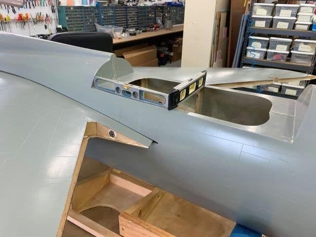
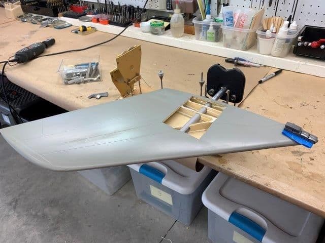
The next step was to properly align the stabs parallel with the wings.
The problem is that the stab root farings are molded into the fuse and are fixed. The stab pivot tube hole is centered in the stab root and is fixed. If you place a tube across the fuse through both holes the tube is not parallel to the wings. Therefore I had to adjust the position of the tube inside the stabs.
Because there are no straight lines anywhere on the airframe I went back to the engine hatch to establish a zero reference like before when setting the wing anhedral.
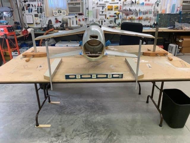
The first step was to install the wings and align the jet with the tables. The tables were shimmed level and framing squares placed at tip of wings and stabs.
Fuse was leveled in pitch and roll axis.
WIng tips were checked for the same height from table. Then the tips of the stabs were checked. Both needed adjustment, left down and right up to get parallel with wings.
I mass balanced the stabs on the pivot tubes to get them to stay level when checking the tips.
After about an hour of trial and error, grinding and sanding, cutting and shimming, I finally got both sides lined up with the wings. The left side required some grinding inside the top skin to lower the tip and the right side required some shims between the tube and the top skin to raise the tip. The tubes now fit tight between the root and the spars between the shims. Next step is to drill the torque transfer rod holes at the inside of the two ribs. The stab root has no rib, its just airex and fiberglass.

Its as good as I can get it.
The problem is that the stab root farings are molded into the fuse and are fixed. The stab pivot tube hole is centered in the stab root and is fixed. If you place a tube across the fuse through both holes the tube is not parallel to the wings. Therefore I had to adjust the position of the tube inside the stabs.
Because there are no straight lines anywhere on the airframe I went back to the engine hatch to establish a zero reference like before when setting the wing anhedral.
The first step was to install the wings and align the jet with the tables. The tables were shimmed level and framing squares placed at tip of wings and stabs.
Fuse was leveled in pitch and roll axis.
WIng tips were checked for the same height from table. Then the tips of the stabs were checked. Both needed adjustment, left down and right up to get parallel with wings.
I mass balanced the stabs on the pivot tubes to get them to stay level when checking the tips.
After about an hour of trial and error, grinding and sanding, cutting and shimming, I finally got both sides lined up with the wings. The left side required some grinding inside the top skin to lower the tip and the right side required some shims between the tube and the top skin to raise the tip. The tubes now fit tight between the root and the spars between the shims. Next step is to drill the torque transfer rod holes at the inside of the two ribs. The stab root has no rib, its just airex and fiberglass.
Its as good as I can get it.
Last edited by Viper1GJ; 01-24-2019 at 06:32 PM.
01-25-2019, 04:21 AM
#291
Banned

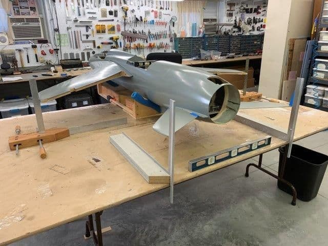
It's looking good there. I hadn't realized just how big that tail pipe is. I don't recall if you've settled on a paint scheme yet. If not, I'd like to throw my vote for a Wild Weasel scheme.
Last edited by Appowner; 01-25-2019 at 04:28 AM.
01-25-2019, 04:58 PM
#292
Thread Starter
My Feedback: (20)
Appowner,
It's amazing what you can do with that ultra precision water cooled lathe!
The picture above has the tail cone removed. There is a good photo of the tail pipe size on post #172
I'm planning on the Vietnam era camo scheme. I have the paint codes for those colors. I may try to get a good photo of a jet from one of my old Air Force squadrons and copy it. Looking for the 13th or 421st Tactical Fighter Squadrons in the 1966-1970 time frame.
However, I plan on test flyjng in grey primer to see if it will work at all before I spend too much effort on the finish.
Gary
01-25-2019, 05:24 PM
#293
Thread Starter
My Feedback: (20)
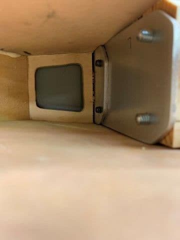
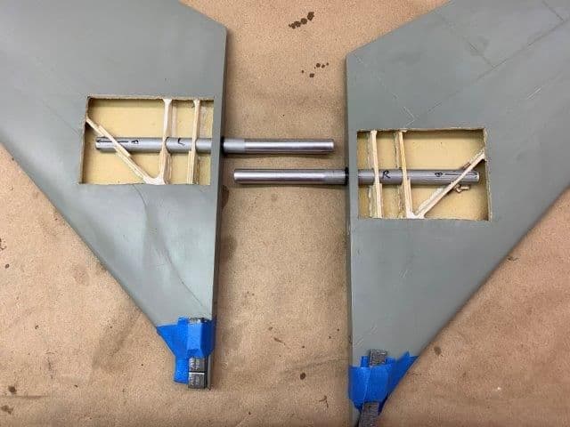
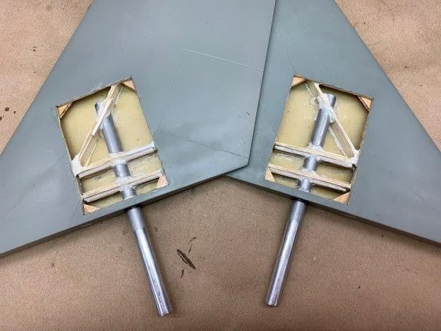
Pivot rods glued into stabs.
Pivot rods drilled for torque transfer rods
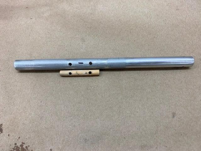
CA hardened dowel was inserted and glued in the center of pivot rods at torque rod location
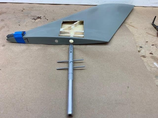
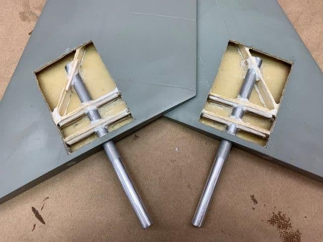
Ready for dry fit into stab. All metal parts were scuffed sanded at joint locations to allow hysol a better grip.

Rods are inserted after pivot tube is in stab and pushed against the two plywood ribs. Final checks were made on the fuse to ensure the shims inside the stabs have the stabs parallel to the wings before hysol was applied.

Hysol applied to all joints and worked inside the torque rod holes and rib holes. Then a fillet layer applied to the outside of all joints.
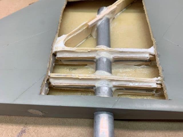
Torque rods are blocked in with 1/8" ply strips on top and bottom
The stabs may flutter, they may blow off the pivot tubes, but I'm pretty sure the torque rods will still be glued on the pivot tube and ribs inside the smoking hole!
Pivot rods drilled for torque transfer rods
CA hardened dowel was inserted and glued in the center of pivot rods at torque rod location
Ready for dry fit into stab. All metal parts were scuffed sanded at joint locations to allow hysol a better grip.
Rods are inserted after pivot tube is in stab and pushed against the two plywood ribs. Final checks were made on the fuse to ensure the shims inside the stabs have the stabs parallel to the wings before hysol was applied.
Hysol applied to all joints and worked inside the torque rod holes and rib holes. Then a fillet layer applied to the outside of all joints.
Torque rods are blocked in with 1/8" ply strips on top and bottom
The stabs may flutter, they may blow off the pivot tubes, but I'm pretty sure the torque rods will still be glued on the pivot tube and ribs inside the smoking hole!
Last edited by Viper1GJ; 01-26-2019 at 03:51 PM.
01-26-2019, 05:26 AM
#294
Banned
Appowner,
It's amazing what you can do with that ultra precision water cooled lathe!
The picture above has the tail cone removed. There is a good photo of the tail pipe size on post #172
I'm planning on the Vietnam era camo scheme. I have the paint codes for those colors. I may try to get a good photo of a jet from one of my old Air Force squadrons and copy it. Looking for the 13th or 421st Tactical Fighter Squadrons in the 1966-1970 time frame.
However, I plan on test flyjng in grey primer to see if it will work at all before I spend too much effort on the finish.
Gary
It's amazing what you can do with that ultra precision water cooled lathe!
The picture above has the tail cone removed. There is a good photo of the tail pipe size on post #172
I'm planning on the Vietnam era camo scheme. I have the paint codes for those colors. I may try to get a good photo of a jet from one of my old Air Force squadrons and copy it. Looking for the 13th or 421st Tactical Fighter Squadrons in the 1966-1970 time frame.
However, I plan on test flyjng in grey primer to see if it will work at all before I spend too much effort on the finish.
Gary
But a heck of a Commander.
01-26-2019, 12:48 PM
#295
Thread Starter
My Feedback: (20)
Appowner, awesome. My high school assistant principle flew F-105s in SE Asia. He was still flying in the Guard in 1970 my senior year. He gave me a tour of the base, sim time, and RSU tour during launch and recovery of F-105s. I still remember the ground shaking during AB take offs.
01-26-2019, 02:04 PM
#296
Thread Starter
My Feedback: (20)
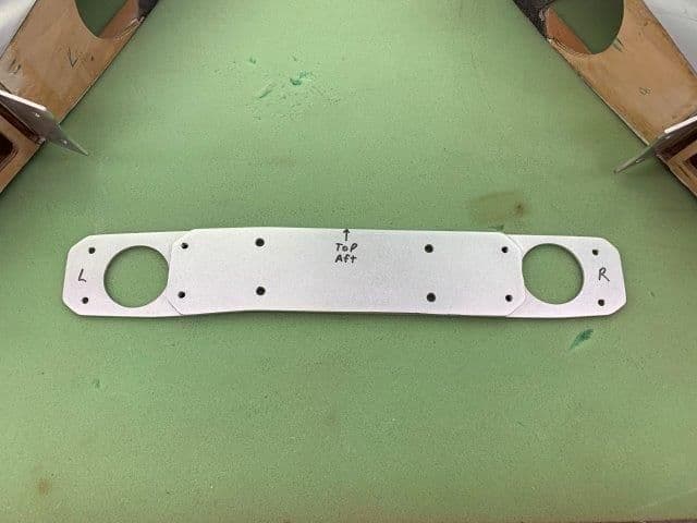
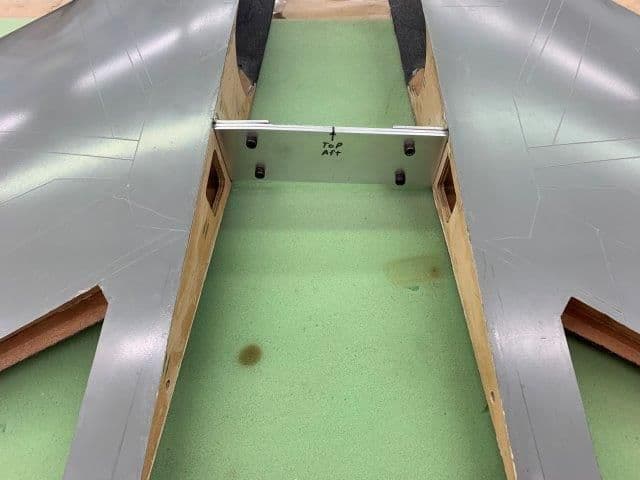
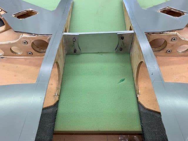
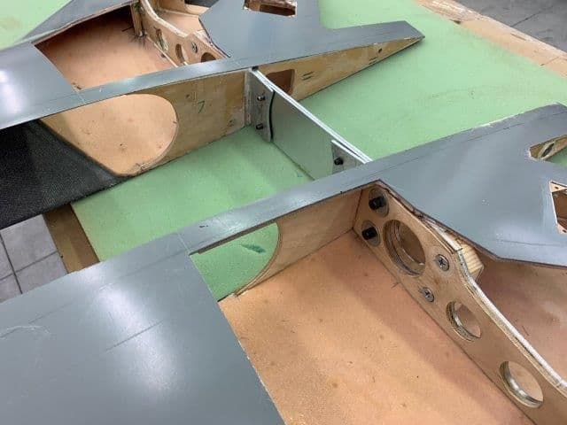
Glued stab mount tray in fuse

Lightening holes cut in stab mounting tray and edge stiffeners fabricated
Hysol laid in joint locations extra thick to fill in less than perfect joint edges

Stab tray laid in and stab pivot rods inserted to ensure alignment during cure. Hysol fillets formed along edges.
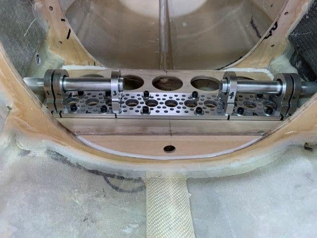
Edge stiffeners added between formers and stab mounting tray
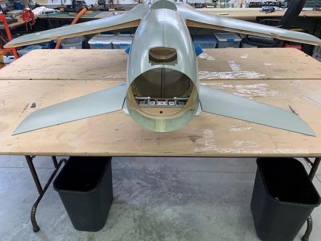
Finally have the stabs mounted!
Lightening holes cut in stab mounting tray and edge stiffeners fabricated
Hysol laid in joint locations extra thick to fill in less than perfect joint edges
Stab tray laid in and stab pivot rods inserted to ensure alignment during cure. Hysol fillets formed along edges.
Edge stiffeners added between formers and stab mounting tray
Finally have the stabs mounted!
01-26-2019, 02:53 PM
#297
Banned
Appowner, awesome. My high school assistant principle flew F-105s in SE Asia. He was still flying in the Guard in 1970 my senior year. He gave me a tour of the base, sim time, and RSU tour during launch and recovery of F-105s. I still remember the ground shaking during AB take offs.
Stabs look good!
01-26-2019, 08:26 PM
#299
Banned
01-29-2019, 05:31 PM
#300
Thread Starter
My Feedback: (20)
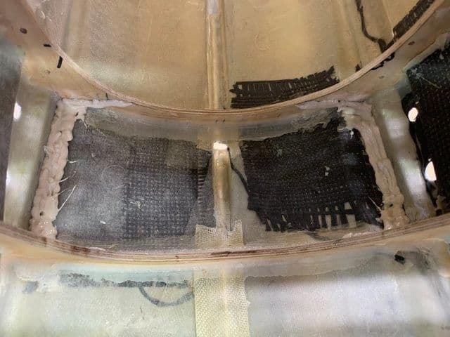
Re skinned bottom of stabs with 3/32" balsa.
Corner gussets glued to inside of bottom stab skins

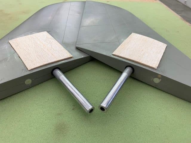
3/32" balsa sheet cut to fit opening and soaked in hot water to help shape curve. Hysol applied to ribs and spar and on inside of each corner gusset. Medium CA was applied to outside of each corner to help tack the balsa down while epoxy cured.
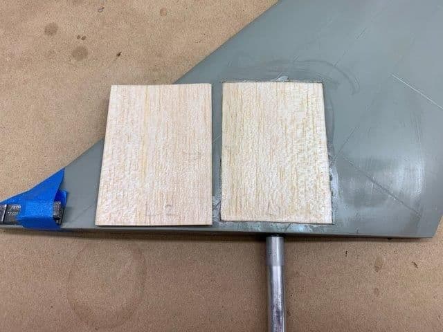
First layer of balsa glued in place and is slightly recessed below the surface of the skin. The edges are glued to the stab skin with thin CA and gaps were filled with 30 min epoxy. Second layer of balsa is soaked in hot water and ready to laminate on top of first layer.
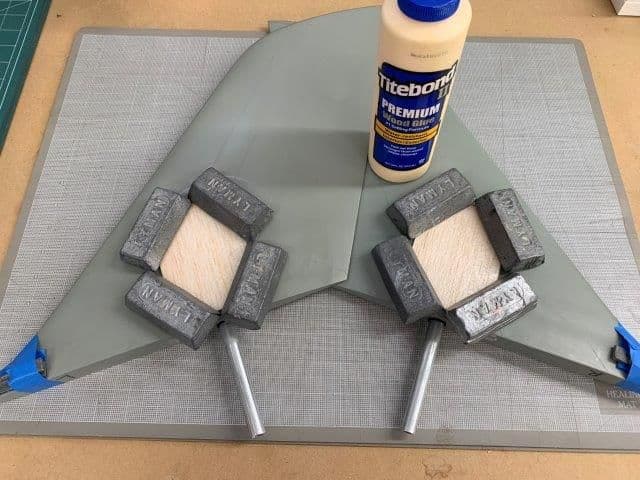
Titebond wood glue use to laminate the second layer due to ease of sanding to final shape. Lead weights held layers together.
All dry and ready for sanding to final shape of stab bottom surface.
Corner gussets glued to inside of bottom stab skins
3/32" balsa sheet cut to fit opening and soaked in hot water to help shape curve. Hysol applied to ribs and spar and on inside of each corner gusset. Medium CA was applied to outside of each corner to help tack the balsa down while epoxy cured.
First layer of balsa glued in place and is slightly recessed below the surface of the skin. The edges are glued to the stab skin with thin CA and gaps were filled with 30 min epoxy. Second layer of balsa is soaked in hot water and ready to laminate on top of first layer.
Titebond wood glue use to laminate the second layer due to ease of sanding to final shape. Lead weights held layers together.
All dry and ready for sanding to final shape of stab bottom surface.