


M548 tracked cargo truck
 08-07-2018, 01:35 PM
#26


 08-07-2018, 02:26 PM
#27
Now to the small opening under the tailgate:
The real one opens but I kept it shut, more simple and allows more space inside:
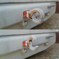
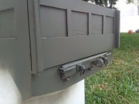
Only the D-rings are 3d printed. Something new to me because it's printed in one piece but they rotate
The real one opens but I kept it shut, more simple and allows more space inside:
Only the D-rings are 3d printed. Something new to me because it's printed in one piece but they rotate
08-08-2018, 11:50 AM
#28
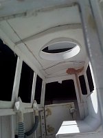
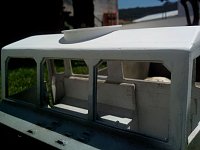
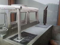
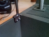
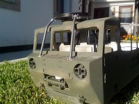
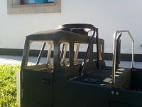
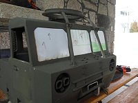
glued the roof and did the opening of the hatch
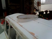
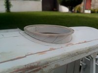
When the windows were cut, didn't notice that the real ones they weren't square. Small detail but bothered me lately...
So I chamfered the top corners
When the windows were cut, didn't notice that the real ones they weren't square. Small detail but bothered me lately...
So I chamfered the top corners

 08-13-2018, 10:36 PM
#33
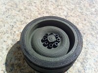
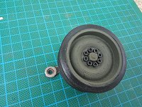
One of the 10 road wheels:
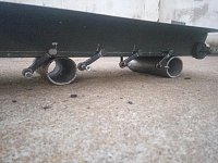
What this will be?
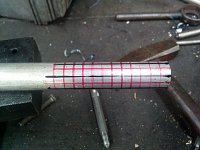
there's more than one kind of stack for this model. I went with this because it's easier to add real smoke in the future
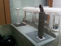
This one is for the intake:
Also made the bezels (?) around the stacks like the 1:1
What this will be?
there's more than one kind of stack for this model. I went with this because it's easier to add real smoke in the future
This one is for the intake:
Also made the bezels (?) around the stacks like the 1:1
08-15-2018, 05:18 AM
#34
Looks great so far!!!
08-15-2018, 09:22 AM
#35
Quick mockup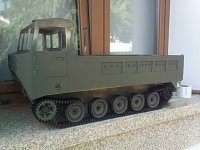
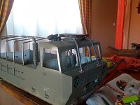
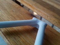
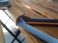
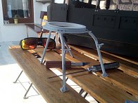
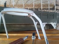
Now, to the canvas frame
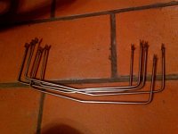
How the hold to the body
All assembled:
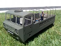
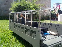

were made in 4mm stainless steel rod, TIG welded and the brackets are from 12mm square tubing. Ran out of M2 nuts in the middle of the assembly
Now, to the canvas frame
How the hold to the body
All assembled:
were made in 4mm stainless steel rod, TIG welded and the brackets are from 12mm square tubing. Ran out of M2 nuts in the middle of the assembly
08-16-2018, 12:28 PM
#36
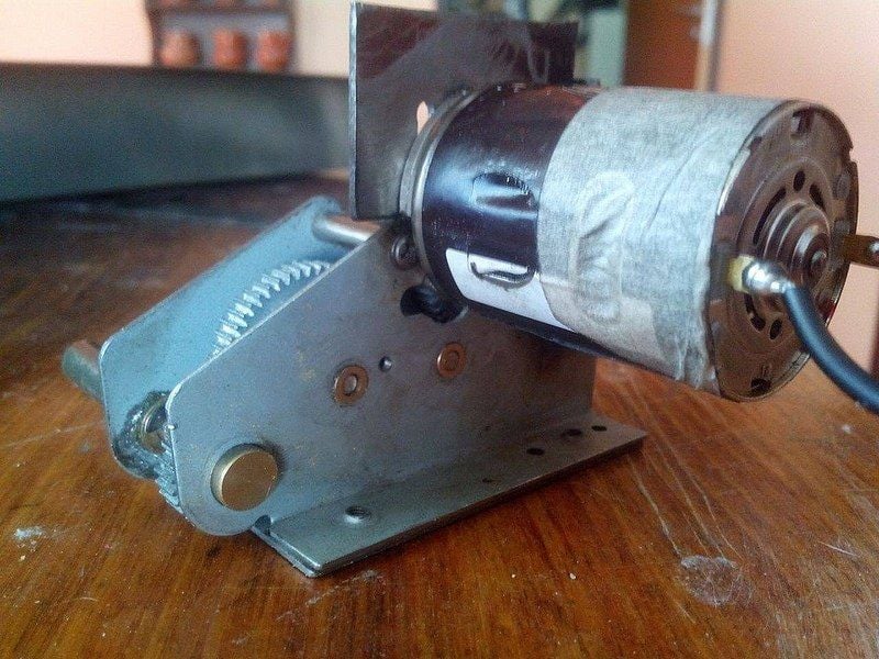
This gearbox was harder to mod than the other but works well(minus the gears made of butter)
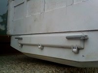
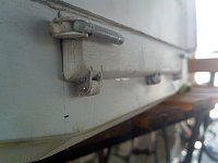
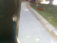
Turned my attention to the tailgate now. Added the steel tow cable with all it's mounts


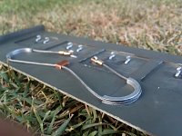
Sure it will look better all painted(and without excess glue) but i want to show it earlier. For the curious, there's aluminium for the half circles and hooks , copper on the middle mount, brass on the cable ends and the cable itself it's steel(a bike brake cable)
Turned my attention to the tailgate now. Added the steel tow cable with all it's mounts
Sure it will look better all painted(and without excess glue) but i want to show it earlier. For the curious, there's aluminium for the half circles and hooks , copper on the middle mount, brass on the cable ends and the cable itself it's steel(a bike brake cable)
08-17-2018, 11:05 PM
#37
Another stage:
Working on the ring mount and legs for the .50.It's a notorious feature that had to include..
The ring it's a 2 piece part that I've machined earlier. Could do it in 1 piece but this way, rotates 360�.
First, the front legs

Then,could do the rear ones

The asymmetry on these is on purpose.For some reason the 1:1 it's like this...
Waited to next day to allow to epoxy to harden and added reinforcements,steps and cleaned the "welds"


Only needs a bit of sanding,colour and better looking(and shorter bolts). I think I'm doing the .50's mount next...
Working on the ring mount and legs for the .50.It's a notorious feature that had to include..
The ring it's a 2 piece part that I've machined earlier. Could do it in 1 piece but this way, rotates 360�.
First, the front legs
Then,could do the rear ones
The asymmetry on these is on purpose.For some reason the 1:1 it's like this...
Waited to next day to allow to epoxy to harden and added reinforcements,steps and cleaned the "welds"
Only needs a bit of sanding,colour and better looking(and shorter bolts). I think I'm doing the .50's mount next...
08-19-2018, 02:11 AM
#38
More stuff :
 First, the cutoff swich
 And then, the handles(?) to help enter the cab
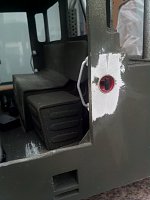 Some creative liberty to make them work with the door handles
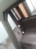 Also...painted the last 5 road wheels
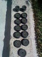
08-22-2018, 03:30 PM
#39
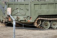
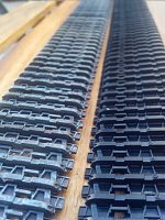
While i wait for my m548 to return from the seamstress I'm doing other stuff. One of those are taking care of the tracks. Stock, look too clean and being all black,don't seem scale. So i tried to weather them to look metallic and worn
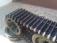
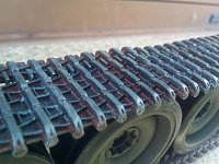
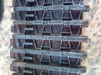
this is the first one, used a rust red, and 2 different grays
because the red was too "red" for rust, on the second track applied a bit of dark brown and seems better
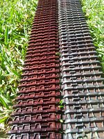

Stock and weathered:
this is the first one, used a rust red, and 2 different grays
because the red was too "red" for rust, on the second track applied a bit of dark brown and seems better
Stock and weathered:
08-23-2018, 11:37 AM
#40
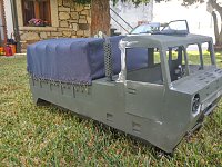
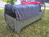
My attempt at a canvas for the bed
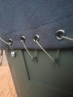
About the random wiring and unused holes,the hooks don't have even spacing between them so i add a couple more holes for keep them even spaced. The eyelets are 3m and had to modify the plier to that small size. The canvas it's not green but i've seen them this color on some photos.
There's also a tarp for the hatch in the roof
08-25-2018, 12:07 PM
#42
Thanks!
Now, the suspension system:
The m548 uses torsion bars as suspension system with additional shocks on the first and last wheel

Not a m548 but you get the idea
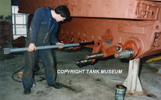
On a m113

the traction bars rely on long rods that are fixed in one end and can twist to provide suspension. Many small cars still use that as rear axle.
After some research and failed attempts, decided to replicate the 1:1 as good as I could
Prototype:
These pieces are where the axles and springs are mounted


The photos are a bit confusing but the 8x 4mm rods are the pivots for each wheel and the wires are spring steel, later switched to a kind of spring blade
The advantages of this system are that can be easily adjusted in stiffness and ride height
Unfortunately, the first wheel on each side cannot be included on this system because the motors were in the way. The solution was putting a shock on the outside. Don't look out of place as the 1:1 has one too
An funny feature it's that, by the design of system,with torsion bars next to each other, wheels are slightly offset from one side to another. Hard to notice but the 1:1 it's also like this
Now, the suspension system:
The m548 uses torsion bars as suspension system with additional shocks on the first and last wheel
Not a m548 but you get the idea
On a m113
the traction bars rely on long rods that are fixed in one end and can twist to provide suspension. Many small cars still use that as rear axle.
After some research and failed attempts, decided to replicate the 1:1 as good as I could
Prototype:
These pieces are where the axles and springs are mounted
The photos are a bit confusing but the 8x 4mm rods are the pivots for each wheel and the wires are spring steel, later switched to a kind of spring blade
The advantages of this system are that can be easily adjusted in stiffness and ride height
Unfortunately, the first wheel on each side cannot be included on this system because the motors were in the way. The solution was putting a shock on the outside. Don't look out of place as the 1:1 has one too
An funny feature it's that, by the design of system,with torsion bars next to each other, wheels are slightly offset from one side to another. Hard to notice but the 1:1 it's also like this
08-28-2018, 12:17 PM
#43
The suspension arms. The real ones are a kind of dogbone so have to do them similar.
They are steel bar with one washer welded at each end to add that 3d look and help to round the ends. Machined a bit on the center to make it thinner. Then, filed all the edges to look a cast piece. On the holes at the ends, will be a axle for the wheel and on the other, the suspension pivot
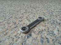
In the end, they'll be almost invisible. Half-hidden by the wheels and the tracks
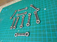
Doesn't show much...
They are steel bar with one washer welded at each end to add that 3d look and help to round the ends. Machined a bit on the center to make it thinner. Then, filed all the edges to look a cast piece. On the holes at the ends, will be a axle for the wheel and on the other, the suspension pivot
In the end, they'll be almost invisible. Half-hidden by the wheels and the tracks
Doesn't show much...
08-30-2018, 01:28 PM
#44
4 arms in place
4 wheels in place

Only 4 wheels per side in that photo. The first pair of road wheels have a different suspension setup than the other ones. Settled on a simple design. A pivot bolted to the chassis where the arm rotates(ball bearings) and a shock. The 1:1 also has a shock on the first arm, assisting the torsion bar, so this it's not unrealistic
Mock-up:
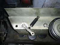
Not happy with this shock so I've made my one:
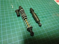
It's an axial scx10 shock, gone from 93mm to 62mm,53mm compressed and 71mm extended. Shorter shaft and a "cap" hidding it to look more scale. On the next post, I'll show them mounted and a video of it working
4 wheels in place
Only 4 wheels per side in that photo. The first pair of road wheels have a different suspension setup than the other ones. Settled on a simple design. A pivot bolted to the chassis where the arm rotates(ball bearings) and a shock. The 1:1 also has a shock on the first arm, assisting the torsion bar, so this it's not unrealistic
Mock-up:
Not happy with this shock so I've made my one:
It's an axial scx10 shock, gone from 93mm to 62mm,53mm compressed and 71mm extended. Shorter shaft and a "cap" hidding it to look more scale. On the next post, I'll show them mounted and a video of it working
08-31-2018, 08:08 AM
#45
Nice work on the suspension!!!
09-01-2018, 03:11 PM
#46
09-04-2018, 04:40 PM
#48
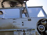
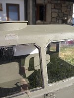
The bodywork is almost complete and it's time to do the "glass". 1mm lexan for the straight ones and for the corners, used a heat gun to "bent" the lexan into a round shape

Did an experiment of "3d cheating" the rubber for the windows:
It's rubber,alright:

taped to the window frame:
Did an experiment of "3d cheating" the rubber for the windows:
It's rubber,alright:
taped to the window frame:
09-05-2018, 11:08 AM
#49
That window frame rubber looks great!!!
09-07-2018, 04:43 AM
#50
Thanks maus45!
more small stuff:
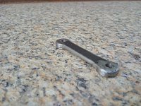
Take a aluminium welding rod

Hammer it a couple times, bit a filing and sanding and voila:

what it could be?

This is my first try with 1.5mm spring wire on the suspension:
Seems good but the steel don't return to the original position. A retired machinist gave me today a couple meters of spring steel in rectangular profile instead of wire. Gonna try that out
more small stuff:
Take a aluminium welding rod
Hammer it a couple times, bit a filing and sanding and voila:
what it could be?
This is my first try with 1.5mm spring wire on the suspension:
Seems good but the steel don't return to the original position. A retired machinist gave me today a couple meters of spring steel in rectangular profile instead of wire. Gonna try that out