1/6 F-105 Build Thread
 09-04-2018, 04:48 PM
#26

Thread Starter
My Feedback: (20)
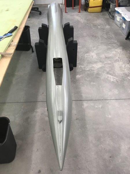
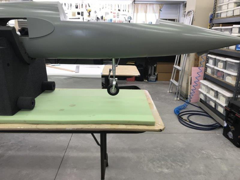
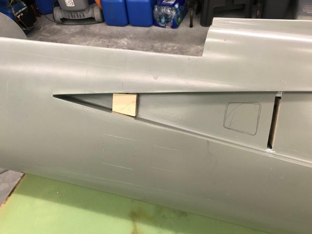
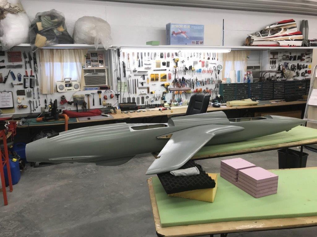
Cutting Nose Gear Well
I cut out the nose gear well using a razor saw and flush cut saw. My kit did not come with nose gear doors and I'm not sure if there are any. Larry is looking to see if there are some in his kit parts. If not I will use the nose gear well cut outs as doors so I wanted a thin kerf so I used the razor saw instead of the Dremel cutting wheel.
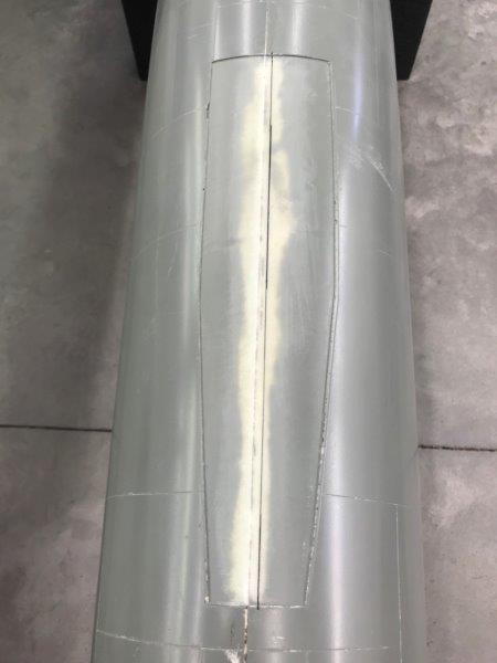
The seam line is not the center line so center line was marked after sanding the seam line smooth. I wanted to do the rough sanding before cutting because it would be easier to hold the fuse rather than the small cutout.
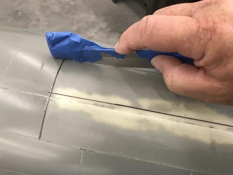
Razor saw with pads taped on help hold on to it.
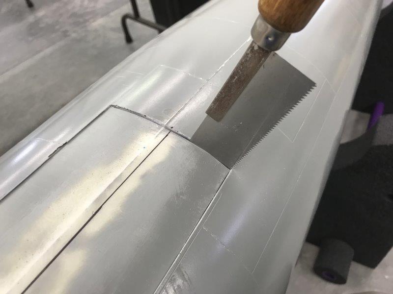
Corners cut with thin flush cut saw
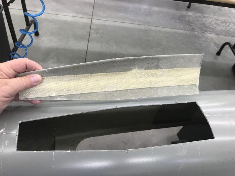
Gear well cut out removed and edges sanded smooth
The seam line is not the fuse centerline. Easy to see on the gun camera housing.
I cut out the nose gear well using a razor saw and flush cut saw. My kit did not come with nose gear doors and I'm not sure if there are any. Larry is looking to see if there are some in his kit parts. If not I will use the nose gear well cut outs as doors so I wanted a thin kerf so I used the razor saw instead of the Dremel cutting wheel.
The seam line is not the center line so center line was marked after sanding the seam line smooth. I wanted to do the rough sanding before cutting because it would be easier to hold the fuse rather than the small cutout.
Razor saw with pads taped on help hold on to it.
Corners cut with thin flush cut saw
Gear well cut out removed and edges sanded smooth
The seam line is not the fuse centerline. Easy to see on the gun camera housing.

 09-04-2018, 05:04 PM
#28
Thread Starter
My Feedback: (20)
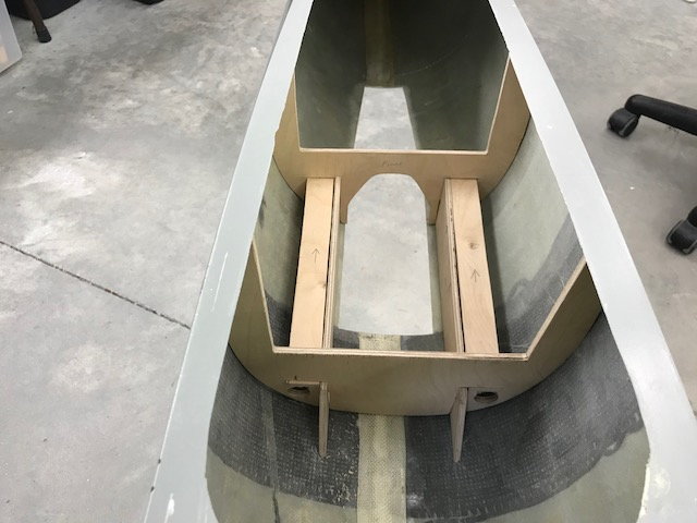
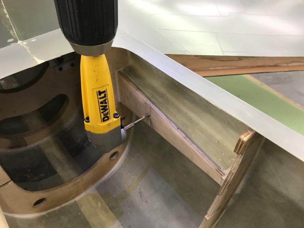
Designing Gear Mounts
I copied the gear mount design from a photo of the kit built by Fighteraces in England. I planned the layout using measurements from the formers that came with the kit that were balsa cores. I then cut fan fold foam parts to mock up and see if my plan worked. Most of the time was spent just thinking it through and drawing. Cutting the foam parts went pretty fast.
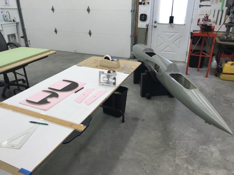
Planning the parts layout and measuring existing parts
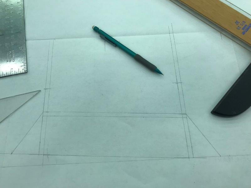
Side view drawing of gear mount beams and formers
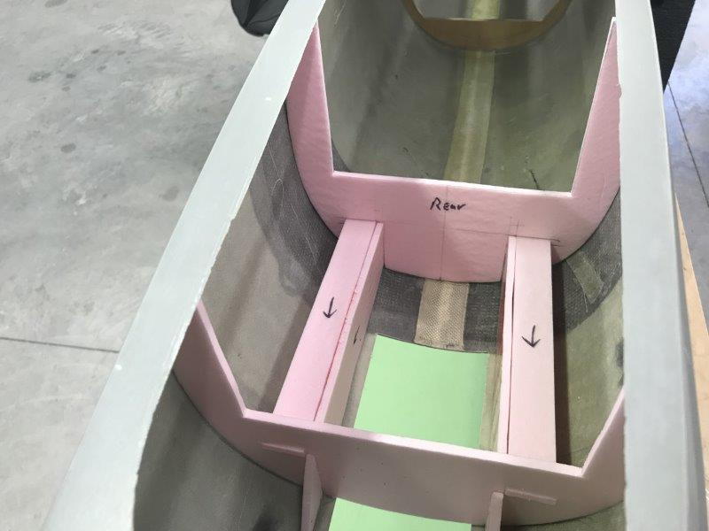
Test fit of mock up parts
Took a couple of tries cutting the mount angle to get the 2-3 degrees forward slant.
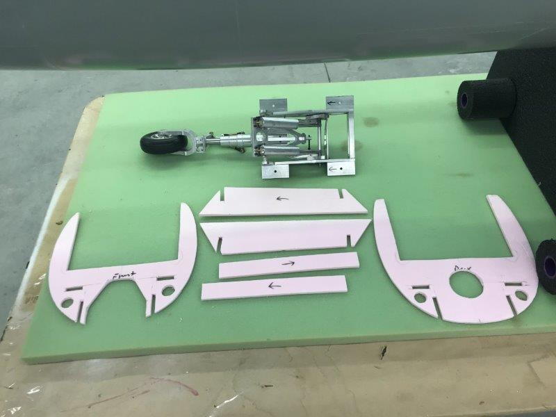
Final parts ready for mock up
Gear test fit on mock up. Cutting wood parts s next.
I copied the gear mount design from a photo of the kit built by Fighteraces in England. I planned the layout using measurements from the formers that came with the kit that were balsa cores. I then cut fan fold foam parts to mock up and see if my plan worked. Most of the time was spent just thinking it through and drawing. Cutting the foam parts went pretty fast.
Planning the parts layout and measuring existing parts
Side view drawing of gear mount beams and formers
Test fit of mock up parts
Took a couple of tries cutting the mount angle to get the 2-3 degrees forward slant.
Final parts ready for mock up
Gear test fit on mock up. Cutting wood parts s next.

 09-05-2018, 06:13 AM
#33
Thread Starter
My Feedback: (20)
LOL..feels like master hacker, not the computer kind. Thx. Gary
Just realized I have to plan space for the rear gear door hinges. Will have to make a relief cut out in the beams for them. Also a biggie is the ground pitch stance. I’ll have to put in wings and check to make sure there is a neutral or positive pitch attitude on ground before I glue in the nose gear mounts.
Just realized I have to plan space for the rear gear door hinges. Will have to make a relief cut out in the beams for them. Also a biggie is the ground pitch stance. I’ll have to put in wings and check to make sure there is a neutral or positive pitch attitude on ground before I glue in the nose gear mounts.
09-05-2018, 09:02 AM
#35
 09-12-2018, 06:03 AM
#38
 09-12-2018, 05:45 PM
#40
Thread Starter
My Feedback: (20)
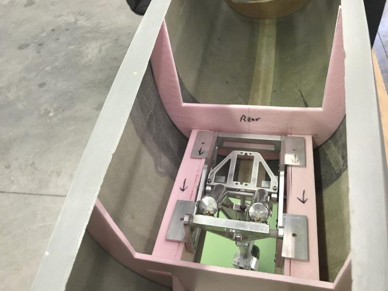
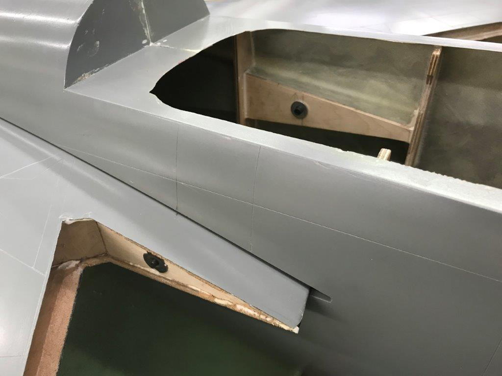
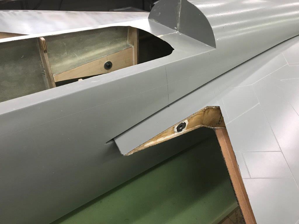
Finally got back to shop today after finishing all the hurricane Florence prep around the house and got the nose gear mounting templates cut out of wood for a dry fit. I will not glue them in until I get the nose gear door hinges and can determine the size of the relief cut outs for the hinges. The dry fit will allow temporary install of the nose gear for checking the toe in angle of the main gear which is where all the work so far is going.
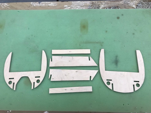
Rough cuts of nose gear mounts
First dry fit.
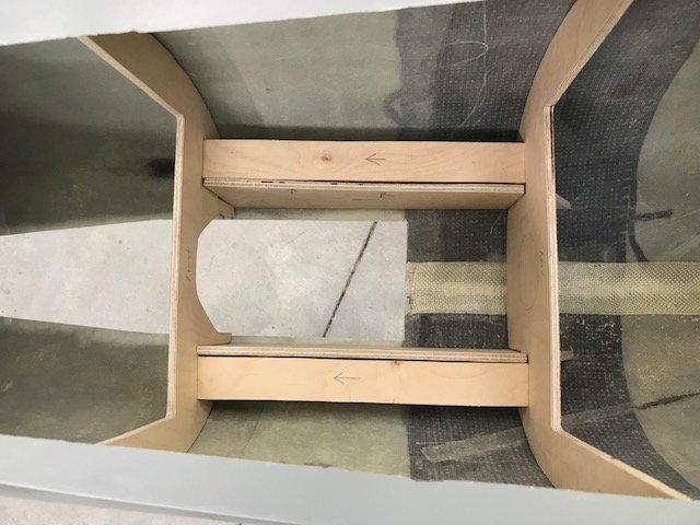
Formers had to be sanded some to get correct fit and bottom of vertical rails hand to be rounded to fit bottom of fuse
Nose gear dry fit.
Rough cuts of nose gear mounts
First dry fit.
Formers had to be sanded some to get correct fit and bottom of vertical rails hand to be rounded to fit bottom of fuse
Nose gear dry fit.
Last edited by Viper1GJ; 09-12-2018 at 05:47 PM.
09-13-2018, 04:39 PM
#42
Thread Starter
My Feedback: (20)
Yea, your correct but the holes are just the pre drilled ones. I’ll drill actual mounting holes later. I just “tacked” the NG in place with existing holes so I can get it on the wheels to check main toe in and NG height for correct pitch on ground.
Thanks. Keep your eyes peeled in case I do something dumb. I can use all the help I can get.
I think I’m actually the second owner after Joe. I know he had five at one time. Not sure what he still has.
Thanks. Keep your eyes peeled in case I do something dumb. I can use all the help I can get.
I think I’m actually the second owner after Joe. I know he had five at one time. Not sure what he still has.
09-15-2018, 04:38 PM
#45
Thread Starter
My Feedback: (20)
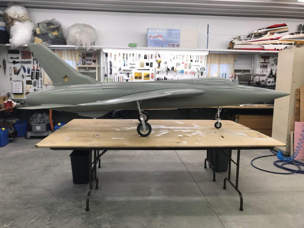
Next steps are to install the wing trailing edge hard mounts. Still working toward getting the jet on the wheels to check the gear toe in.
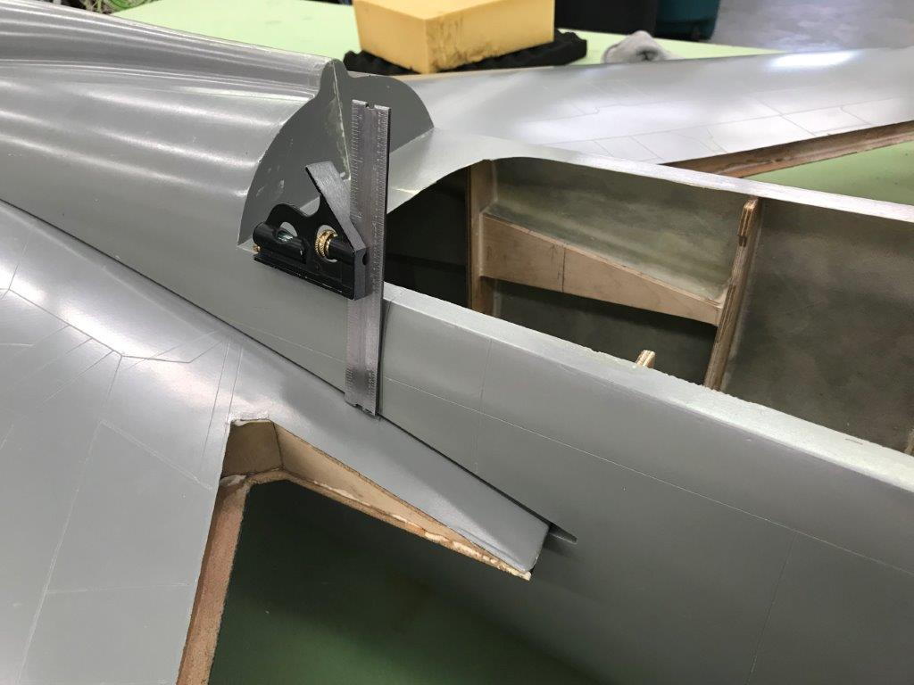
Projecting the location of the trailing edge wing bolt. The plan is to drill all the way through the wing root to the flap side and install a 10-32 blind nut.
There is a 1/4" gap between the fuse and wing root when the wing is bolted on. I installed a spacer so the bolt will hold the wing firm with out pulling it in.

Pilot hole drilled from outside in spacer location
Wings installed and bolt hole drilled from inside out through wing root
10-32 blind nut installed with bolt
Blind nuts secured with hysol
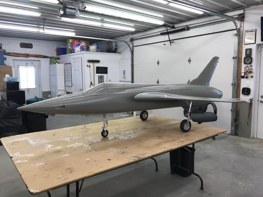
Wings installed ready to mount gear
Projecting the location of the trailing edge wing bolt. The plan is to drill all the way through the wing root to the flap side and install a 10-32 blind nut.
There is a 1/4" gap between the fuse and wing root when the wing is bolted on. I installed a spacer so the bolt will hold the wing firm with out pulling it in.
Pilot hole drilled from outside in spacer location
Wings installed and bolt hole drilled from inside out through wing root
10-32 blind nut installed with bolt
Blind nuts secured with hysol
Wings installed ready to mount gear
09-15-2018, 05:06 PM
#47
Thread Starter
My Feedback: (20)
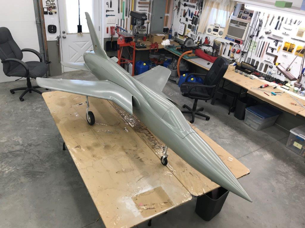
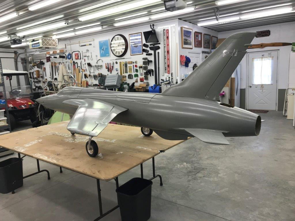
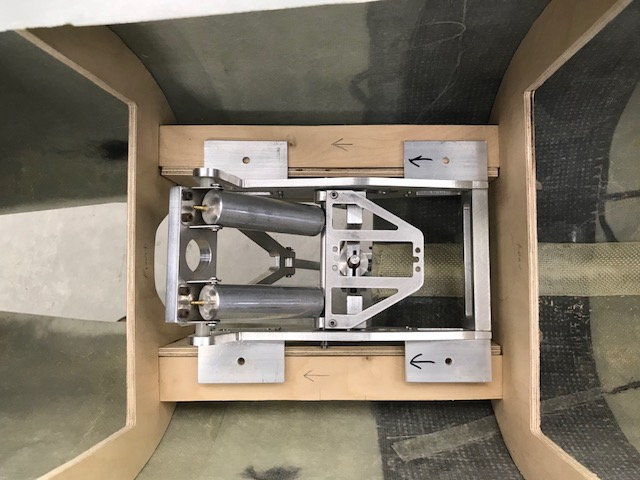
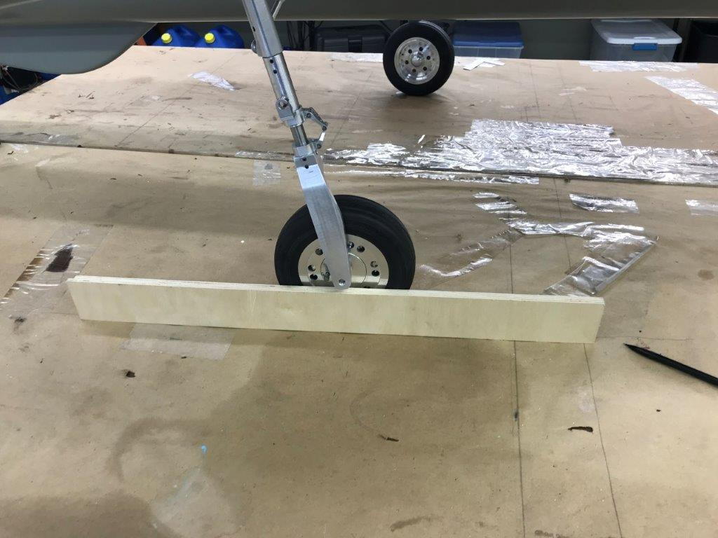
Next step is install gear and get it on the gear. Then check the ground pitch attitude and then main gear tow in.
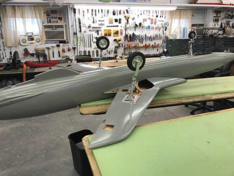
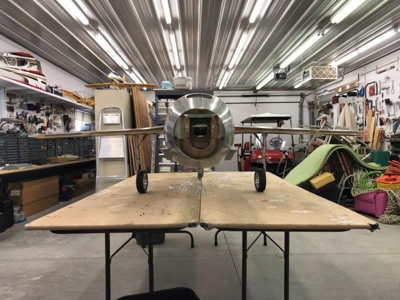
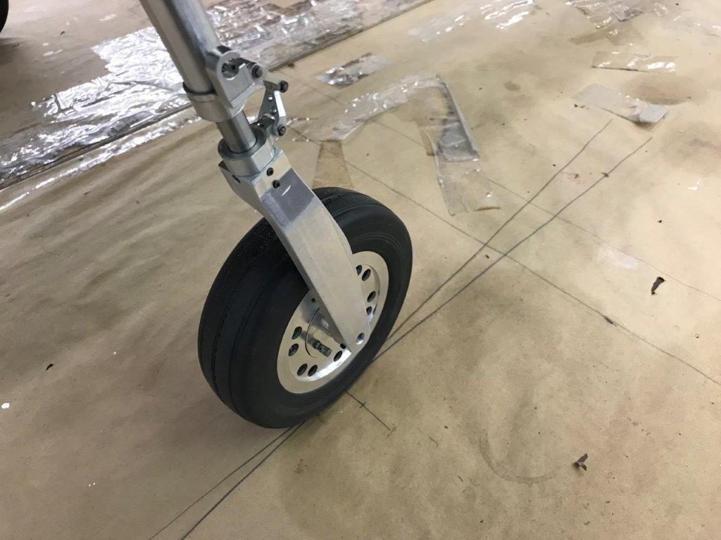
Main gear installed
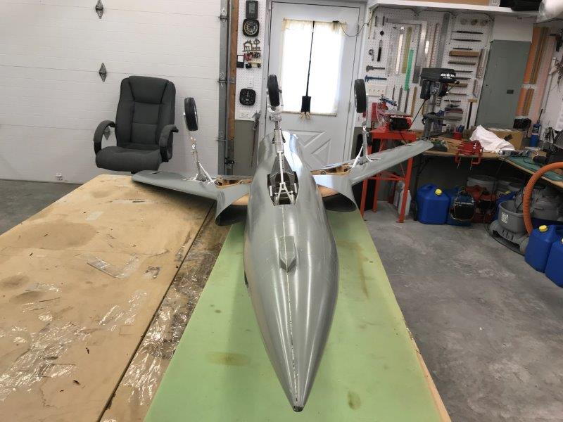
The gear looks huge, just like the real ones
First look on the the wheels, it sits real tall and the main gear has lots of toe in...bad.
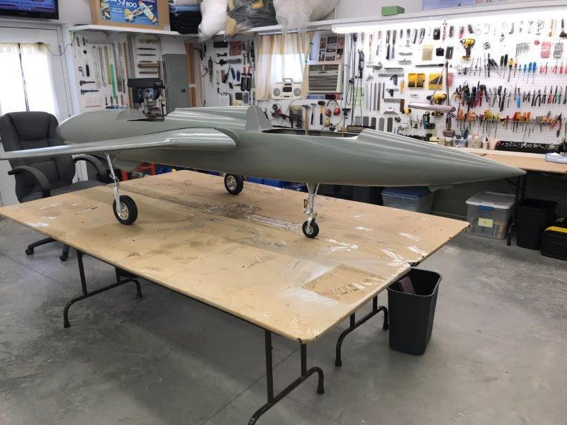
Happy snap on wheels
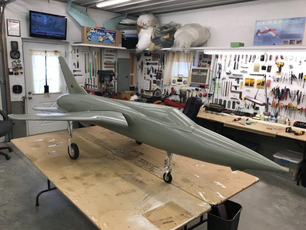
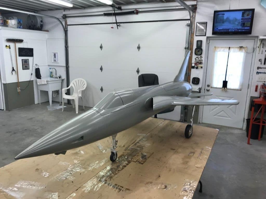
Ground pitch attitude is slightly positive so the nose gear mounts are ok.
The nose gear strut is slightly forward as planned from the three views I have.
View from the rear
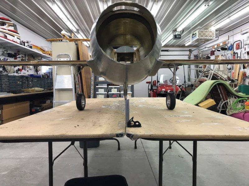
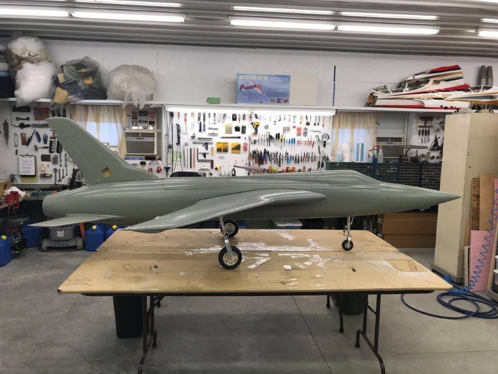
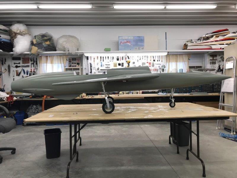
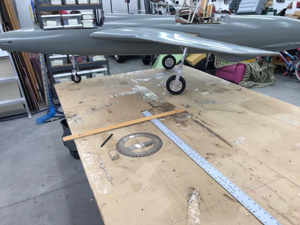
Aligning the fuse parallel to the tables to get a center line to check the main gear toe in
Fuse aligned and centered on table ready to mark the gear toe in angles
Main gear installed
The gear looks huge, just like the real ones
First look on the the wheels, it sits real tall and the main gear has lots of toe in...bad.
Happy snap on wheels
Ground pitch attitude is slightly positive so the nose gear mounts are ok.
The nose gear strut is slightly forward as planned from the three views I have.
View from the rear
Aligning the fuse parallel to the tables to get a center line to check the main gear toe in
Fuse aligned and centered on table ready to mark the gear toe in angles
09-15-2018, 05:30 PM
#48
Thread Starter
My Feedback: (20)
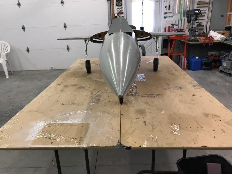
I found the main gear toe in angle to be excessive on both sides. Still not sure how to fix the problem yet.
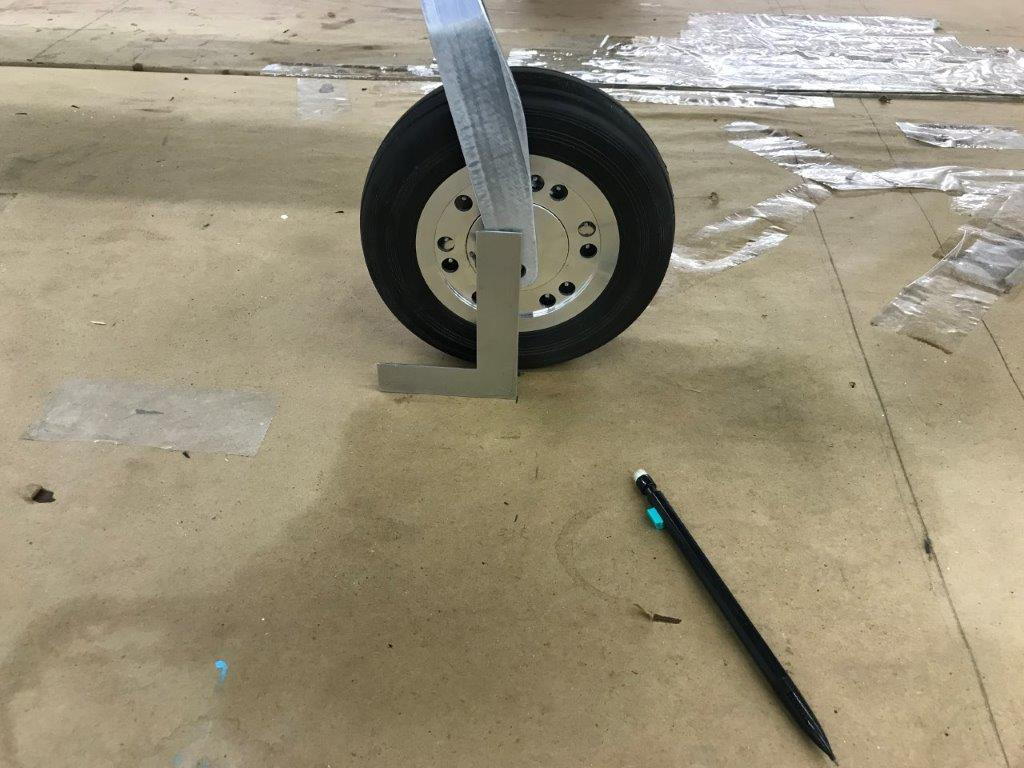
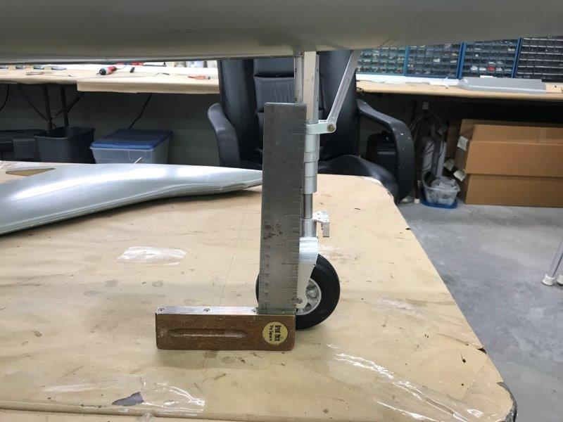
Projecting wheel axle location to table
Marking tow in angle line parallel to tire
Marking line parallel to fuse through the wheel axle location

Measuring angle of toe in
Right main wheel has 6 degrees toe in
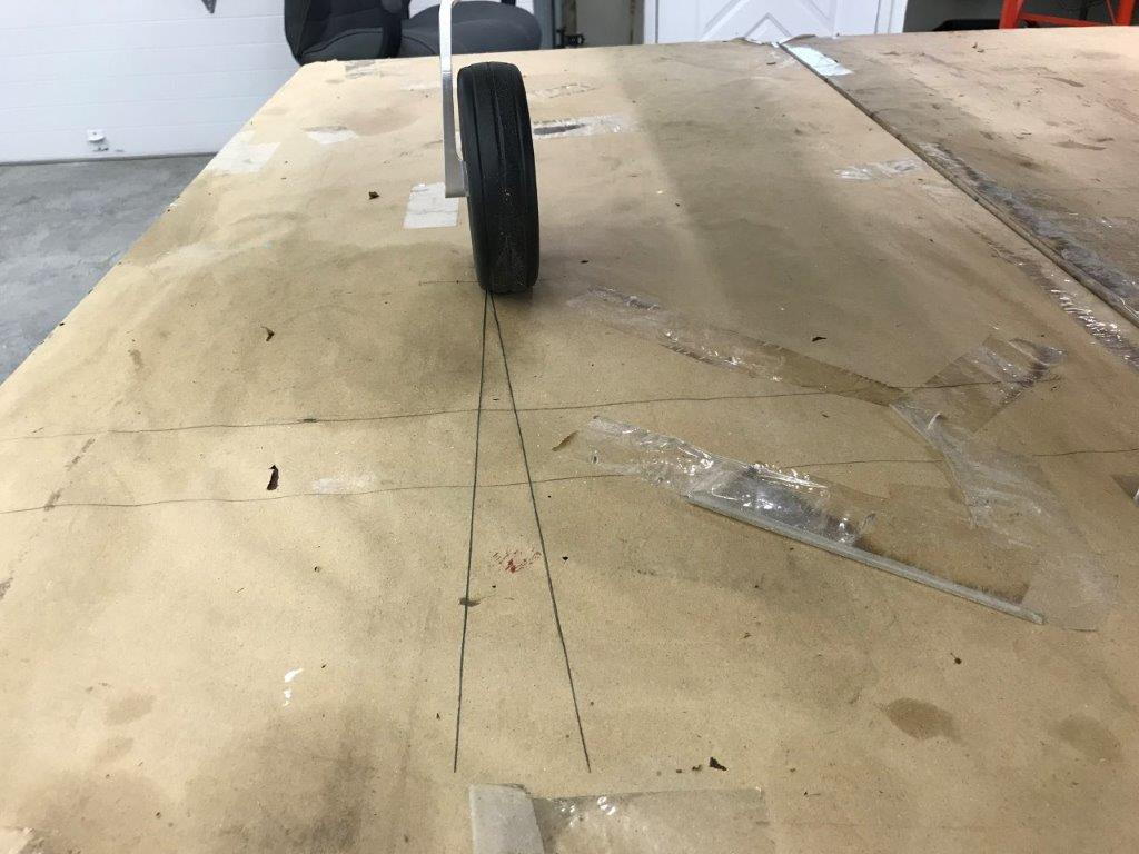
Excessive toe in
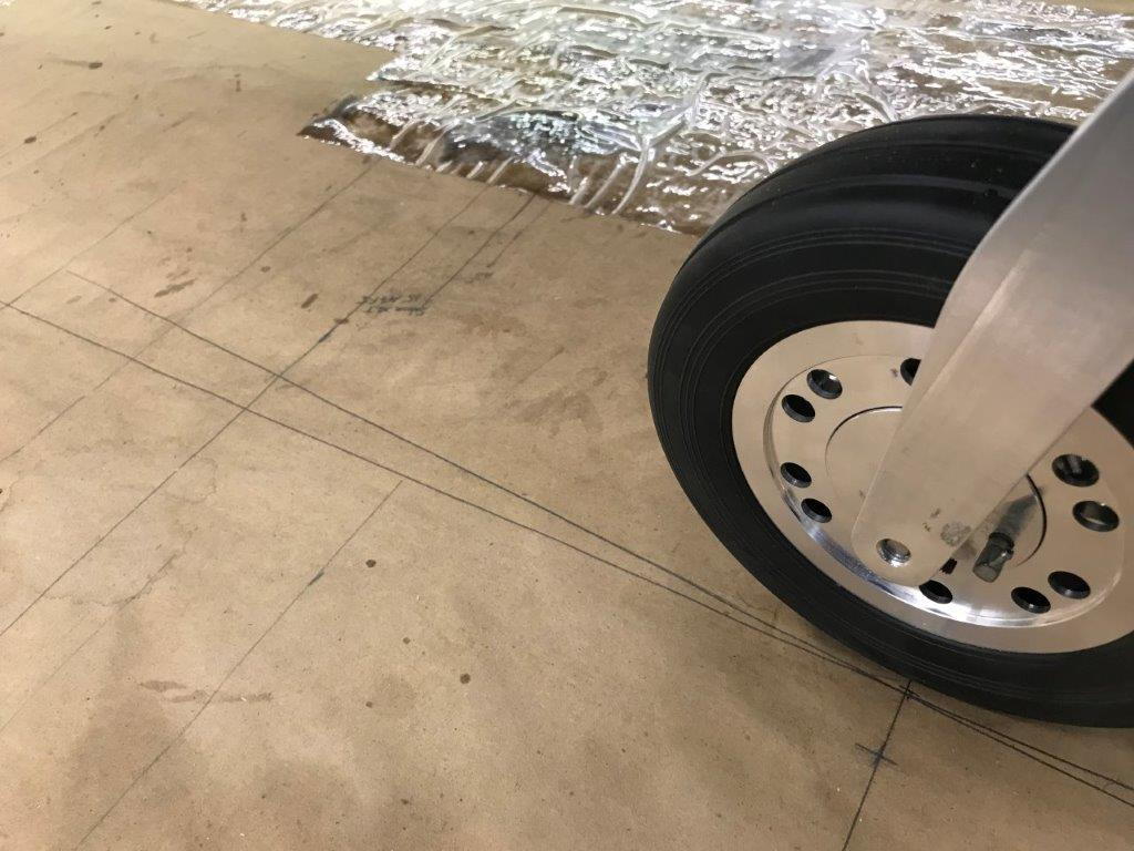
Left main has 5 degrees

Excessive on left also
Projecting wheel axle location to table
Marking tow in angle line parallel to tire
Marking line parallel to fuse through the wheel axle location
Measuring angle of toe in
Right main wheel has 6 degrees toe in
Excessive toe in
Left main has 5 degrees
Excessive on left also
Last edited by Viper1GJ; 09-15-2018 at 05:37 PM.
09-15-2018, 05:57 PM
#49
Thread Starter
My Feedback: (20)
After checking the main gear toe in I got a little discourage and and hurricane Florence was approaching so I decided to stop working and make the F-105 a static display for now. This is when I experienced a little scratch building humor.
..
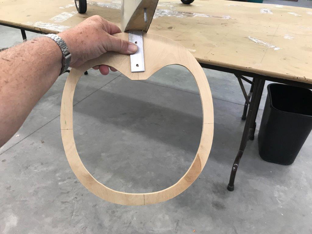
The fin spar blade attaches to a plywood former inside.
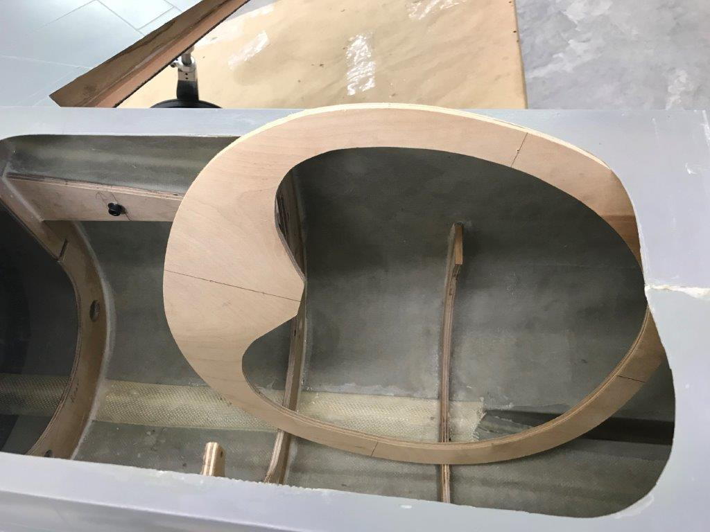
OOPS I followed the "instructions" but must have skipped this step...the former will not fit into the tail after the aft turbine rail half former is installed. Note to all you guys building your F-105s don't install the half former until you install the fin former...just in case you wanted to know.
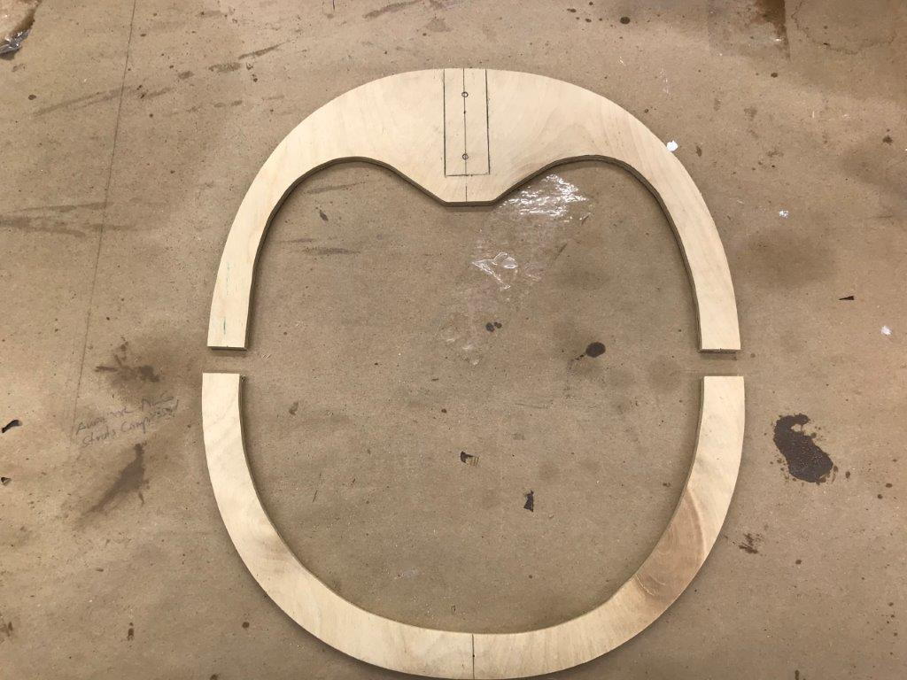
Solution is cut the former in half.
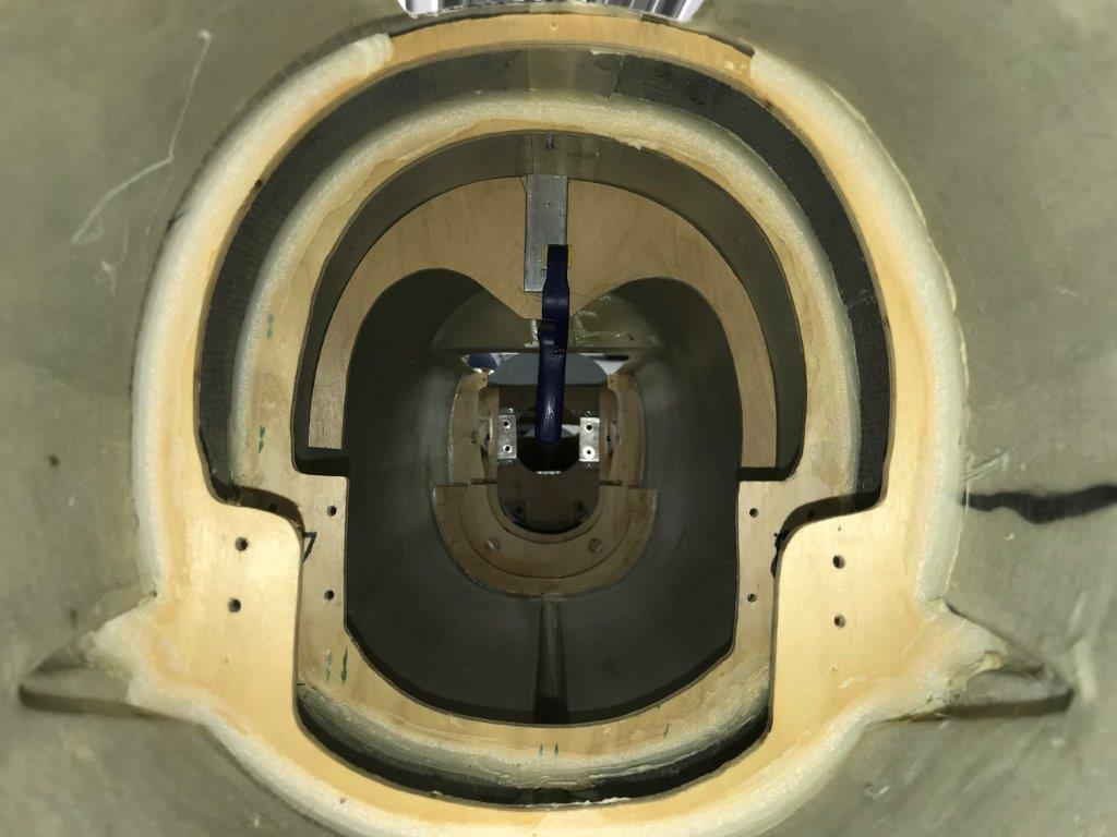
Half former inserted and fin spar clamped on. Good enough to look at for now
..
The fin spar blade attaches to a plywood former inside.
OOPS I followed the "instructions" but must have skipped this step...the former will not fit into the tail after the aft turbine rail half former is installed. Note to all you guys building your F-105s don't install the half former until you install the fin former...just in case you wanted to know.
Solution is cut the former in half.
Half former inserted and fin spar clamped on. Good enough to look at for now