


1/4 Scale Pfalz DIIIa
 01-07-2018, 08:46 PM
#1

Thread Starter

After some years of collecting documentation, asking questions and doodling plans I've decided that it is time to pony up and build a Pfalz DIIIa. One of my objectives in this is to build a scale model to my own plans. There are people who follow the "building for God" school of modeling technique and who produce beautiful museum scale models. This probably won't be one of those. I'm shooting for more of a Pfalz shaped object. My design goal is to produce something along the lines of a BUSA product. That is to say, recognizably scale but with some compromises to ease construction and setup at the field. The thread started by Abufletcher and the pictures of Seth Hunter's efforts have been an encouragement. If one felt the need to duplicate the wickelrumpf construction it would be possible on my design by applying a veneer of 1/64th ply strips to the fuselage but at least at this point, I'm not feeling the desire to do so. The reason is that in most photos of the aircraft the veneer strips do not show. Although I am shooting for a scale outline and will be adding some scale detail this will primarily be a sport flier and not a competition airplane. If it turns out well enough to take to a local fun fly or a local dawn patrol I will be happy. As for the scale outline, one of the main resources, the Wylam drawings have been criticized for their inaccuracies. All the same they are still among the most detailed drawings out there. I have tried to use other sources where possible. The Herris book, "Pfalz Aircraft of WWI" is a great item to have as is the Windsock datafile by P.M. Grosz. The forums on the Aerodrome website have also been helpful. In particular there is an individual who is engaged in producing a set of 3d drawings of the full scale aircraft. Using these sources I have tried to correct the outline as much as possible. I wish I could remember which thread I saw this bit of sage advice in; "Sometimes there just isn't good documentation. You just have to suck it up and build the best you can".
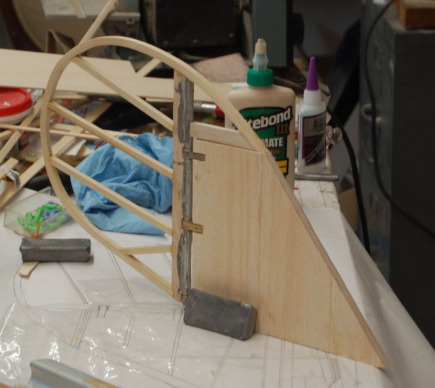
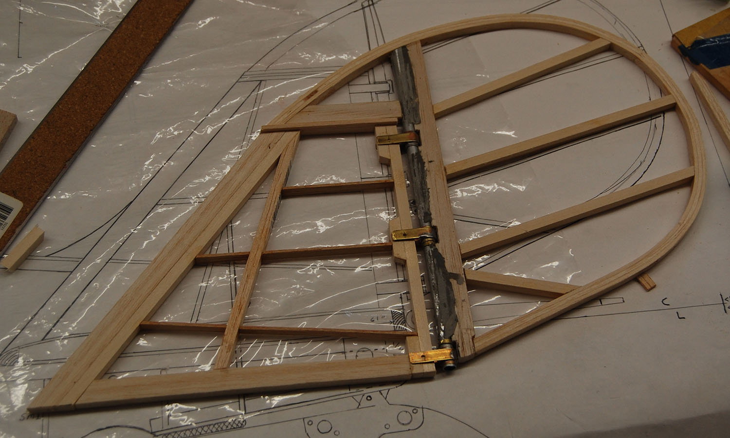
To get my toe wet I started with building the rudder. It has a laminated outline with an aluminium tube and I soldered up a set of brass hinges.
To get my toe wet I started with building the rudder. It has a laminated outline with an aluminium tube and I soldered up a set of brass hinges.

 01-08-2018, 09:38 AM
#4
Back in the Bad Old Days there was a Pfalz D-IIIa plan and construction article published in the June 1971 issue of Flying Models Magazine (plan no.223, by A. Spievak).
Although it was only 1/6 scale, you might find some useful info there.
There is also a new kit in the works, in 1/3 scale. Check here: http://www.rcuniverse.com/forum/rc-s...-offering.html.
Again, that may provide some useful information.
Although it was only 1/6 scale, you might find some useful info there.
There is also a new kit in the works, in 1/3 scale. Check here: http://www.rcuniverse.com/forum/rc-s...-offering.html.
Again, that may provide some useful information.
01-08-2018, 11:26 AM
#5
Thread Starter
Back in the Bad Old Days there was a Pfalz D-IIIa plan and construction article published in the June 1971 issue of Flying Models Magazine (plan no.223, by A. Spievak).
Although it was only 1/6 scale, you might find some useful info there.
There is also a new kit in the works, in 1/3 scale. Check here: http://www.rcuniverse.com/forum/rc-s...-offering.html.
Again, that may provide some useful information.
Although it was only 1/6 scale, you might find some useful info there.
There is also a new kit in the works, in 1/3 scale. Check here: http://www.rcuniverse.com/forum/rc-s...-offering.html.
Again, that may provide some useful information.
01-08-2018, 11:35 AM
#6
Thread Starter
One of the skills I am building is learning to use a CAD program. I used A9cad to generate the former outlines but ended up adding some of the notches and lofting the stringer lines by hand when the selection/cut and paste functions were being cranky. At any rate I've gotten started with the bottom half of the fuselage.
01-08-2018, 09:52 PM
#7
Thread Starter
Moving a little farther along I have installed some of the formers and stringers. In the second picture you can see the ply box that will tie the engine box to the lower wing mount and the landing gear. The third photo shows where the upper anchor will be for the tail skid bungees will go.
01-10-2018, 08:33 PM
#8
Thread Starter
I've been throwing down some stringers. I don't have photos yet but I've started planking the bottom and will at least partially plank it before I do anything else with the fuselage to give it a little stiffness.
01-13-2018, 08:20 AM
#9
Thread Starter
Stringers and planking. Planking a fuselage is probably not the most exiting thing to watch but it is rather relaxing to do. It's not the prettiest planking job you will ever see and there is a lot of sanding and filling in my future. It will eventually be covered and painted so as long as it is strong, smooth and not too heavy it will all be good. Lots of steps ahead for the bottom half of the shell including the lower wing roots, the landing gear mounts, the engine box and other internals. It may not show well on the photos but the internal box structure that ties everything together interlocks with the fuselage formers and now has the right angle joints reinforced with triangle stock. The two slits that can be seen at the tail mark the location where the bungie for tail skid will exit the fuselage.
01-15-2018, 03:03 PM
#11
Thread Starter
01-18-2018, 07:27 PM
#12
Thread Starter
I've added the wing root stubs to the lower fuselage.These are spar carrythroughs that will mount the root ribs. The aft stub will also tie to the rear landing gear mounts. There are gussets to be added yet but these structures serve to tie the lower wing to the engine box structure.This box structure ties together the engine box with the formers that carry the upper cabane mounts and the front landing gear mounts.
01-18-2018, 07:31 PM
#13
Thread Starter
Just a few shots of the engine box. The engine box is made of 1/8th ply and the design is basically lifted from the Top-Flite giant scale P-47. The triangle stock on the box is bass wood while the rest of the triangle stock tying the structure together is balsa.
Last edited by mgnostic; 01-18-2018 at 07:35 PM.
01-24-2018, 08:07 AM
#14
Thread Starter
I am shifting over to tail surfaces for a bit.The reason being that the Pfalz pretty much has to have pull-pull on the control surfaces to look right. I suppose one could do push rods but a 4-40 rod to the rudder would look pretty clunky. By setting up the tail surface I can settle on the paths for the cables. I will also be cutting away at least part of the formers in the aft fuselage to make room and save a little weight. The fuselage is a fairly deep oval especially through the cockpit area and I am going to set up a walking beam for the elevator cables under the seat. I tried laminating a curved leading edge for the stabilizer but it didn't work out. I think the problem was a combination of using too thick wood and not soaking it in water/ammonia long enough. At any rate I didn't produce parts that matched each other or the drawing. I could probably take another shot with a more rigid form and thinner laminations but I will probably just go with horizontal laminations rather than vertical. I also have a wing tube on order for the lower wing.
01-24-2018, 07:11 PM
#15
Thread Starter
Fuel tank porn and the beginnings of a stabilizer. My fuel tank from TaildraggerRC came in and I'm very impressed. A little spendy but it has anodized aluminum hardware and seem like it will be very durable. I have also gotten started on the elevator. I'm pleased with it so far as it is very rigid.I still have to add the control horns and some diagonals as well as do some sanding. Interestingly hinge points will be close to scale. The Pfalz had a built up wooden elevator as opposed to the welded steel rudder and the elevators on the Albatross and Fokker fighters.
01-26-2018, 06:37 PM
#16
Thread Starter
Well, I have been happy with the progress on the build to date but there is going to be a hiatus for a few days at least. After several days of trying to trap the dadburned critter, I finally had to kill a skunk that had taken up residence in my shop building. The level of stink is nothing short of amazing. I didn't get sprayed but after bagging up and removing the skunk I still had to throw away the clothes that I was wearing. Until you have dealt with skunk spray in an enclosed area you really can't imagine the foulness. Luckily he wasn't in the hobby room but you still can't enter the building without a respirator.
02-05-2018, 09:05 PM
#17
Thread Starter
Well the air in the shop has cleared out enough to get back into the hobby room. Or maybe I've just gotten used to the smell  . I have started framing up a stabilizer. I started out building a laminated leading edge for the stabilizer but the two halves didn't come out the same. Even though I soaked everything in ammonia and water, one of the leading edges didn't take the proper curve. I think the problem was that I should have used thinner material for the laminations. I could have ponied up and made a form out of plywood but I took the easier route instead and made the LE out of sheet balsa. I think this will be sufficiently strong but if one had a concern it seems like the laminated LE would be very strong. Once I can mock up the horizontal tail to the fuselage I can start installing the formers for the upper half of the fuselage and the vertical tail. With all of that in place I can lay out the cable runs. As it looks now I should be able to install the cables in a straight shot with minimal need for fairleads except for where the cables exit the fuselage.
If you are interested in building a Pfalz you should take a look at Vogel605's product. It looks like he is gearing for for a very nice kit.
. I have started framing up a stabilizer. I started out building a laminated leading edge for the stabilizer but the two halves didn't come out the same. Even though I soaked everything in ammonia and water, one of the leading edges didn't take the proper curve. I think the problem was that I should have used thinner material for the laminations. I could have ponied up and made a form out of plywood but I took the easier route instead and made the LE out of sheet balsa. I think this will be sufficiently strong but if one had a concern it seems like the laminated LE would be very strong. Once I can mock up the horizontal tail to the fuselage I can start installing the formers for the upper half of the fuselage and the vertical tail. With all of that in place I can lay out the cable runs. As it looks now I should be able to install the cables in a straight shot with minimal need for fairleads except for where the cables exit the fuselage.If you are interested in building a Pfalz you should take a look at Vogel605's product. It looks like he is gearing for for a very nice kit.
03-04-2018, 11:06 AM
#18
Thread Starter
I'm going to be getting back to the Pfalz shortly. Once I get the root of the stabilizer done and the fin in place I can start with the upper half formers, running the pull-pull lines and sheeting the upper half of the fuselage. A question on my mind at the moment is the texture of the fuselage. As I understand it, the wicklerumpf fuselage was covered with a layer of fabric that was doped to the silbergrau color. There are a few exceptions where the laminations appear to show through the fabric, but for the most part the fuselage appears to have a smooth surface. Factory fresh aircraft look to have a little bit of gloss but most photos seem to show a sheen rather than a gloss. There are other aircraft where the paint, particularly the markings, appears to have at least some gloss. My understanding is that some of the gloss is impacted by the weathering of the aircraft.
To what degree was the weave of the fabric filled in when the aircraft was initially painted?
At present I'm thinking about covering the fuselage with a layer of Koverall to give the texture. Any thoughts?
Another area that I want to get right is the joint between the left and right fuselage shells. This doesn't show up all that well in most of my reference materials but it generally appears to be smooth with no obvious seam.
03-06-2018, 03:04 PM
#19


Join Date: Dec 2006
Location: Leawood, KS
Posts: 53
Likes: 0
Received 0 Likes
on
0 Posts
Matt,
Keep up the good work. I think you are doing a great job. This is my second favorite WWI aircraft (after the Albatros). I was actually thinking about scratching one myself at some point. And I like your design objectives - practical but very scale like.
Rob
Keep up the good work. I think you are doing a great job. This is my second favorite WWI aircraft (after the Albatros). I was actually thinking about scratching one myself at some point. And I like your design objectives - practical but very scale like.
Rob
03-07-2018, 08:32 AM
#20
Thread Starter
Rob,Thanks for the comment. I'm trying to keep the profile as scale as possible. Most scale buffs are aware of the limitations of most of the existing Pfalz DIIIa drawings. With this particular airplane I'm trying to strike a balance between creating a recognizable scale model and one that is reasonably convenient to fly. I have seen comments by those who note that they don't fly an airplane very often because of the time required for set up and tear down. I have a of of admiration for those people who make sure they have the correct turnbuckle and the ball and sockets joints are just so. I hope to do one of those airplanes some day but right now having an airplane that I will actually fly is a priority. It's not for everybody but I am finding the scratch build rewarding.
03-22-2018, 07:53 AM
#21
Thread Starter
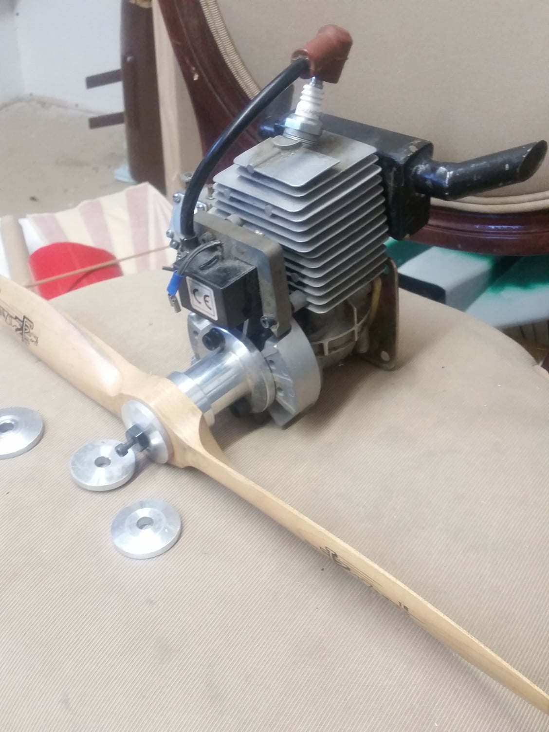
Well it was a two hour drive to the WAMS swap meet in Weatherford, Tx but it was worth it. I scored a pair of G-38s along with a pair of aftermarket mufflers for each engine. The engines have close to sequential serial numbers and may have been intended for one of the twin engine projects that were also for sale at the same table. Now I can finish with mounting the engine box and setting up thrust angles with the firewall is out in the open and easy to get to.
04-26-2018, 08:51 PM
#22
Thread Starter
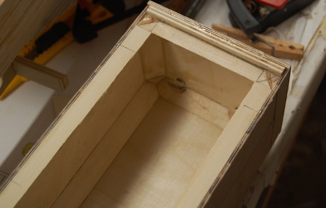
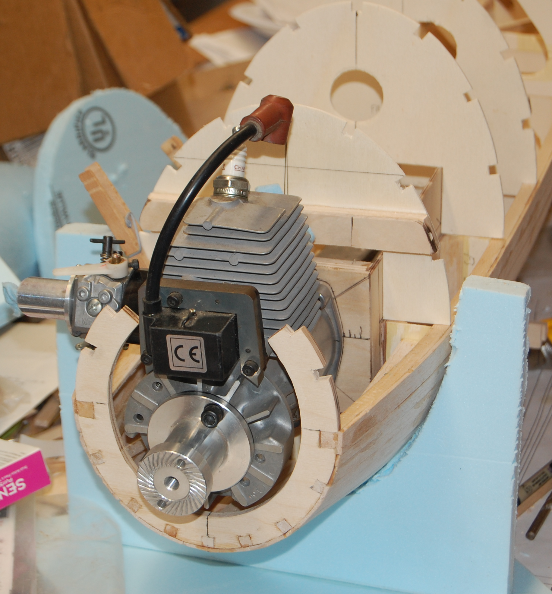
It's been a busy month but I'm getting back to the Pfalz. I made a blue foam cradle for the fuselage to sit in and then got to work on the engine box. The first photo shows the box with some of the triangle stock inside. The second photo shows the G-38 hanging off of the firewall for the purpose of getting the fore and aft location of the box determined. I wanted to get the front of the prop hub 2&3/16ths inches ahead of the face of the F1 former. The engine mount bolts weren't snugged up in the photo so the engine isn't centered in the opening in F1. As can be seen, the Pfalz has a slender pointy nose and fat engines need not apply. It's convenient that the G-38 has a rear exhaust and an engine that also had a rear intake would be even better. As it is I'm fortunate that the carb will at least be partly hidden by the scale exhaust. I may try to go with a smaller intake stack and carb spacer. Electronic ignition would probably make installation easier. Currently it looks like I will have to remove the flywheel and carb for the final installation of the engine and put them back on once the engine is in place. It would be nice if I can whip up a small canister muffler that has an exhaust pipe near the scale location.
04-26-2018, 09:10 PM
#23
Thread Starter
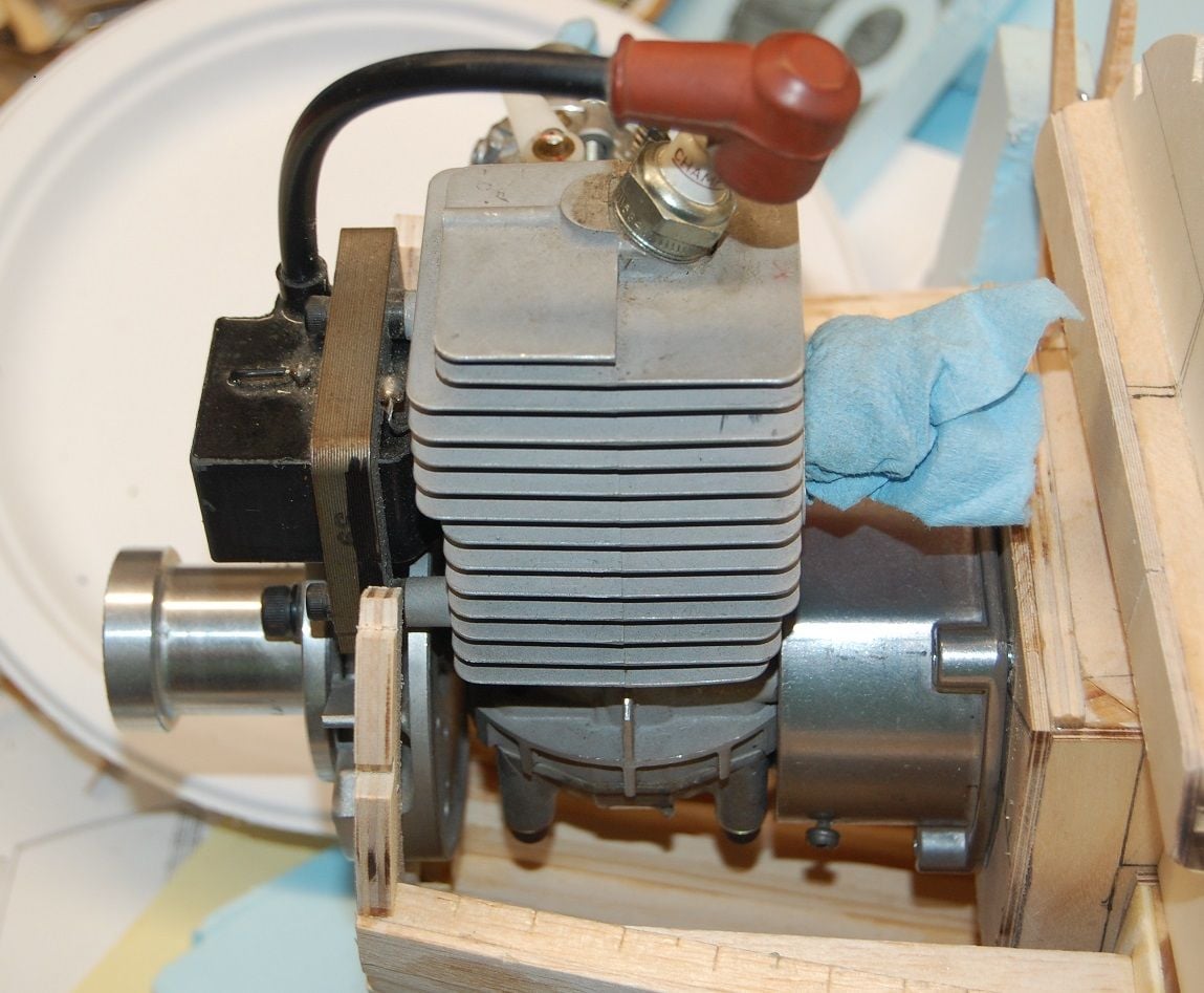
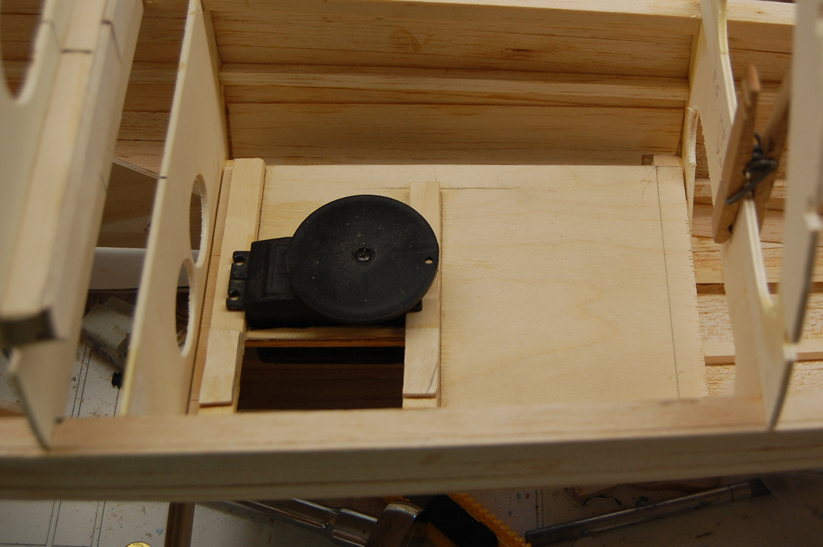
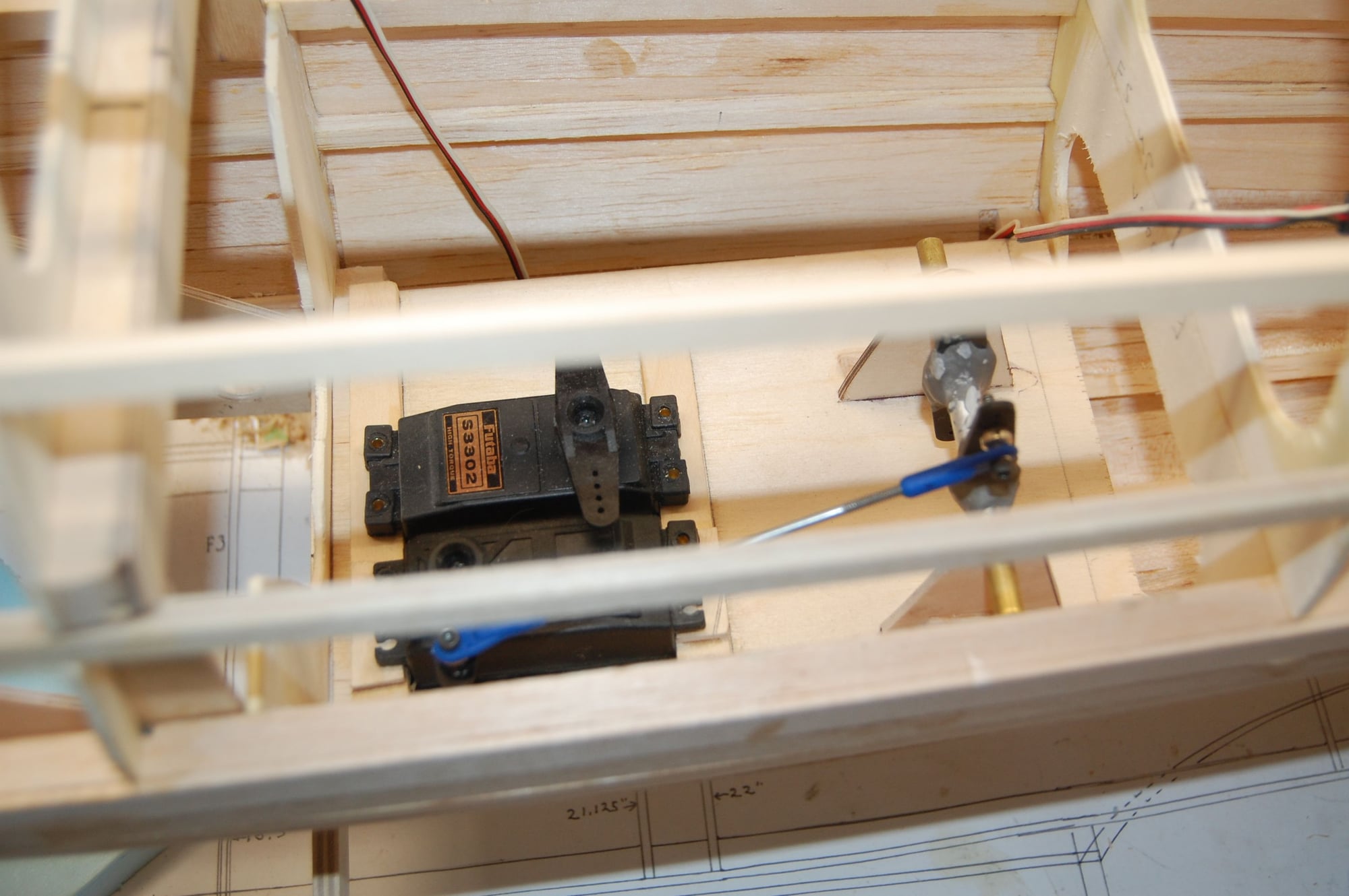
Here are a couple more photos from today. The first just shows the relative position of the engine and firewall and the second shows where the rudder and elevator servos will mount. That is the rudder servo in place and i still need to build a walking beam for the pull pull controls for the elevator. Right now I'm planning on putting the battery up front in the engine box along with the fuel tank. The primary receiver will probably mount on the plate along side of the servos.
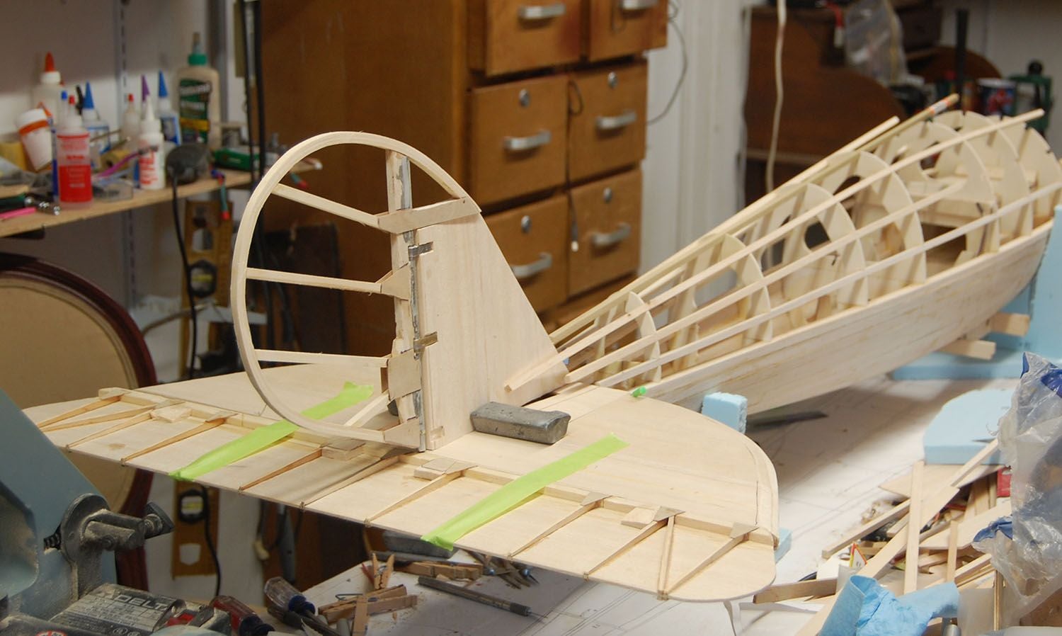
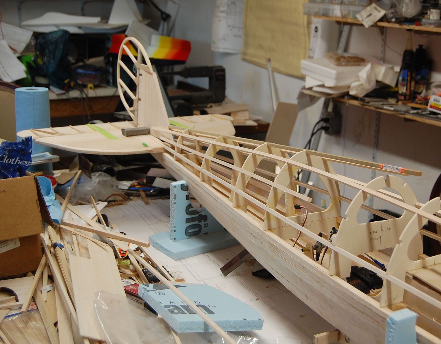
Here is a third photo showing the horizontal stabilizer in progress. In the original design of the Pfalz DIII a the root of the stabilizer is integral to the fuselage. I have since seen images on one of the WWI forums that show a spanwise taper on the stabilizer but I'm pretty much wedded to this one for this model. The structure of the fin is integral to the fuselage and passes through the root of the stabilizer. I'll need to get this in place in order to be able to temporarily install the rudder and elevator and set up the control cables and their exits through the fuselage. With the elevator in place it really has quite the whale tail.
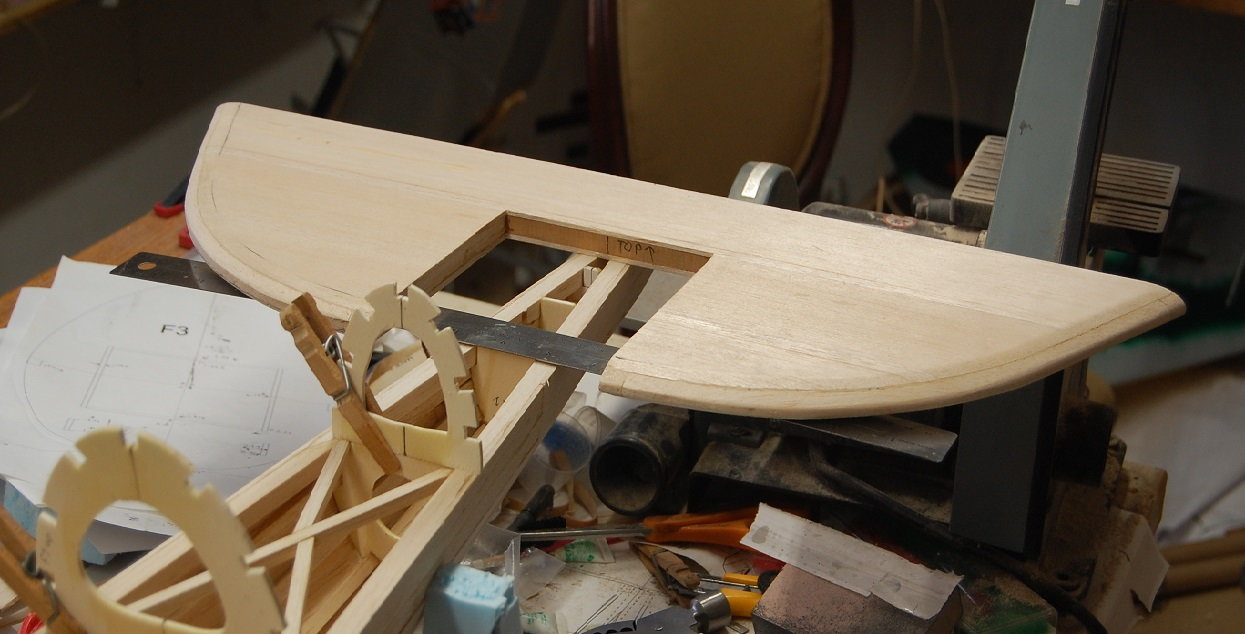
Here is a third photo showing the horizontal stabilizer in progress. In the original design of the Pfalz DIII a the root of the stabilizer is integral to the fuselage. I have since seen images on one of the WWI forums that show a spanwise taper on the stabilizer but I'm pretty much wedded to this one for this model. The structure of the fin is integral to the fuselage and passes through the root of the stabilizer. I'll need to get this in place in order to be able to temporarily install the rudder and elevator and set up the control cables and their exits through the fuselage. With the elevator in place it really has quite the whale tail.
05-02-2018, 08:08 PM
#24
Thread Starter
Some tangible progress has been made. I whipped together the center section of the stabilizer and the fin. In the full scale aircraft the stabilizer center section and the fin are integral to the fuselage. It is necessary to get the fin and center section onto the fuselage so that I can mount the rest of the stabilizer and the elevator and rudder. Once this is all mounted up then I can run the control cables. The walking beam for the elevator and the rudder servo will bring the cables out at a location that should be close to scale. I will get a better picture of the servo mount and walking beam assembly. Right now the fin, stabilizer and servo mounts aren't glued in. I just wanted to get a feel for how they will set. I still have work to do lightening up some of the parts, especially the stabilizer.
I'll add the rest of the photos in subsequent posts.
I'll add the rest of the photos in subsequent posts.
05-02-2018, 08:14 PM
#25
Thread Starter
I have been working with some new photo editing software and was expecting the photos to be considerably smaller. Here are the rest of the photos for the post above.
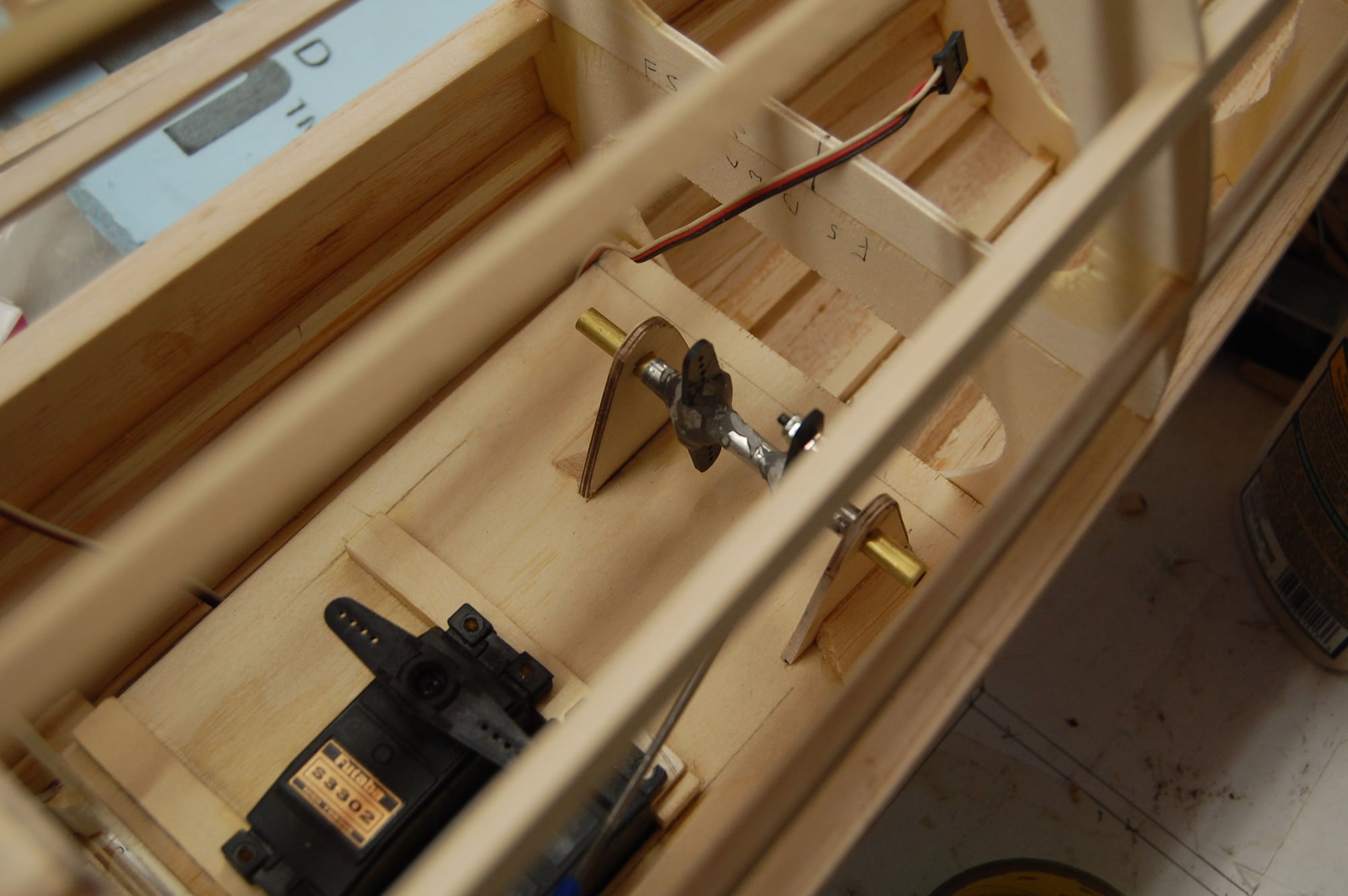
I should note that I may have to raise to servo to get the rudder bar into a good position.
I should note that I may have to raise to servo to get the rudder bar into a good position.