


1/4 Scale Pfalz DIIIa
 11-21-2019, 09:44 PM
#76

Thread Starter

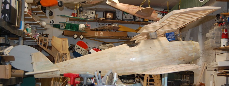
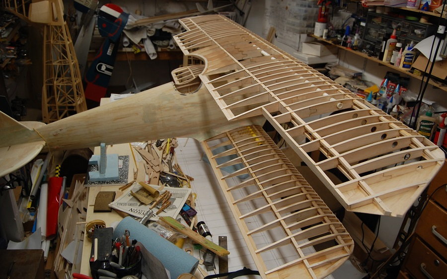
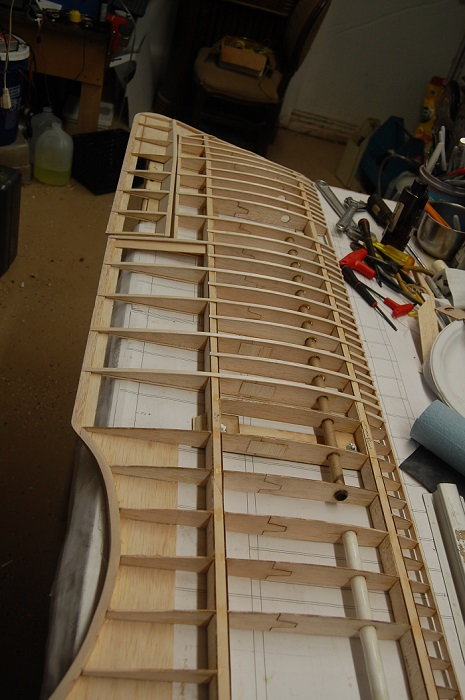
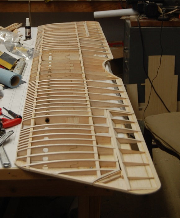
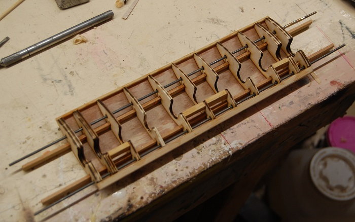
Well, I've made some actual progress on assembling the port lower wing.
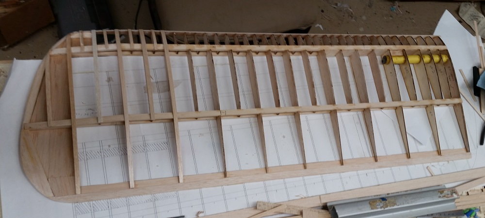
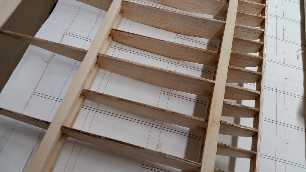
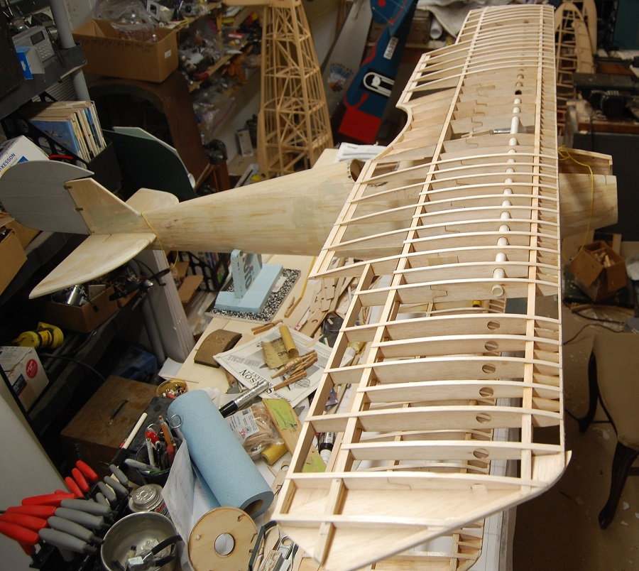
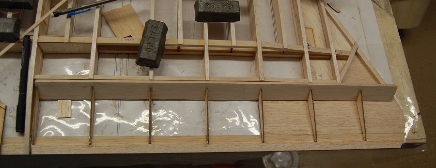
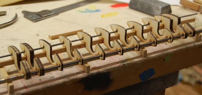
This is a little better photo. I've got the ribs glued n along with the trailing edge and the sub-leading edge. I've done a few cap strips and started in on the shear webs. By the time I add all of the shear webs i will have cut an awful lot of little rectangles. There are about a gazillion of those little nose ribs. While this will eventually be a sport scale style airplane having the ribs adds to the impression of scale. Most of the drawings that you will see don't show the little nose ribs. Most of the drawings out there seem to be based on the DIII not the DIIIa. I have seen photographic evidence that the DIIIa has the little nose ribs. On the full scale aircraft these really aren't even actual ribs. On the full scale Pfalz the nose ribs and half length ribs are just floating cap strips attached to the upper surface of the wing. On the whole, if you have built a BUSA 1/4 scale WWI airplane the wing design should look pretty familiar.
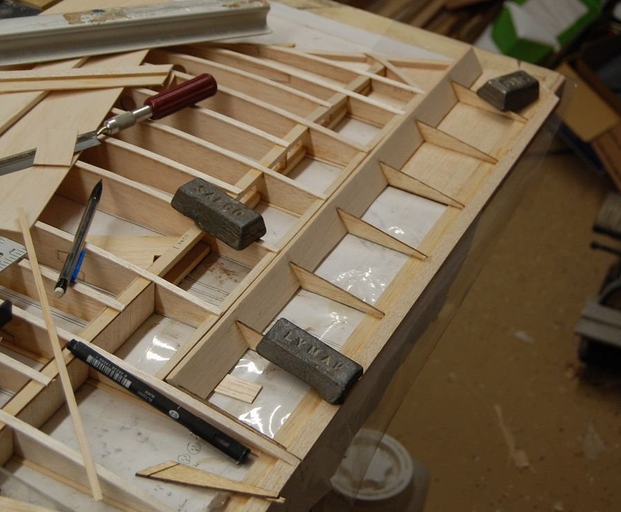
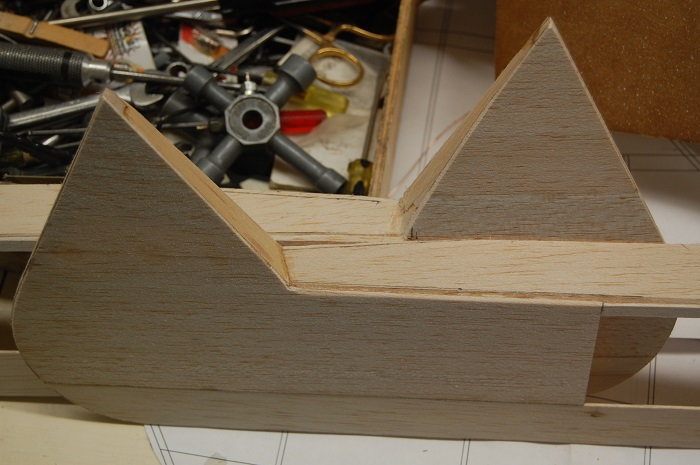
Here is the wing tip. I cut the shape of the tip out of some 1/16 sheet to give the shape and then filled out the edges with some 1/4 inch stock. While not super scale it will resist the tension of the Koverall that I am planning to use for covering. I think it would have a more scale appearance if I had started to thin the wing one rib bay farther in. If i ever do another one, I will do a scale airfoil on the wing but most likely I will just apply the lessons learned on this plane to the next one.
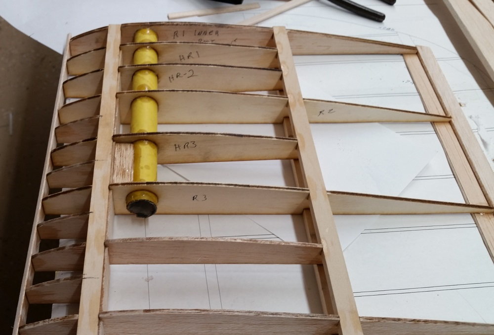
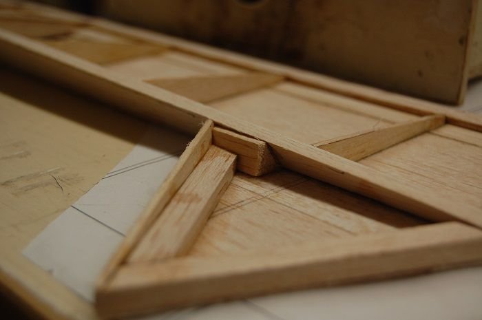
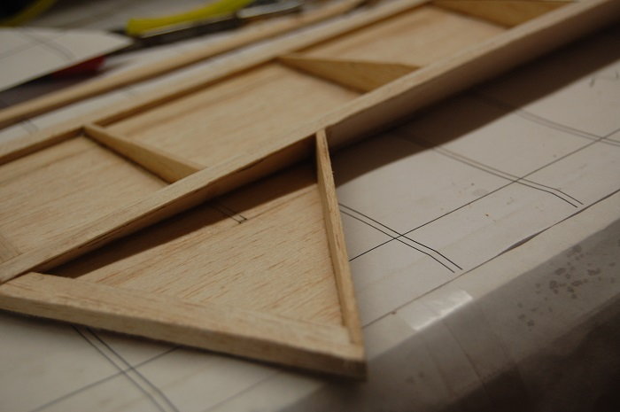
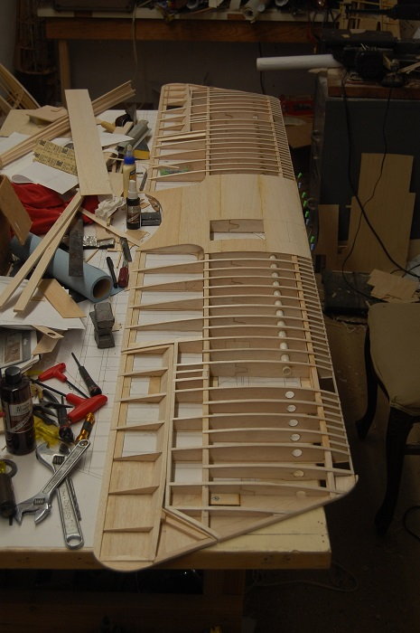
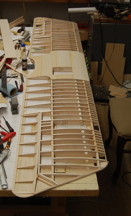
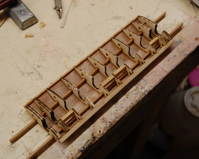
Here is a view looking to the wing root. After mocking up the wing i went back and cut the first three ribs and three half ribs from lite ply rather than balsa. I had to apply a little geometry to calculate the vertical spacing on the holes for the wing tube to pass through but I'm really happy that I got a snug fit on the tube without having to tweak the ribs. The gusset from the wing tube to the spar is visible here as is the beginnings of what will eventually be many pieces of shear web.
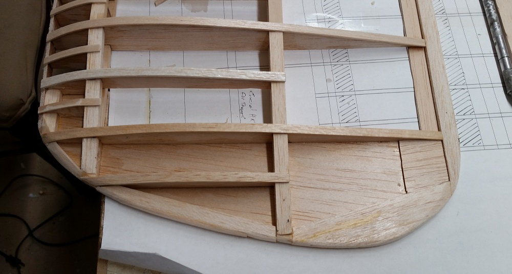
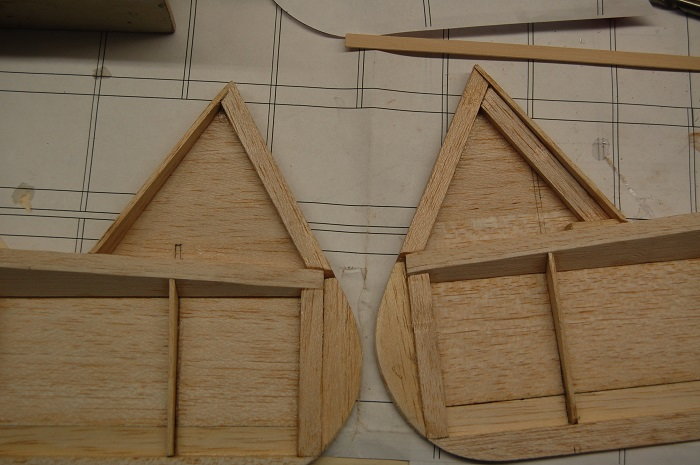
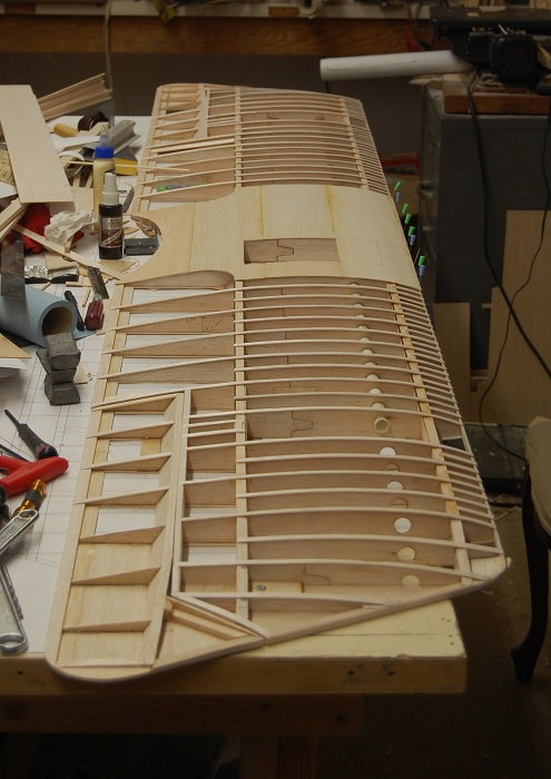
Here is a view of the bottom of the wing. The most notable thing here is that it can be seen that the half ribs don't extend to the bottom surface of the wing. There wasn't a half rib on the bottom of the wing on the full size aircraft so I didn't want that rib shape coming through. The full length ribs will be the only ones cap striped on the bottom so the short nose ribs won't be so obvious.
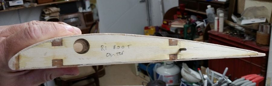
This is another shot of the wing root. In particular you can see that the root rib is laminated from a piece of balsa and a piece of lite-ply. The balsa rib is cut so that it fits over the wing tube while the ply rib is cut to fit the aluminium inner mounting tube. Part of the wing root will be sheeted as per scale but there was no sheeting aft of the rear spar and a stiffener will be added to keep the rib from distorting when the covering is tightened.
There is a lot more to do to the wing in addition to the shear webs and cap strips. There will be an anti-rotation pin in the wing root and hard points for anchoring the wing to the fuselage. It also need mounting points for the wing struts. Although the wing is intended to be strong enough to fly without the scale wing wires there will be hard points for functional bracing to use as desired.
This is a little better photo. I've got the ribs glued n along with the trailing edge and the sub-leading edge. I've done a few cap strips and started in on the shear webs. By the time I add all of the shear webs i will have cut an awful lot of little rectangles. There are about a gazillion of those little nose ribs. While this will eventually be a sport scale style airplane having the ribs adds to the impression of scale. Most of the drawings that you will see don't show the little nose ribs. Most of the drawings out there seem to be based on the DIII not the DIIIa. I have seen photographic evidence that the DIIIa has the little nose ribs. On the full scale aircraft these really aren't even actual ribs. On the full scale Pfalz the nose ribs and half length ribs are just floating cap strips attached to the upper surface of the wing. On the whole, if you have built a BUSA 1/4 scale WWI airplane the wing design should look pretty familiar.
Here is the wing tip. I cut the shape of the tip out of some 1/16 sheet to give the shape and then filled out the edges with some 1/4 inch stock. While not super scale it will resist the tension of the Koverall that I am planning to use for covering. I think it would have a more scale appearance if I had started to thin the wing one rib bay farther in. If i ever do another one, I will do a scale airfoil on the wing but most likely I will just apply the lessons learned on this plane to the next one.
Here is a view looking to the wing root. After mocking up the wing i went back and cut the first three ribs and three half ribs from lite ply rather than balsa. I had to apply a little geometry to calculate the vertical spacing on the holes for the wing tube to pass through but I'm really happy that I got a snug fit on the tube without having to tweak the ribs. The gusset from the wing tube to the spar is visible here as is the beginnings of what will eventually be many pieces of shear web.
Here is a view of the bottom of the wing. The most notable thing here is that it can be seen that the half ribs don't extend to the bottom surface of the wing. There wasn't a half rib on the bottom of the wing on the full size aircraft so I didn't want that rib shape coming through. The full length ribs will be the only ones cap striped on the bottom so the short nose ribs won't be so obvious.
This is another shot of the wing root. In particular you can see that the root rib is laminated from a piece of balsa and a piece of lite-ply. The balsa rib is cut so that it fits over the wing tube while the ply rib is cut to fit the aluminium inner mounting tube. Part of the wing root will be sheeted as per scale but there was no sheeting aft of the rear spar and a stiffener will be added to keep the rib from distorting when the covering is tightened.
There is a lot more to do to the wing in addition to the shear webs and cap strips. There will be an anti-rotation pin in the wing root and hard points for anchoring the wing to the fuselage. It also need mounting points for the wing struts. Although the wing is intended to be strong enough to fly without the scale wing wires there will be hard points for functional bracing to use as desired.
 01-01-2020, 08:33 PM
#78
Thread Starter
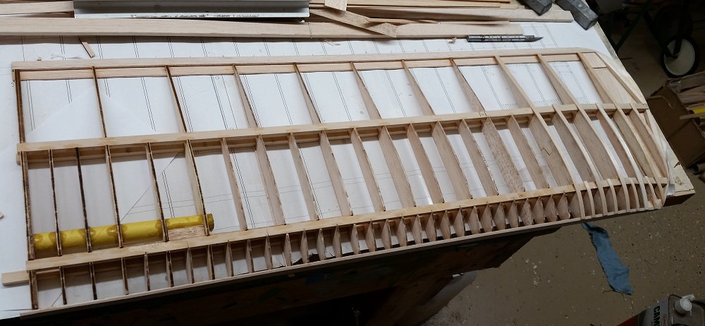
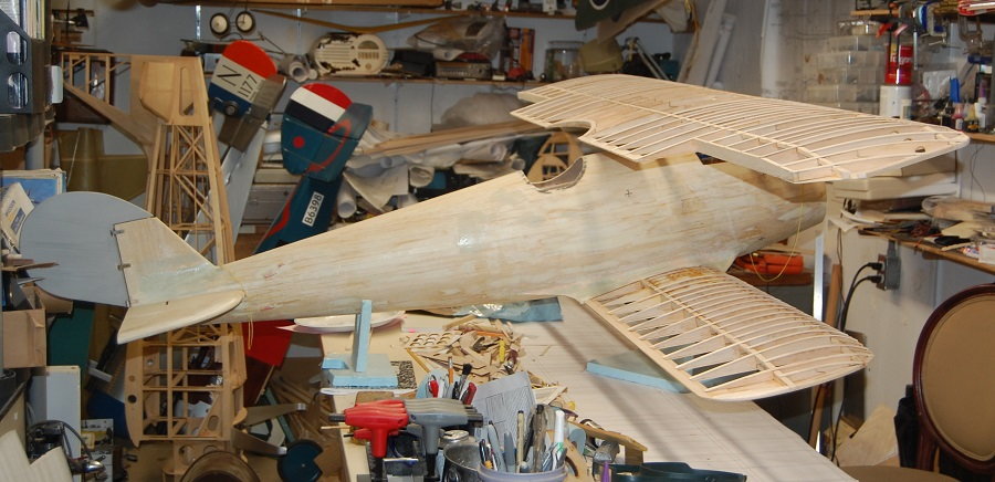
I thought I would celebrate the new year by posting some pictures of progress made. I have to admit to being remiss about keeping up with the thread. On the other hand there isn't a lot that is unique about the wing structure. I think I have mentioned before that the wing structure is basically a BUSA Camel wing blown up to the appropriate chord size with the outline and rib placement rearranged to match the Pfalz. This is the first time that all of the major bits built to date have been in close proximity to one another. The long lens on the camera compresses distance and make the shop look more cluttered than it is but it really is beginning to get a little cluttered. Luckily the Stinson in the background has a home to go to. I'm helping a club member with finishing the framing and installing hardware.
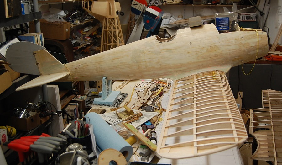
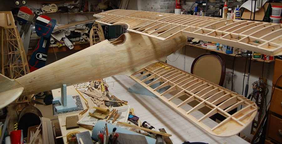
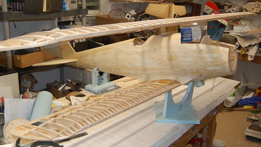
I think I'm approaching the 90% done 90% to go point. The wings need their leading edges and hard points for the struts. Although the airplane should fly without them I am also going to have hard points to mount flying wires. The lower wings will get anti-rotation pins which will also set the angle of incidence. When the time comes I will level the fuselage in the work cradle and mark the datum line. Then I can set the angle of incidence on the lower wings. I'm going to make foam board jigs to hold the upper wing in place while I set up the geometry of the wing struts. Most of the structural data on the full sized aircraft involves the DIII. several were captured and evaluated. A lot of the lack luster performance attributed to the DIIIa is actually based on information from the DIII. The DIIIa was a substantial improvement in the DIII and one of the differences was a decreased angle of incidence on the wings. For modeling reasons I am going to use a modest angle of attack. The goal is to mitigate the tendency to climb at higher throttle settings. Given that the Pfalz has a relatively streamlined structure it may be a little speedier that the rotary engined planes.
I think I'm approaching the 90% done 90% to go point. The wings need their leading edges and hard points for the struts. Although the airplane should fly without them I am also going to have hard points to mount flying wires. The lower wings will get anti-rotation pins which will also set the angle of incidence. When the time comes I will level the fuselage in the work cradle and mark the datum line. Then I can set the angle of incidence on the lower wings. I'm going to make foam board jigs to hold the upper wing in place while I set up the geometry of the wing struts. Most of the structural data on the full sized aircraft involves the DIII. several were captured and evaluated. A lot of the lack luster performance attributed to the DIIIa is actually based on information from the DIII. The DIIIa was a substantial improvement in the DIII and one of the differences was a decreased angle of incidence on the wings. For modeling reasons I am going to use a modest angle of attack. The goal is to mitigate the tendency to climb at higher throttle settings. Given that the Pfalz has a relatively streamlined structure it may be a little speedier that the rotary engined planes.
The following users liked this post:
riv187 (04-10-2020)
04-09-2020, 08:19 AM
#79
Thread Starter
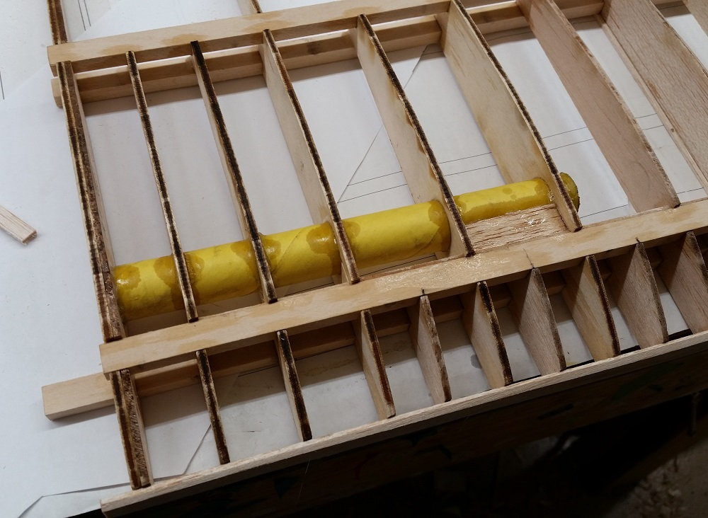
I've been spending a little more time on the Pfalz. Below is a shot of the lower wing root. As I've mentioned before the airfoil and design is the same as some of the BUSA designs, just adjusted t meet my needs. I'm not sure if that will be the final anti rotation pin.
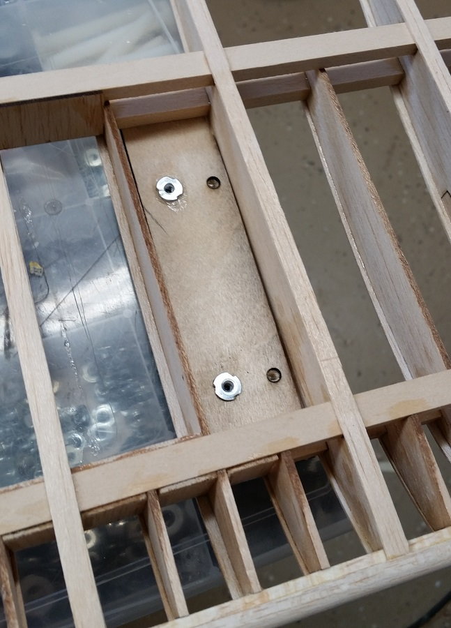
I have mounted a bunch of blind nuts. This is the upper wing center section. I am using 8-32 blind nuts and cap screws. You can see that I leave myself notes on the various parts.

This is a blind nut for the wing tip bracing wire on the upper wing. The D3a had a wire that braced the wing tip. There were at least three variations on where this wire was attached. It isn't necessary to fly the model but i wanted the mounting point for when I want to dress up the model.
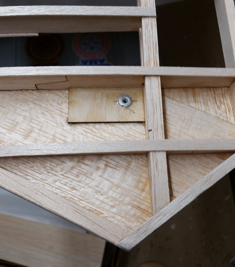
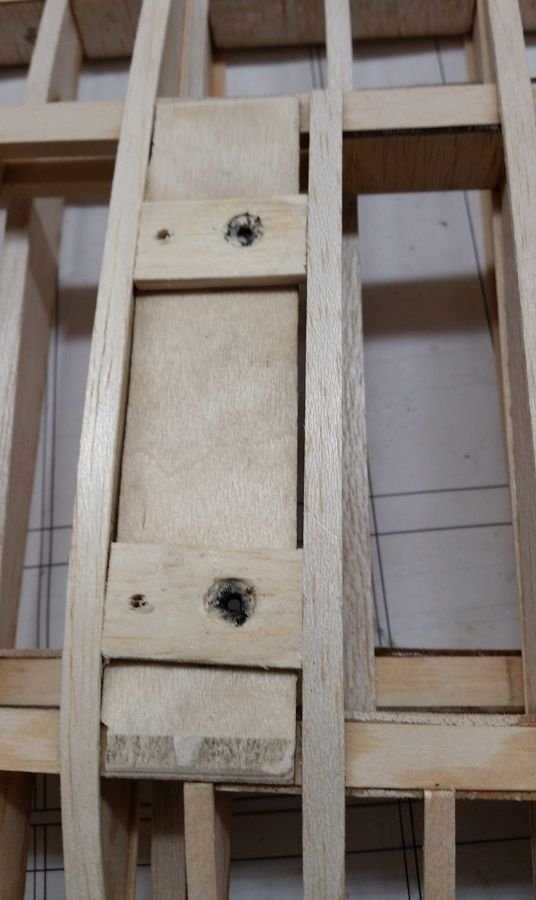
The next three shots show the mounting point for the wing struts on the lower wing. One hole for a strut, one hole to the mounting screw going into a blind nut. The wing struts will have tabs for the optional flying wires.
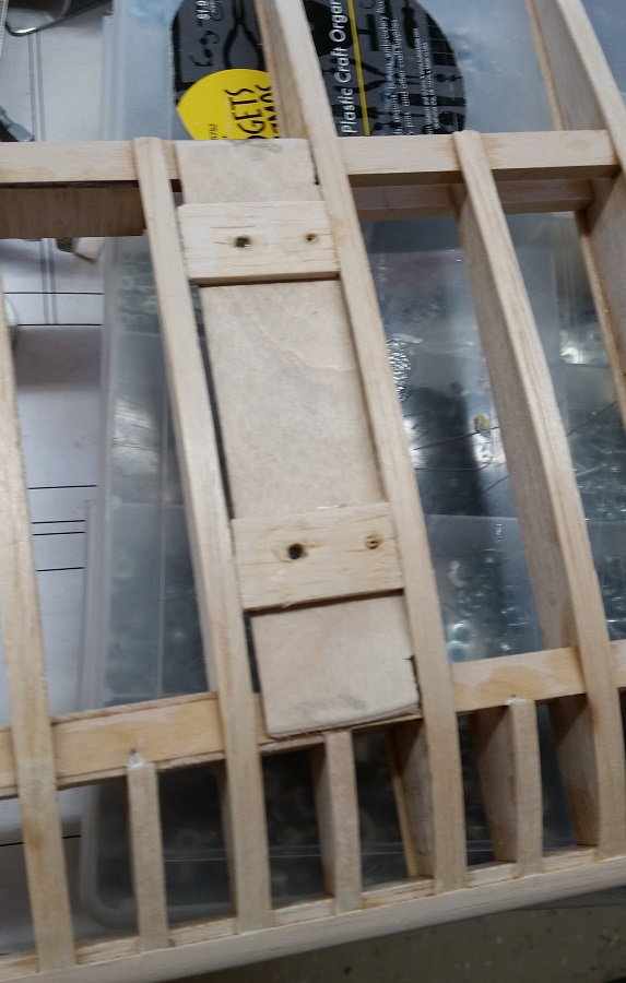
You may notice that some of the sub ribs and nose ribs only have cap strips on one side. That is because they simulate the floating cap strips that only existed on the top side of the wing. As far as i can tell from the photos i have studied they don't seem to have been rib stitched or taped.
I have mounted a bunch of blind nuts. This is the upper wing center section. I am using 8-32 blind nuts and cap screws. You can see that I leave myself notes on the various parts.
This is a blind nut for the wing tip bracing wire on the upper wing. The D3a had a wire that braced the wing tip. There were at least three variations on where this wire was attached. It isn't necessary to fly the model but i wanted the mounting point for when I want to dress up the model.
The next three shots show the mounting point for the wing struts on the lower wing. One hole for a strut, one hole to the mounting screw going into a blind nut. The wing struts will have tabs for the optional flying wires.
You may notice that some of the sub ribs and nose ribs only have cap strips on one side. That is because they simulate the floating cap strips that only existed on the top side of the wing. As far as i can tell from the photos i have studied they don't seem to have been rib stitched or taped.
04-09-2020, 06:39 PM
#80
Thread Starter
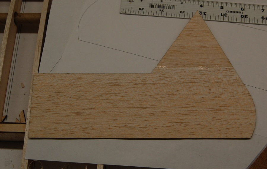
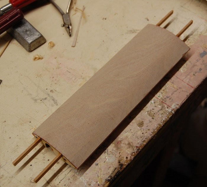
Starting in on some ailerons. To help with the stiffness of the aileron I'm starting off with a 1/16 sheet outline of the tip. The full scale aircraft had quite a bit of plywood sheeting at the tip of the aileron.
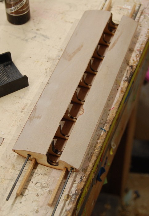
Getting into the construction it can be seen that the aileron ribs are just trimmed from the wing ribs in the aileron bay. These ailerons are a bit of a compromise. The wing on the full scale aircraft is quite a bit thinner at the aileron hinge and it doesn't have the big bevel seen on these ailerons. The model will have the ailerons hinged at the top of the aileron leading edge. This will allow a relatively simple aileron hinge line while keeping the hinge gap tight, at least for most of the span of the aileron. At the tip where the wing tapers in thickness it will be necessary to have the pivot point of one hinge hanging out in the breeze a little bit.
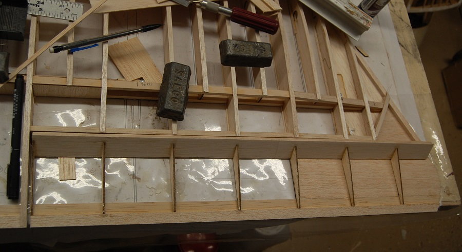
Getting into the construction it can be seen that the aileron ribs are just trimmed from the wing ribs in the aileron bay. These ailerons are a bit of a compromise. The wing on the full scale aircraft is quite a bit thinner at the aileron hinge and it doesn't have the big bevel seen on these ailerons. The model will have the ailerons hinged at the top of the aileron leading edge. This will allow a relatively simple aileron hinge line while keeping the hinge gap tight, at least for most of the span of the aileron. At the tip where the wing tapers in thickness it will be necessary to have the pivot point of one hinge hanging out in the breeze a little bit.
The following users liked this post:
riv187 (04-10-2020)
11-29-2020, 08:27 AM
#81
Thread Starter
As it seems to happen with me, other projects have gotten in the way a bit. I seem to keep three or four irons in the fire most of the time. The Pfalz has been hanging from the workshop ceiling with the lower wings mounted. Every time I have looked at it, it seems the lower wings were not at exactly the same angle of incidence. I finally took it down and propped it up on the bench. This required rearranging a Top Flite Stinson that I have been working on for a buddy of mine that has been a bit of a long term project. I've been fiddling with retractable landing lights and I wasn't satisfied with the outcome of the first iteration. It's time to take a break from that. So down comes the Pfalz. Out comes the incidence gauge and the port wing has about one degree more positive incidence than the starboard wing. A little algebra told me that I needed to move the anti-rotation pin in the wing rood down about 1/16 of an inch. It only takes a second to describe but the actual measuring, checking, filling the old hole for the pin, drilling a new hole for the pin and checking again took about an hour. but it is right now. This is one of those points where learning as you go is kind of frustrating. In between building the fuselage and building the wings I procured one of those inexpensive Chinese laser cutters. As is often noted, getting one of those things to the point of being useful can turn into a hobby itself. Mine isn't ever going to be production capable, but it functions nicely as a precision scroll saw. My CAD skills are limited (see comment about learning as you go) but they are good enough to do the wing ribs and I was particularly pleased with being able to cut the wing ribs with the holes for the wing tube offset the create the desired dihedral angle. Where this relates to the issues of wing incidence is that if I had the laser available when building the fuselage I could have really accurately located a rear wing tube all the way through the core box in the fuselage and out into the wing ribs. In this case an carbon arrow shaft would have done nicely. Oh well, it's knowledge for the next one. If you look back through some of the recent photos you may notice that a number of the wing ribs are jig-sawed together. That is a result of the limited cut area of the laser. As delivered it is set up to cut an area about 6" by 8". I've enlarged the cutting surface to about one square foot. There is room in the case to increase the cutting area by another couple of inches but that will require building another cutting surface.
12-24-2020, 01:34 PM
#82
Thread Starter
Here are some further shots of the aileron. Basically I'm just filing in an aileron shaped space. Admittedly it is not particularly elegant. You can see how the aileron tapers with the wing tip. It will get some cap strips and further sheeting as the wing progresses. The scale aileron horn will also be added in. The full scale aircraft ran the aileron cables through the lower wing and the model will have servos in the upper wing but this is a very visible scale feature. It will be present as part of the aileron structure. One could simulate the aileron cables by running a loop of cable from the ends of the scale horn through a guide in the lower wing.
12-26-2020, 07:34 AM
#83
Thread Starter
The majority of the upper wing structure is done. I'm just now getting around to posting these photos although they were taken a various times through the fall and summer.
Here are some shots with part of the wing sheeting in place and the slots for the aileron horns in place.
Here are some shots with part of the wing sheeting in place and the slots for the aileron horns in place.
01-02-2021, 01:07 PM
#84
Thread Starter
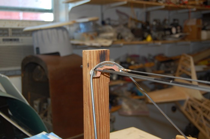
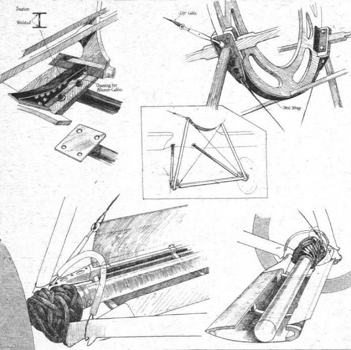
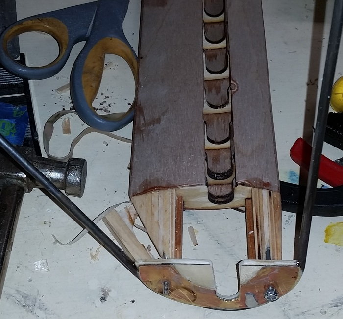
Here are a few photos of the landing gear jig and an illustration from "Flight" magazine from 1918. I'm working on the third iteration of the landing gear. The first was too clunky and the second was way too short. It is well known that the Wylam drawings which are the most commonly seen have errors and in the case of the landing gear just don't have the plan dimensions of the landing gear legs. But in the time since the first effort at landing gear legs I've come across some other drawings in various profile publications and with the assistance various people on the internet. Some of this dated included drawings from a Pfalz factory parts catalogue for the DIII. I was able to locate the axel, the track of the landing gear, the dimensions of spreader bar and the position landing gear mounts with regard to the thrust line and the nose of the airplane. That allowed me to build a jig that located the landing gear leg mounts and the axel so that I could connect the landmarks with landing gear structure. I still have to build the spreader bar structure and the various mounting tabs but at least the gear legs seem to visually line up with the drawings and photos.

There is trimming to do and struts will have to be built up. The wires in front of and behind the axel will support the spreader bar.

The various mounting points are in the same position relative to each other as those on the model.
Here are some details of the spreader bar and mounting points.
There is trimming to do and struts will have to be built up. The wires in front of and behind the axel will support the spreader bar.
The various mounting points are in the same position relative to each other as those on the model.
Here are some details of the spreader bar and mounting points.
01-25-2021, 12:31 PM
#85
Thread Starter
Bit of an image dump but it illustrates the structure of the spreader bar.

Skinned with 1/64 ply.
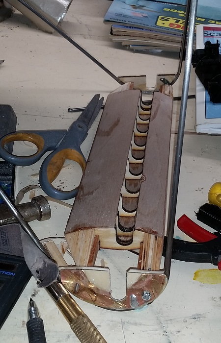
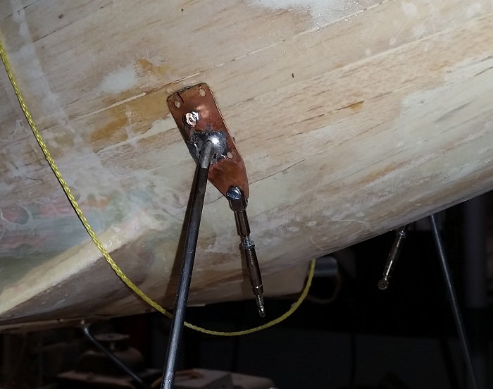
This last photo is the upper mounting plate for the forward gear leg. It has the turnbuckle for the landing gear bracing wire.
Skinned with 1/64 ply.
This last photo is the upper mounting plate for the forward gear leg. It has the turnbuckle for the landing gear bracing wire.
01-26-2021, 08:34 AM
#87
Thread Starter
01-27-2021, 08:49 AM
#89
Thread Starter
There is not a lot of scale action within a hundred miles of me. There are a couple of BUSA 1/3 scale planes in the club at Duncan, Ok but it seems like you have to get down around Dallas/Ft Worth before you see much WWI stuff. The Pfalz may be ready in time for my club's funfly in October. In the mean time I'm enjoying my Sopwith Camel and am planning to make a few events up into Oklahoma this year.
01-21-2022, 08:41 PM
#90
Thread Starter
Well dang, this is just kind of sad. I've left this thread sit for almost exactly a year. Insert excuses about life event, other airplanes, other projects and so on.
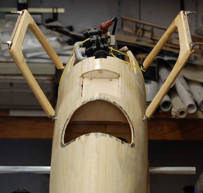
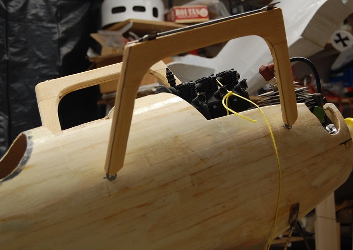
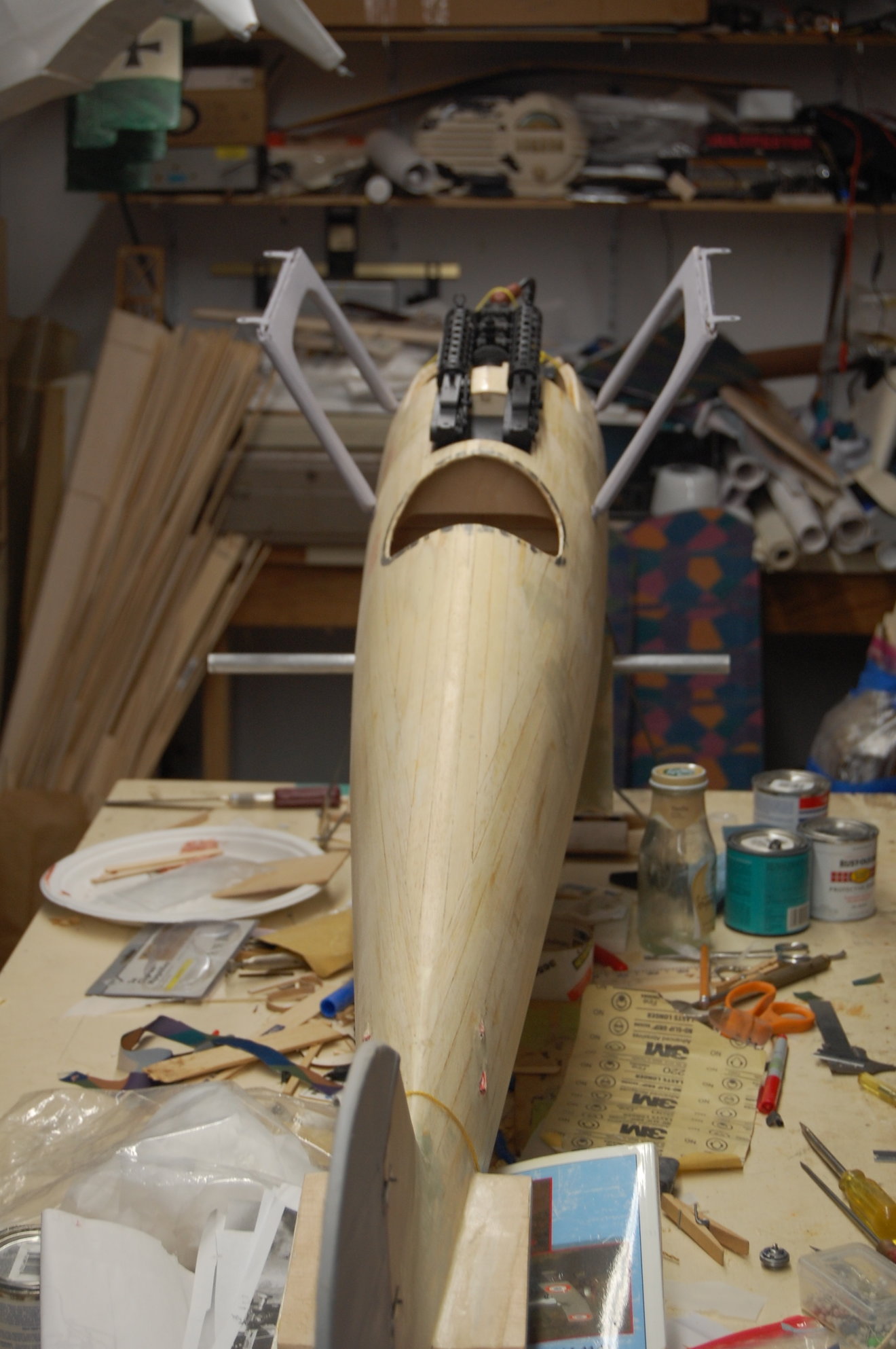
I haven't been completely unproductive. In the photo below you can see the beginnings of a 3-D printed Mercedes, the beginnings of some cabane struts and the hatch where the machine guns will sit.
The cabanes are pretty straight forward. It is just a music wire strut clad in pine and balsa to give a scale shape. There is still some shaping and cleanup to do.
As nearly as I can find out the struts were actually about two inches thick. It seems a little odd when holding the strut but we'll see how it looks when they are painted.
I guess I am going to have to do another post to show the jig I made up for building the wing struts. Another too long between posts problem.
The wing struts are pretty simple and were just built up between the wings after the cabanes were installed. Yeah, they are made from Lowes yardsticks. They were straight, cheap and had a beautiful grain.

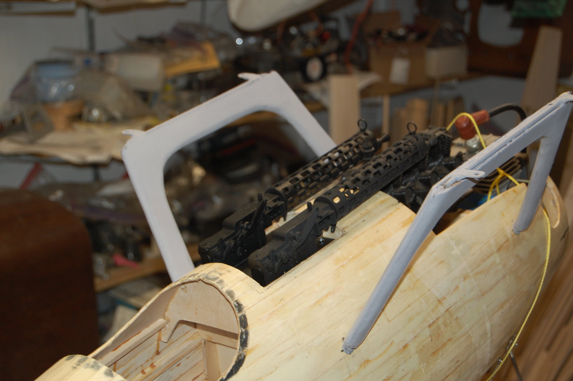
Here is the machine gun hatch. The full scale had a sheet metal frame around the gun installation. I'll make that up after the guns are installed and I make up the ammunition troughs and the ammo belt chutes.
There will also be a small fairing behind the cam gear housing on the engine. So far the engine is just a set of cylinders and intake manifold that i bought off the internet and printed.
I'm not sure how much of the front three cylinders I will get to use as the G-38 takes up a lot of space. If anybody else tries to build a DIIIa I would suggest going with an inverted engine and let the head hang through the bottom of the cowl
or go electric.
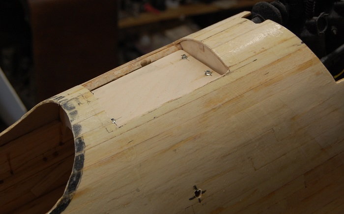
Another view of the gun hatch. The laminated structure in the middle is the carry through for the cabane mounts. There is not much else going on there so I will use it to mount the ammo box.
In the full scale the box hangs down quite a ways and it will be visible when looking into the cockpit.
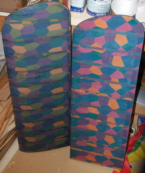
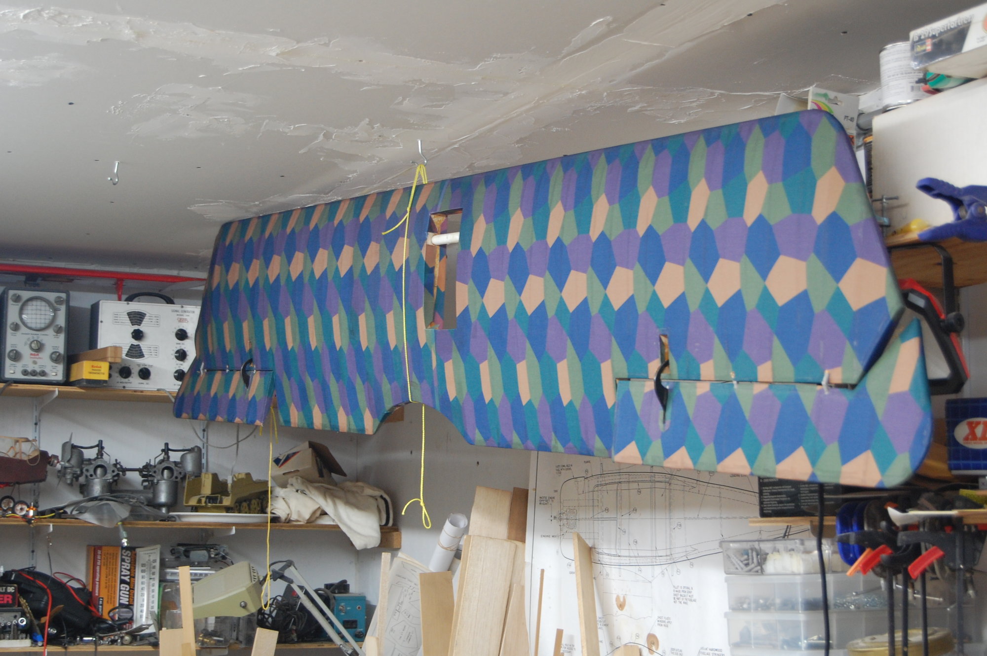
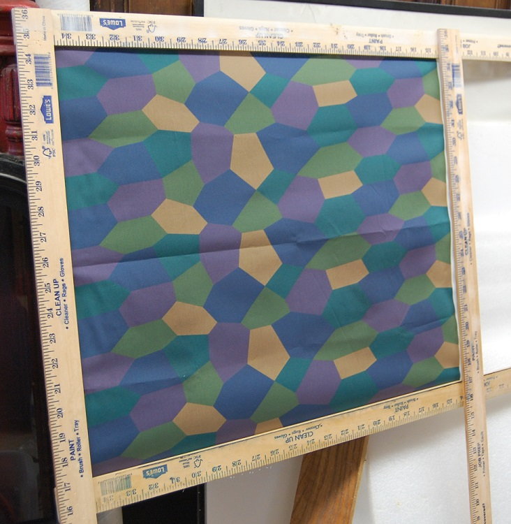
Now we have some color. the lower wings covered in 1/4 scale lozenge fabric from Spoonflower. They aren't perfect but I'm pretty happy.
The fabric doesn't heat shrink so a lot of care has to be used in attaching the fabric. I used Sig Stix-it and then shrunk the fabric with four coats of Randolph Taughtening Nitrate Dope.
I usually use Sig dope but it didn't have enough shrink. I got the Randolph from Aircraft Spruce. Good ventilation is definitely required.
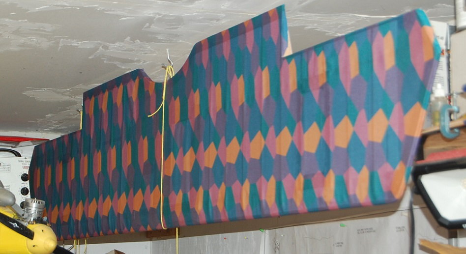
I just started covering the upper wing. This is just after the first coat of 50% strength dope. It has snugged up a bit since this photo.
The dope fumes go to the girls in the covering room and they got one panel a little crooked. I think they had too much schnapps at lunch.
As for the Spoonflower fabric, I can't swear to its accuracy. It's not very forgiving and it is kind of expensive. I would not recommend it for a first covering job.
But...If you just have to have printed lozenge camo, the fabric is pretty neat. It does come in a variety of scales and an upper and lower surface set of colors.
I used silky faille polyester but this fabric is NLA. I'm using the cotton poplin for the rib tapes. Spoonflower is a print to order company and you can select on of a variety of fabrics. Their turnaround time is really quite fast.
I would strongly suggest getting a variety of fabric samples before committing to buying the $100 bucks or so that you will spend covering a 1/4 scale plane. That a $100 in fabric, not including adhesive, dope, thinner and other incidental.
I haven't been completely unproductive. In the photo below you can see the beginnings of a 3-D printed Mercedes, the beginnings of some cabane struts and the hatch where the machine guns will sit.
The cabanes are pretty straight forward. It is just a music wire strut clad in pine and balsa to give a scale shape. There is still some shaping and cleanup to do.
As nearly as I can find out the struts were actually about two inches thick. It seems a little odd when holding the strut but we'll see how it looks when they are painted.
I guess I am going to have to do another post to show the jig I made up for building the wing struts. Another too long between posts problem.
The wing struts are pretty simple and were just built up between the wings after the cabanes were installed. Yeah, they are made from Lowes yardsticks. They were straight, cheap and had a beautiful grain.
Here is the machine gun hatch. The full scale had a sheet metal frame around the gun installation. I'll make that up after the guns are installed and I make up the ammunition troughs and the ammo belt chutes.
There will also be a small fairing behind the cam gear housing on the engine. So far the engine is just a set of cylinders and intake manifold that i bought off the internet and printed.
I'm not sure how much of the front three cylinders I will get to use as the G-38 takes up a lot of space. If anybody else tries to build a DIIIa I would suggest going with an inverted engine and let the head hang through the bottom of the cowl
or go electric.
Another view of the gun hatch. The laminated structure in the middle is the carry through for the cabane mounts. There is not much else going on there so I will use it to mount the ammo box.
In the full scale the box hangs down quite a ways and it will be visible when looking into the cockpit.
Now we have some color. the lower wings covered in 1/4 scale lozenge fabric from Spoonflower. They aren't perfect but I'm pretty happy.
The fabric doesn't heat shrink so a lot of care has to be used in attaching the fabric. I used Sig Stix-it and then shrunk the fabric with four coats of Randolph Taughtening Nitrate Dope.
I usually use Sig dope but it didn't have enough shrink. I got the Randolph from Aircraft Spruce. Good ventilation is definitely required.
I just started covering the upper wing. This is just after the first coat of 50% strength dope. It has snugged up a bit since this photo.
The dope fumes go to the girls in the covering room and they got one panel a little crooked. I think they had too much schnapps at lunch.
As for the Spoonflower fabric, I can't swear to its accuracy. It's not very forgiving and it is kind of expensive. I would not recommend it for a first covering job.
But...If you just have to have printed lozenge camo, the fabric is pretty neat. It does come in a variety of scales and an upper and lower surface set of colors.
I used silky faille polyester but this fabric is NLA. I'm using the cotton poplin for the rib tapes. Spoonflower is a print to order company and you can select on of a variety of fabrics. Their turnaround time is really quite fast.
I would strongly suggest getting a variety of fabric samples before committing to buying the $100 bucks or so that you will spend covering a 1/4 scale plane. That a $100 in fabric, not including adhesive, dope, thinner and other incidental.
The following users liked this post:
riv187 (01-22-2022)
02-02-2022, 03:46 PM
#92
Thread Starter
Getting the guns mounted on to their plate. There are still ammo chutes to make but now you can see how they will sit. I've shaped the wing struts a bit more so they aren't so clunky but there is a lot of sanding in their future.
The tail surfaces have actually been built for a couple of years but i just finished doing some rib tapes. Since starting this build I've since learned that the horizontal tail is a fabric covered structure and not plywood covered as shown in many available drawings. Since this is just a sport model I'm not going to build a new one.
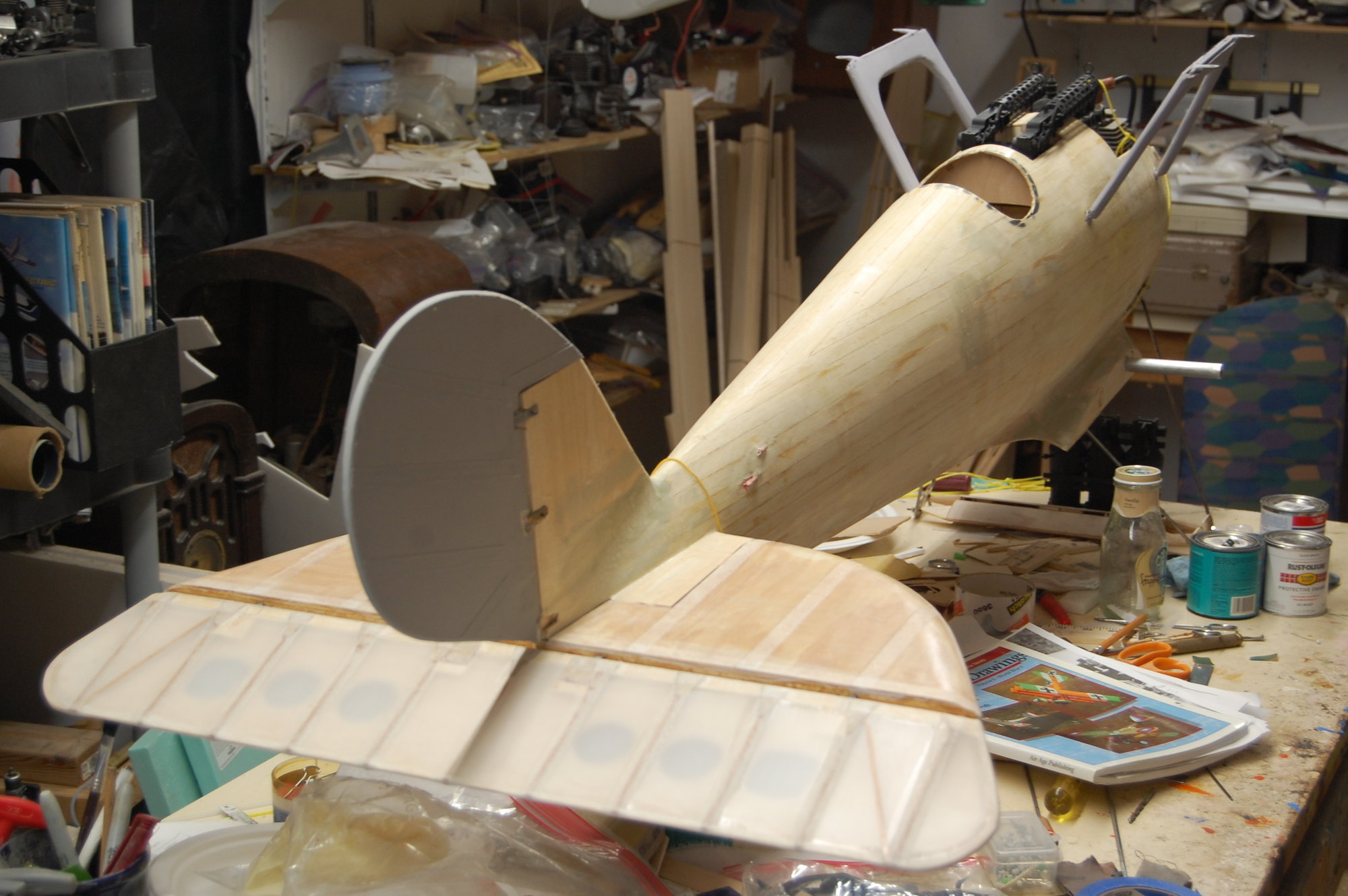
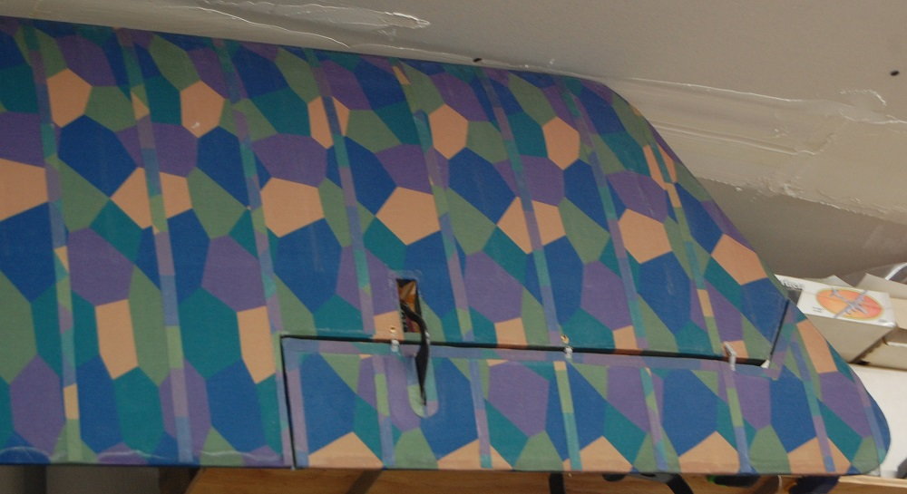
Got the upper surface of the top wing covered and the ailerons are mocked into place. I still have to make the aileron servo mounts and do the rib tapes before the ailerons go on permanently.
And here are some rib tapes.
The tail surfaces have actually been built for a couple of years but i just finished doing some rib tapes. Since starting this build I've since learned that the horizontal tail is a fabric covered structure and not plywood covered as shown in many available drawings. Since this is just a sport model I'm not going to build a new one.
Got the upper surface of the top wing covered and the ailerons are mocked into place. I still have to make the aileron servo mounts and do the rib tapes before the ailerons go on permanently.
And here are some rib tapes.
The following users liked this post:
riv187 (02-02-2022)
 02-04-2022, 05:01 PM
#94
Thread Starter
Thankyou, It has turned into a bit of a long term project.
02-27-2022, 07:43 PM
#95
Thread Starter
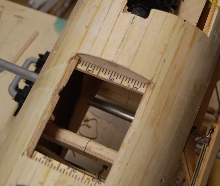
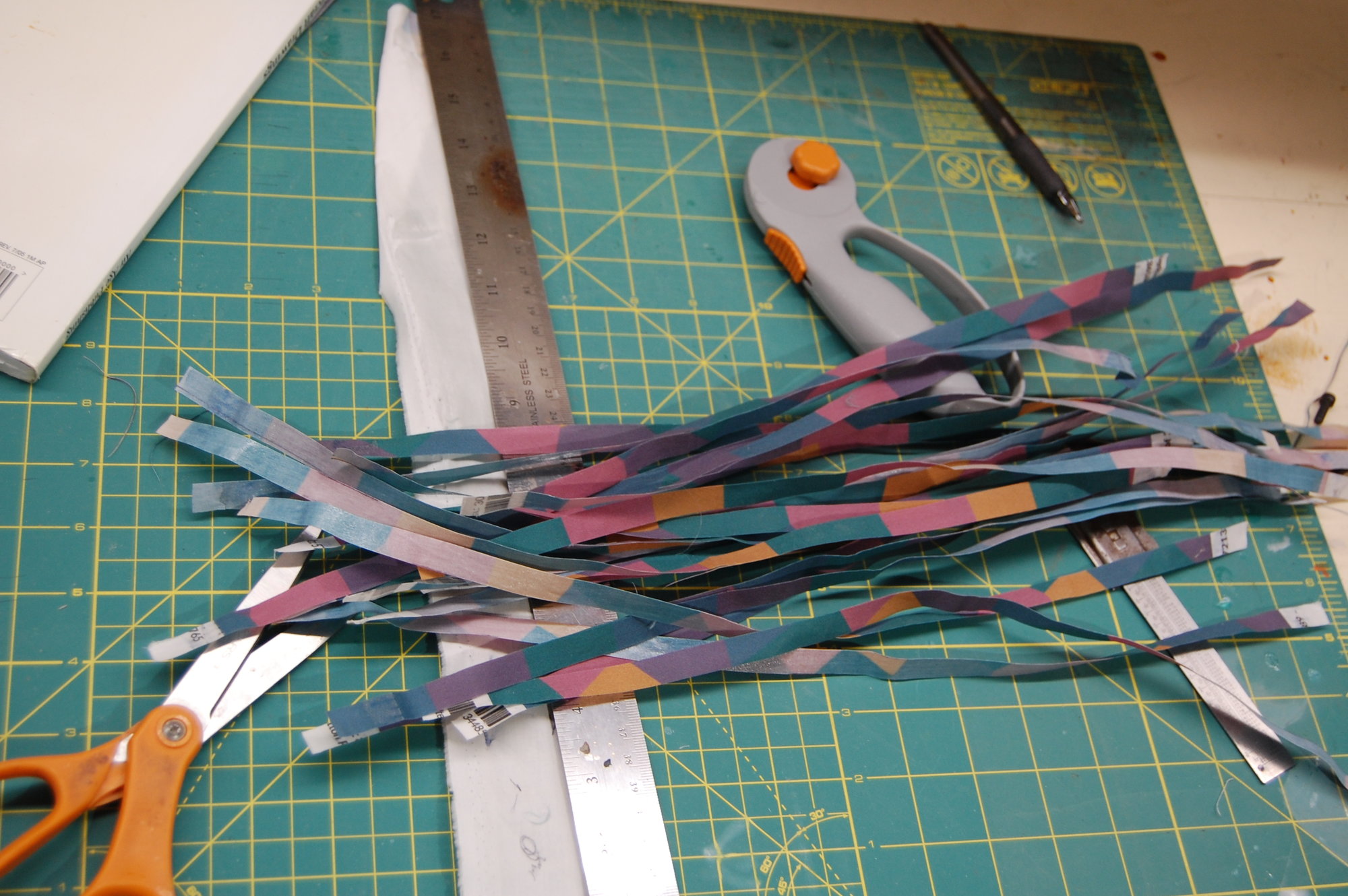
I've been poking at the Pfalz. Below is another chunk of fabric that is being prepped for cutting into rib tapes. It's just easier to hit it with a little bit of dope and then a coat of Stix-it on the back side before slicing it into tapes.
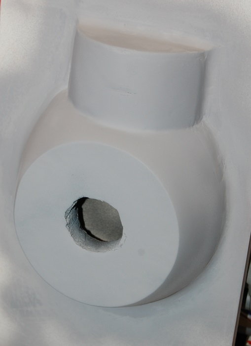
A little more work on the nose bowl. Hopefully this will be a plug for a fiberglass mold. It has potential but it has been too chilly for wet sanding.
Top wing with some tapes on. The big hole is where the radiator will go.
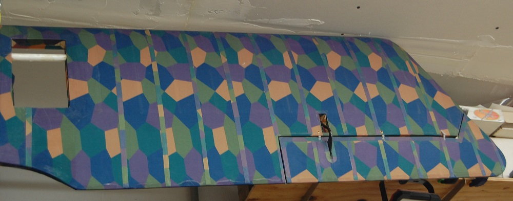
A little closer view of the upper wing. I didn't have enough tapes to finish the wing and had to order more fabric before I could finish.
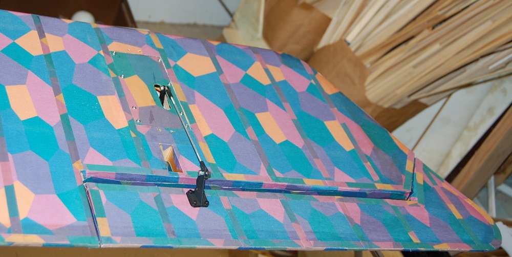
A quick look at the bottom wing with the aileron servo roughed in. WWI airplanes seem to like a lot of differential aileron.
A little more work on the nose bowl. Hopefully this will be a plug for a fiberglass mold. It has potential but it has been too chilly for wet sanding.
Top wing with some tapes on. The big hole is where the radiator will go.
A little closer view of the upper wing. I didn't have enough tapes to finish the wing and had to order more fabric before I could finish.
A quick look at the bottom wing with the aileron servo roughed in. WWI airplanes seem to like a lot of differential aileron.
04-06-2022, 07:20 AM
#97
Thread Starter
Thanks, progress can kind of be hit or miss but it will eventually get finished. The plug for the nose bowl is ready to make a mold. I just need to get some resin.
05-07-2022, 05:56 PM
#98
Thread Starter
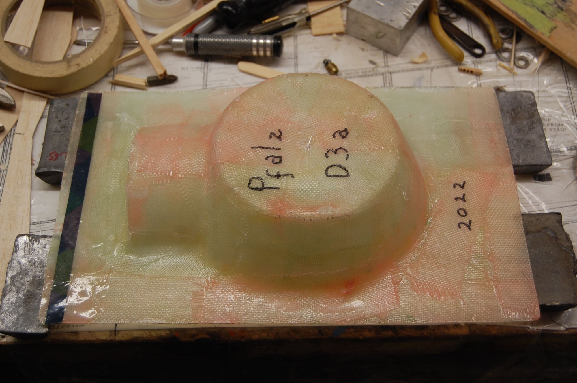
Wow!, only a month between posts. I'm moving right along. I finished up the plug for the nose bowl and got hold of some West Systems resin from a fellow modeler. The plug was painted with several coats of rattle can paint and wet sanded. Once that was really good and dry it was given four coats of wax and a couple of coats of mold release. A little blast of compressed air and the mold popped off easily. I laid up the first nose bowl today. The resin is dry to the touch but I will wait until tomorrow to mess with it so that I don't stress it while it is still too green.
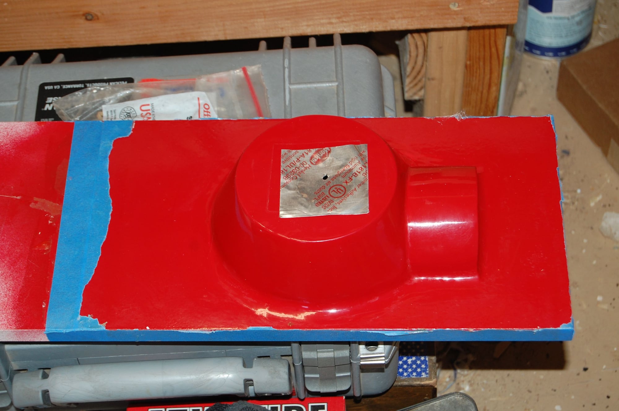
Not a perfect plug but still happy that the mold came off with no damage.
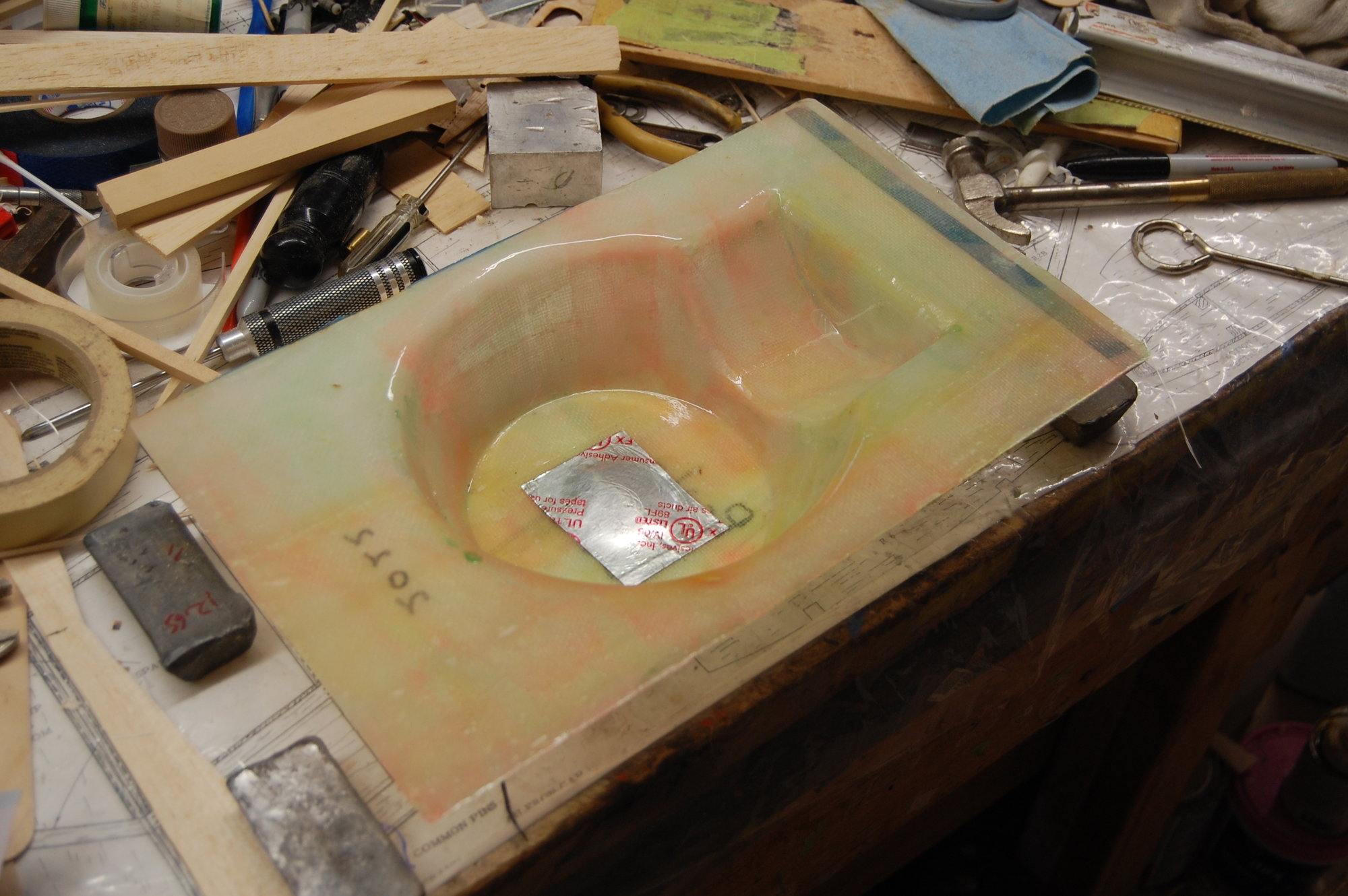
Waxed and coated with PVA mold release. Ready for the layup.
Not a perfect plug but still happy that the mold came off with no damage.
Waxed and coated with PVA mold release. Ready for the layup.
