


DerJET EA6b Prowler build
 07-24-2018, 04:36 AM
#1

Thread Starter
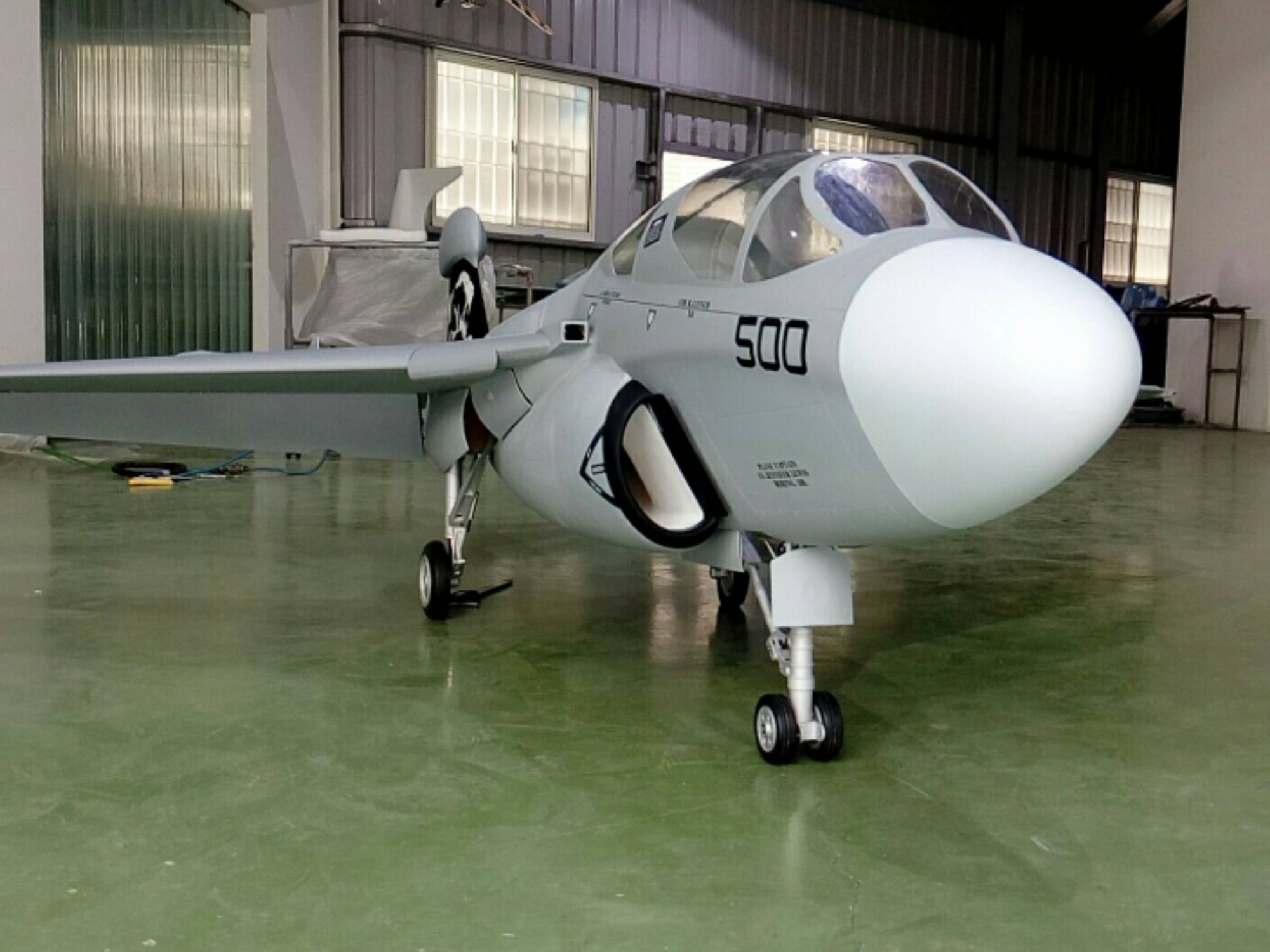
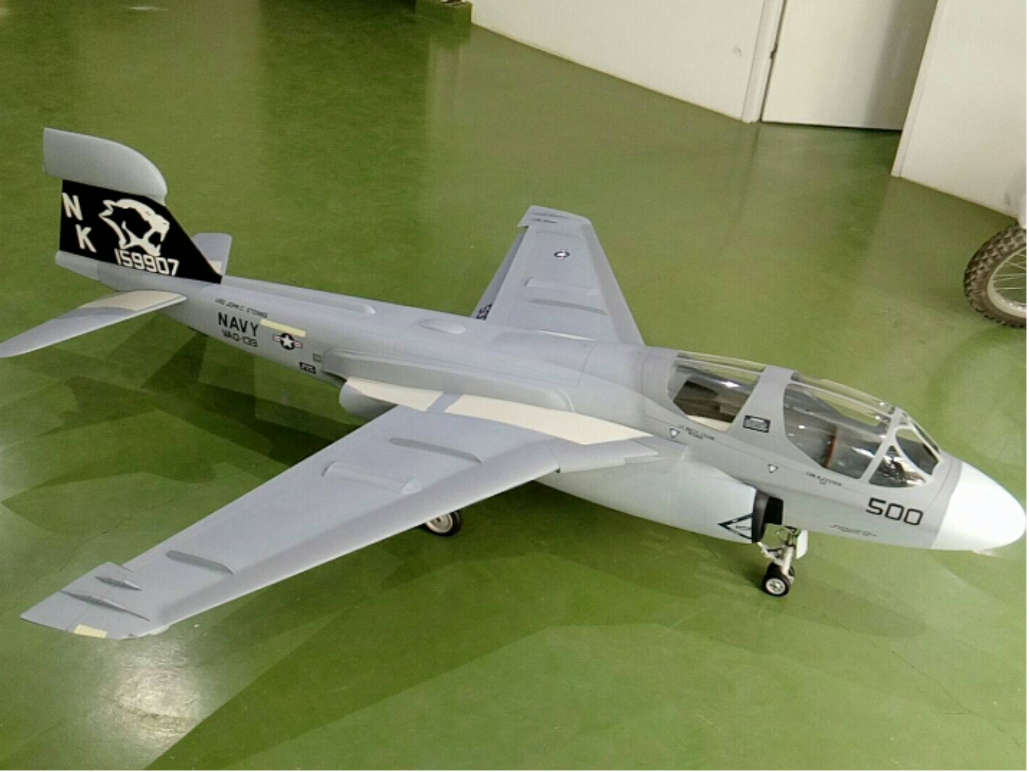
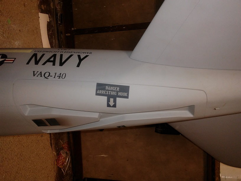
I received my DerJET EA6b Prowler at Kentucky Jets, what a sweet airplane. The Prowler is the 4 seat version of the Intruder, longer fuselage should make CG a bit easier. This is a large twin model, wingspan of 96-1/2", and an overall length of 107", about the same size as my Vixen. This is the prototype so I need to complete the build in a timely many, so here goes.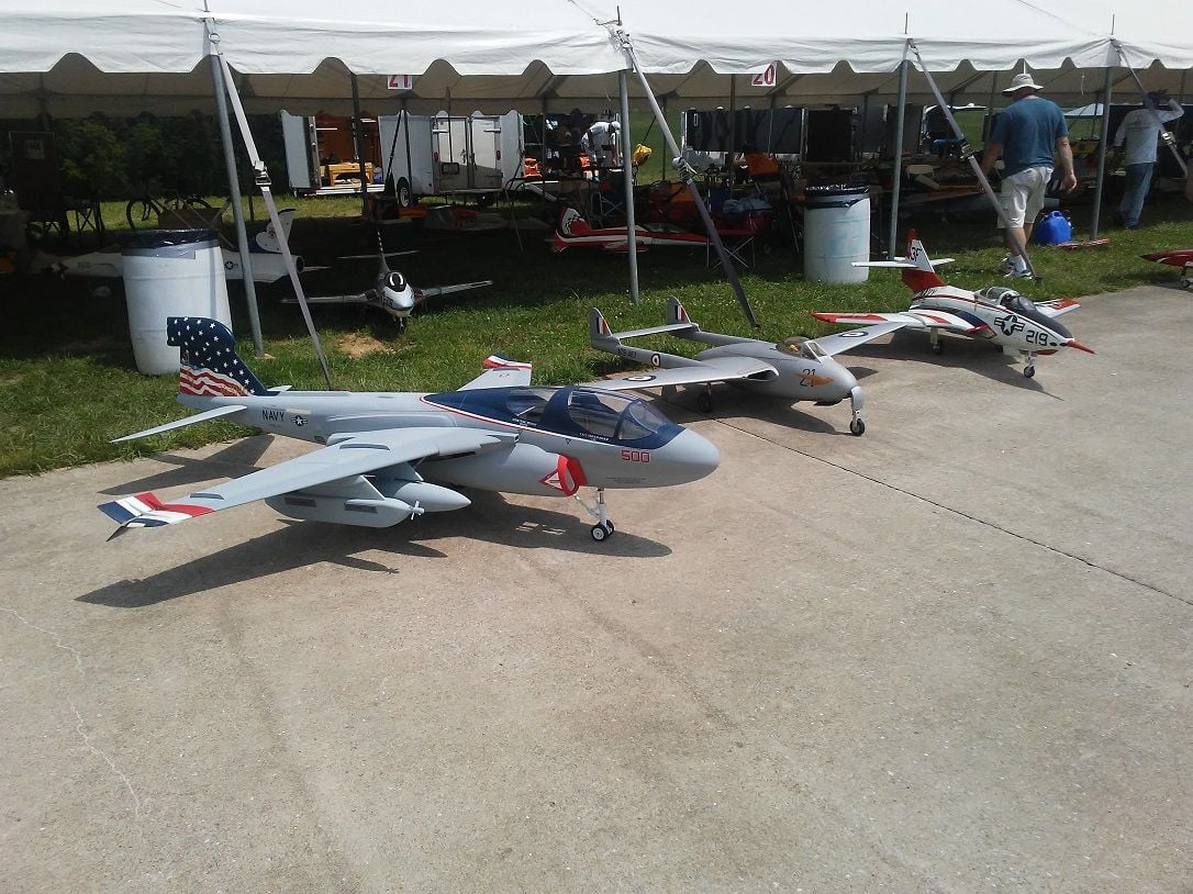
This the Prowler alongside my well worn DerJET Vampire and Cougar, this is a good size jet.
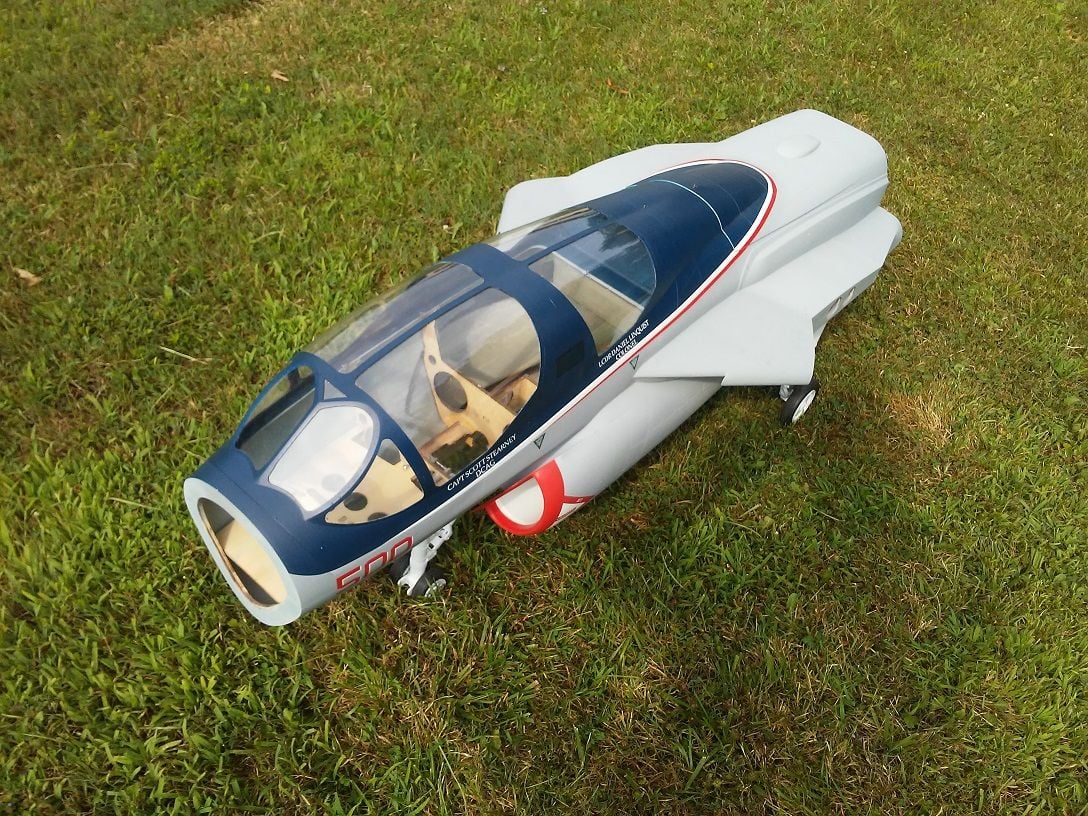
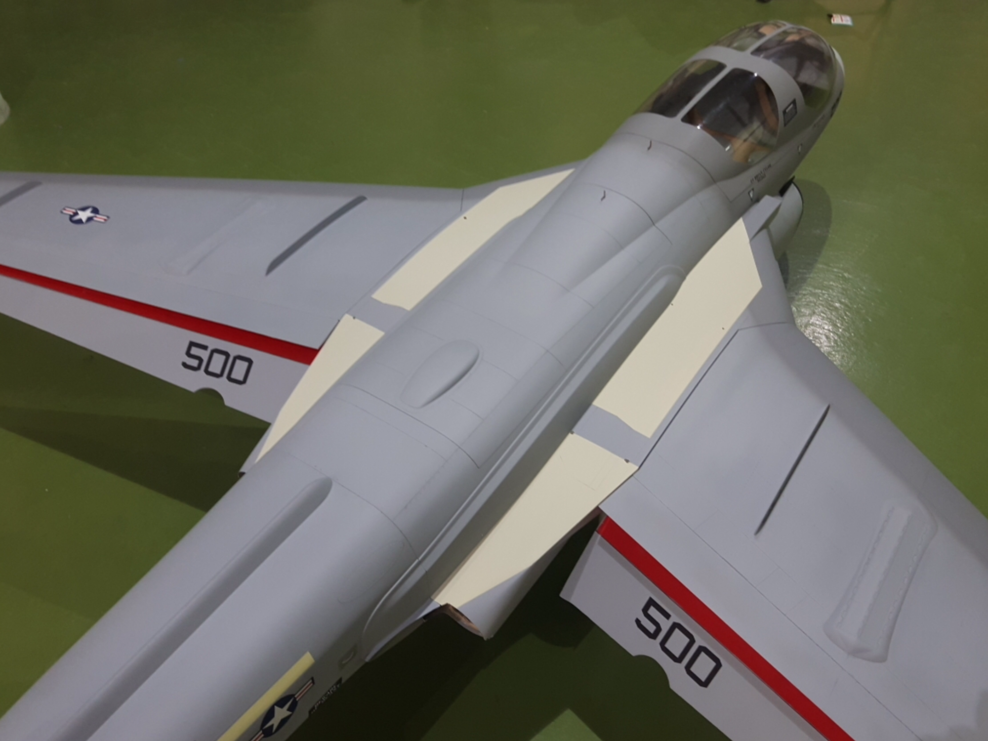
Main body of the Prowler fits nice on the work table, most of the build is here.
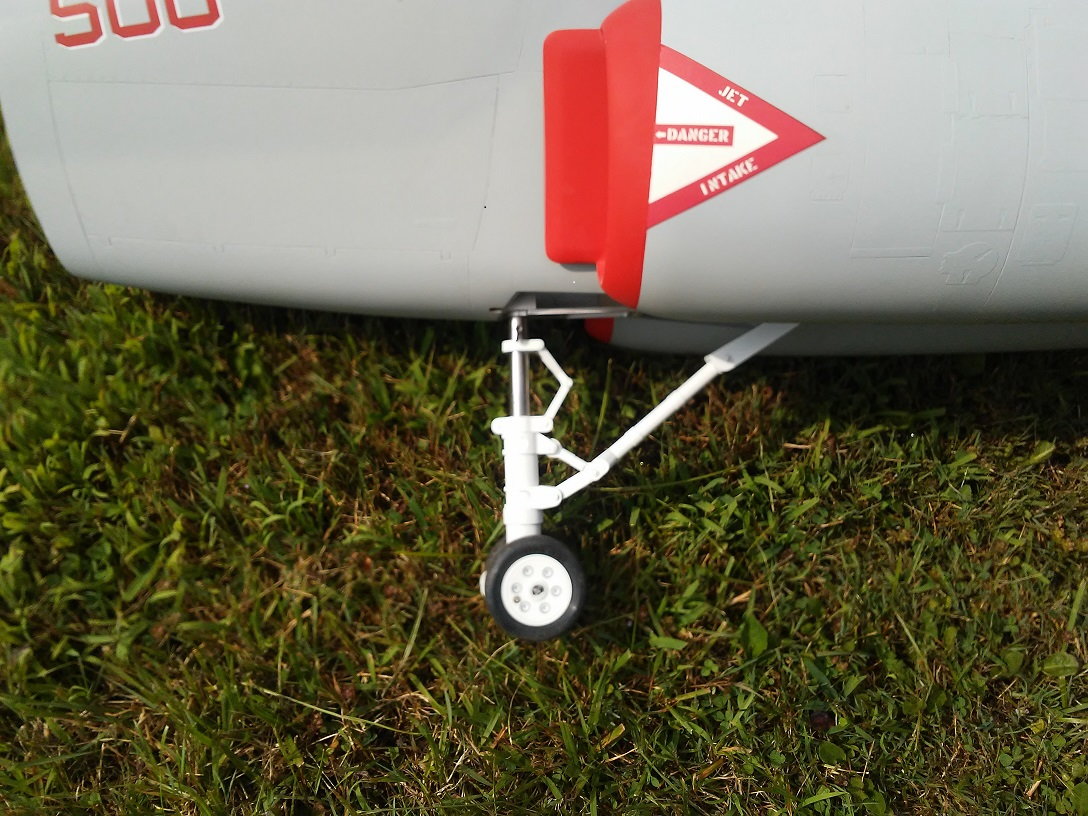
Good looking nose gear, servo is mounted on the strut for positive steering.
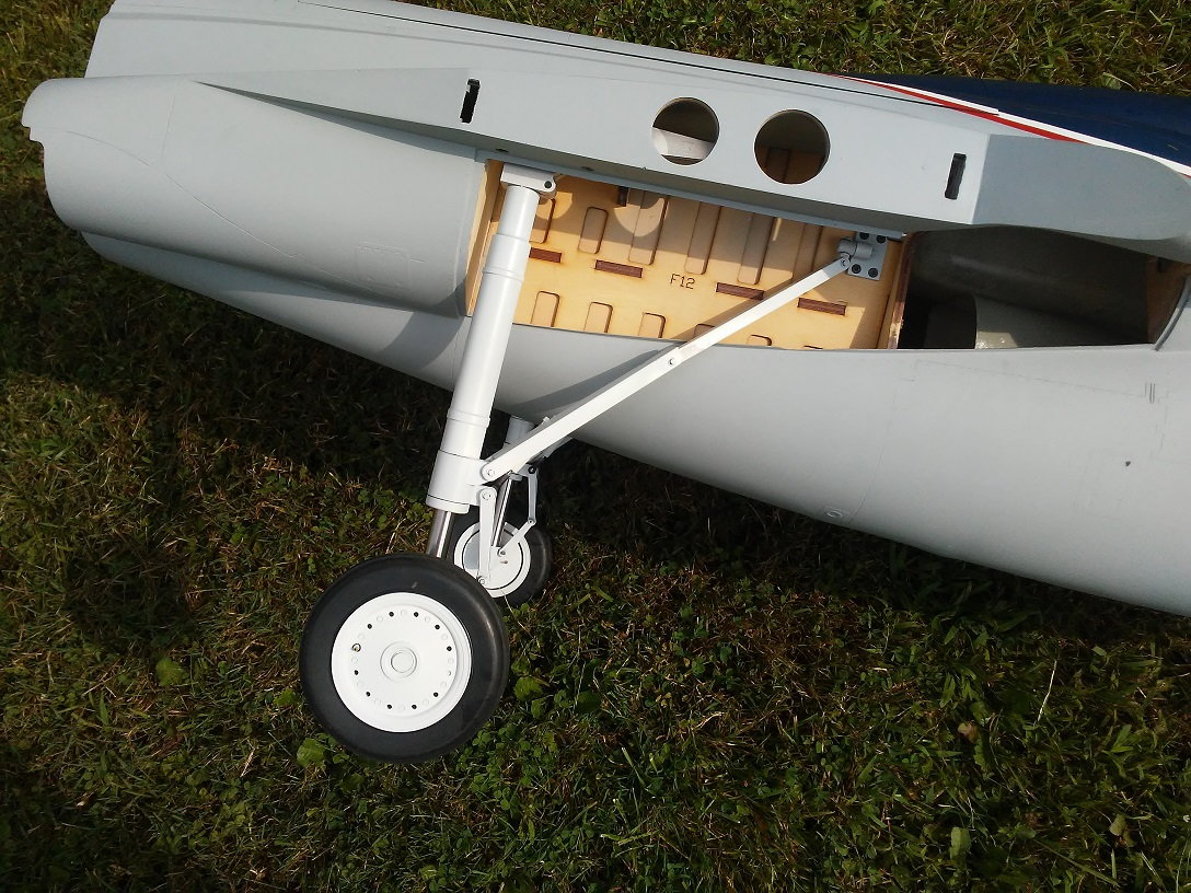
The main gear is mounted solid, and is setup to rotate 90 degrees as it fits up into the wheel well, all the gear doors are included in the kit.
This the Prowler alongside my well worn DerJET Vampire and Cougar, this is a good size jet.
Main body of the Prowler fits nice on the work table, most of the build is here.
Good looking nose gear, servo is mounted on the strut for positive steering.
The main gear is mounted solid, and is setup to rotate 90 degrees as it fits up into the wheel well, all the gear doors are included in the kit.


 07-24-2018, 05:20 AM
#3
Thread Starter
Nice idea, haven't even thought about weathering and detailing yet, still ordering equipment for the build. Like the thought, any ideas on gold tinting.

 07-25-2018, 05:14 AM
#7
Thread Starter
Yesterday was gear door day, well at least half of them, the nose gear strut doors and the main gear wheel doors, all with air cylinders for movement. Starting with the nose gear, the simple install.[img][/img]
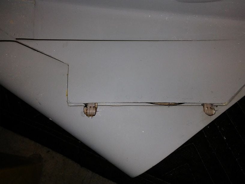
Nose gear strut doors use a simple flat hinge, bolted directly to the plywood side plates, straight forward air cylinder install with a 1/4" basswood spacer added to former.
Nose gear strut doors use a simple flat hinge, bolted directly to the plywood side plates, straight forward air cylinder install with a 1/4" basswood spacer added to former.
07-25-2018, 05:25 AM
#8
Thread Starter
Main gear wheel doors are a bit fiddly, it is a tight fit of the tire going into the wheel well while rotating, but in the end it all fit. Next time I would move the door hinge point outward another 1/8" for additional tire to door clearance.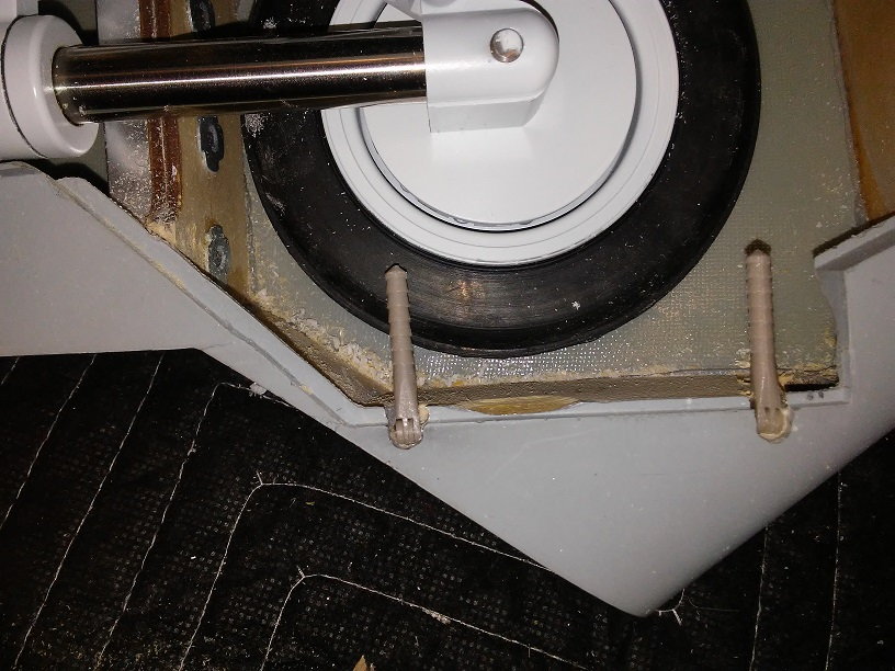
The small clearance cut along the hinge line is for tire clearance, as it rotates it really does move outward that far.
The door rib was hitting the tire during the retraction cycle so had to remove one rib, this is why next time I would move the hinge line out 1/8"
Final install of main gear wheel well went well, note the large gap at hinge line required for gear door to clearance in open position, another reason to move the hinge line out 1/8"
 07-27-2018, 02:00 PM
#15
Thread Starter
Spent yesterday without electricity, love living in the country, right after breakfast the transformer blew on the pole, 6 hrs. later that got fixed, just before the rain came, well that created an area wide electrical outage, finally at 2:00 am finally got power, generator got a work out. Today was better day, completed the wings today, servos and air cylinder completed and hatches closed up, and programming completed for the spoilers and flaps.
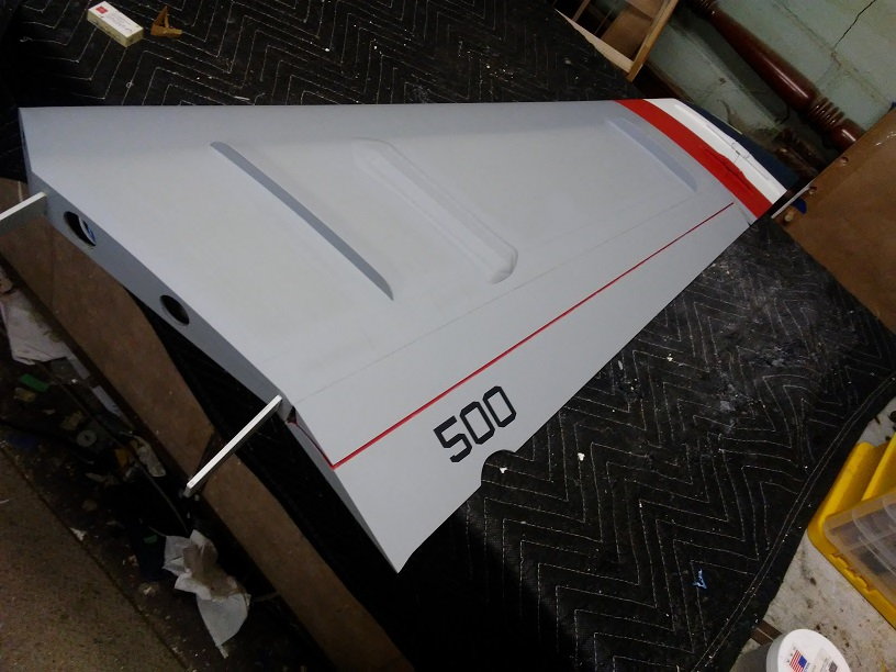
Roll control is with spoilers, and large almost full span flaps, this will be my first model airplane experience with spoiier roll control, keeps life fun.
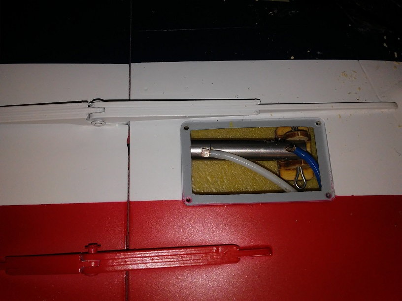
Flap and spoiler servos mount in a nice servo pocket, provide control linkages are rod ends at servo end, pretty clean but fiddly adjusting linkage in this tight spot, but all worked out well.
Roll control is with spoilers, and large almost full span flaps, this will be my first model airplane experience with spoiier roll control, keeps life fun.
Flap and spoiler servos mount in a nice servo pocket, provide control linkages are rod ends at servo end, pretty clean but fiddly adjusting linkage in this tight spot, but all worked out well.
07-27-2018, 02:16 PM
#16
Thread Starter
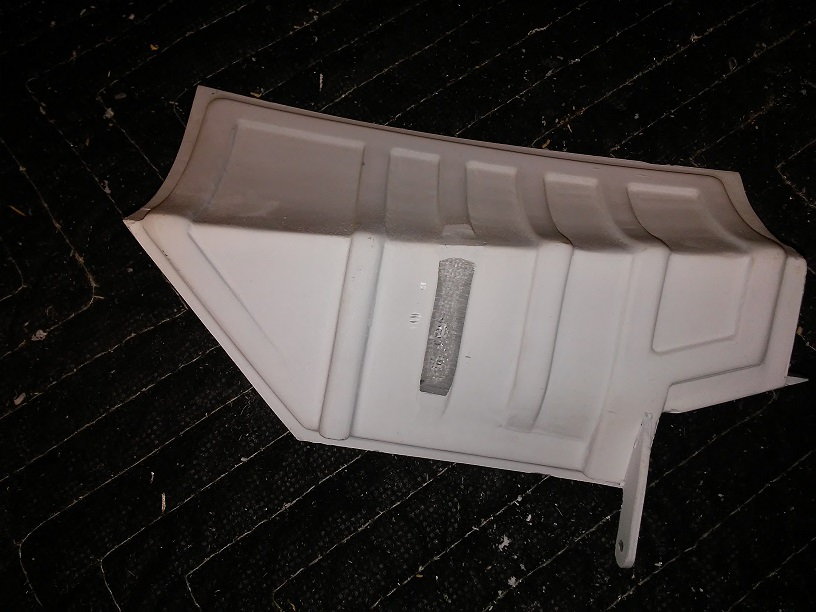
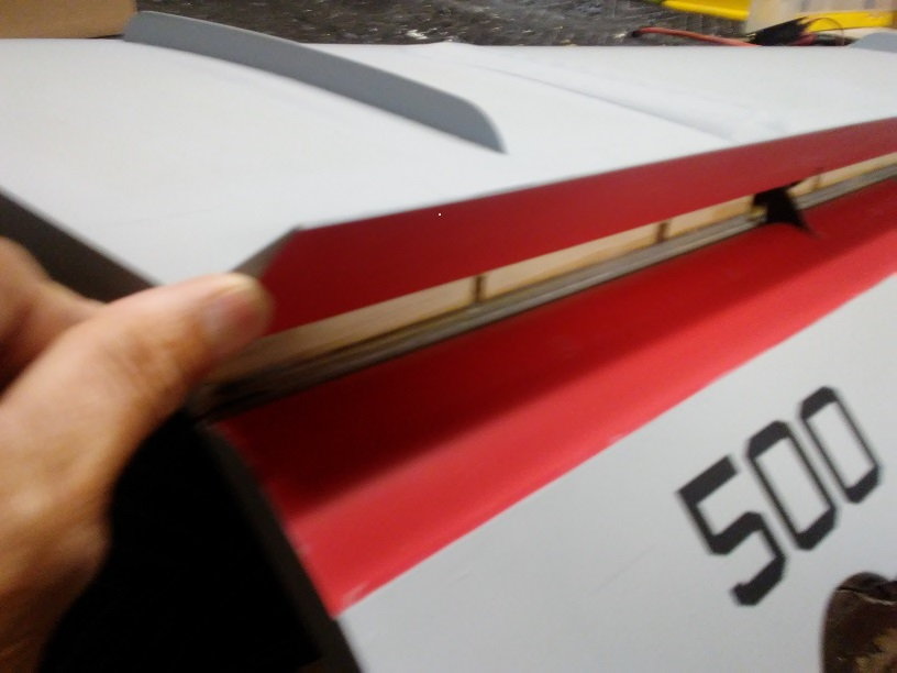
Speed boards in open position, easy install as pre-hinged.
Air cylinder to move the speed boards install was straight forward, the air lines were already installed and ready to hookup to the air cylinder, small pocket but easy install.
Speed board installation was very straight forward, the air lines were already in place so it was simply assemble the air cylinder, hook up the linkage, then epoxy in place, they do look cool when spread open.
07-28-2018, 04:30 AM
#18
Thread Starter
I don't ever want to find out, those drag brakes are located at the wingtips, suspect it would be uncontrollable in yaw, only option would be to close immediately if that happens. My Vampire has speed boards outboard on the wing and to be honest every time I deploy them I am very watchful to see the aircraft does not do anything funny keeping my finger on the switch for a second or two until confident all is deployed evenly.
07-30-2018, 07:22 AM
#19
Thread Starter
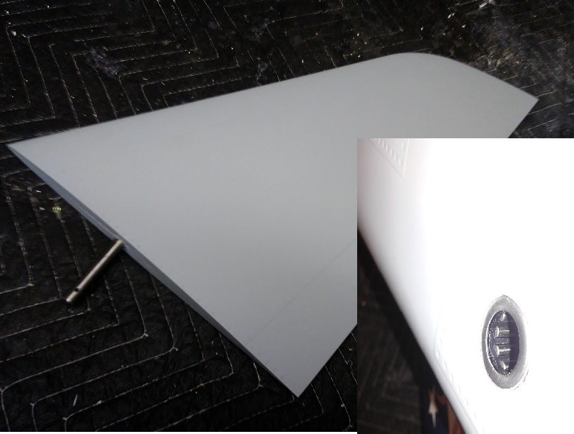
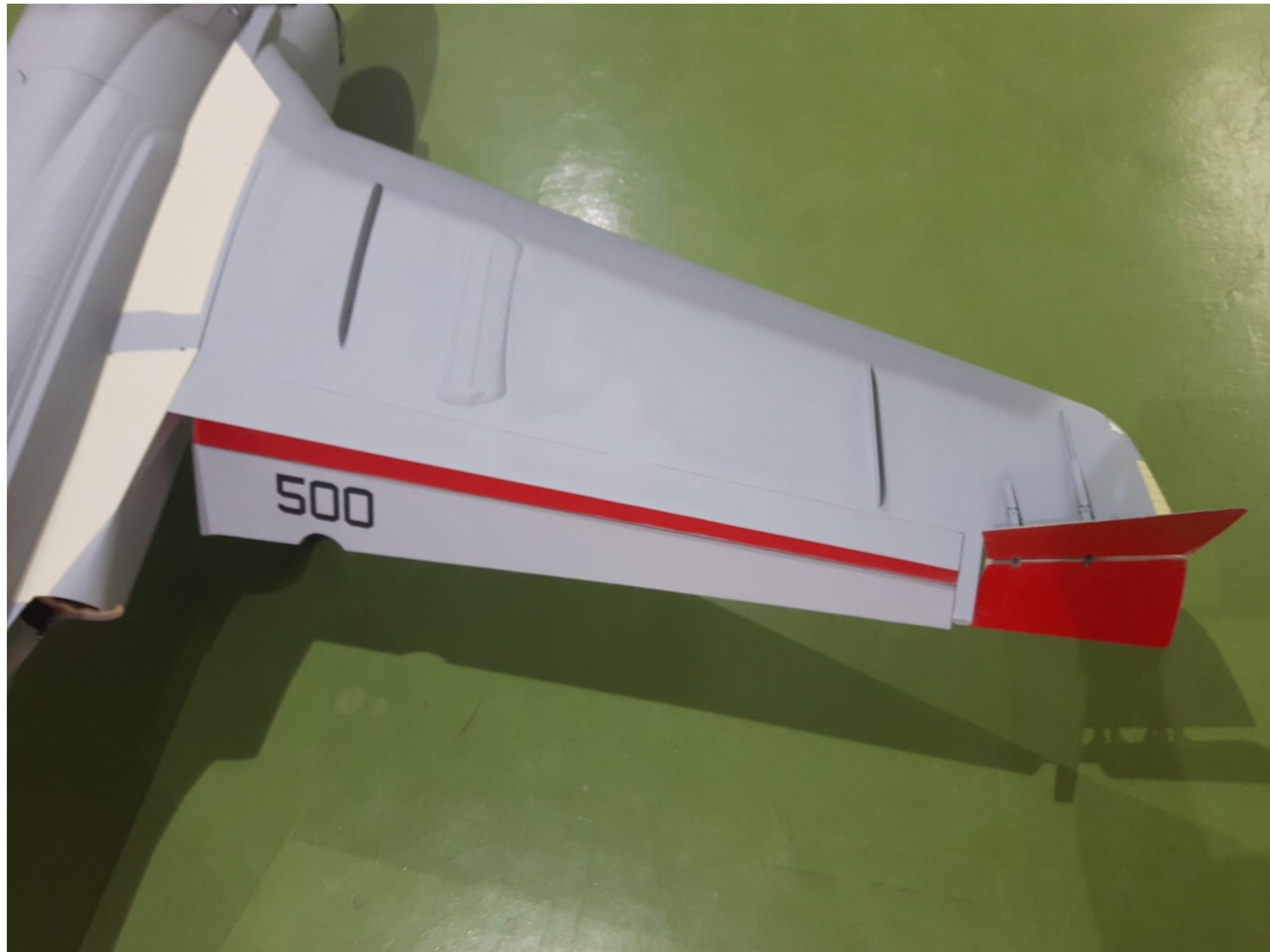
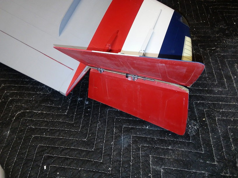
Full flying stab, nice roller bearings for hinge.
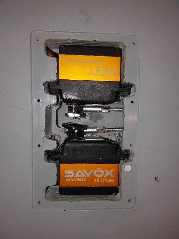
Servo bay hatch for Rudder and Elevator servos is located underneath, nice large opening for easy work.
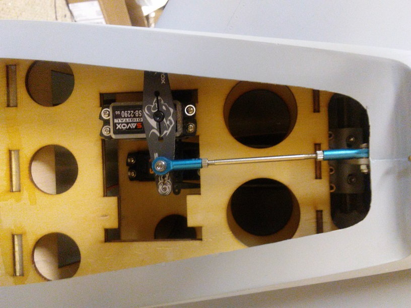
How's this for plenty of room, a two story servo bay, upper servo is the rudder servo, cables to rudder, and lower is the elevator servo, using an almost 700 in-oz. servo.
Completed the tail section systems installs, ok that means the elevator and rudder, very straight forward and easy.
 07-30-2018, 09:37 AM
#21
 07-30-2018, 01:16 PM
#22
Full flying stab, nice roller bearings for hinge.
Servo bay hatch for Rudder and Elevator servos is located underneath, nice large opening for easy work.
How's this for plenty of room, a two story servo bay, upper servo is the rudder servo, cables to rudder, and lower is the elevator servo, using an almost 700 in-oz. servo.
Completed the tail section systems installs, ok that means the elevator and rudder, very straight forward and easy.
Dave
07-30-2018, 03:06 PM
#23
Thread Starter
Dave, not sure I understand your concern, those are rod ends, they have some limited travel in the alignment angle to accommodate the movement it sees when moving.
07-30-2018, 03:55 PM
#24
If that is the stab servo above, I would highly recommend some stronger rods and move the rod end on the servo arm down to about 10-15mm from center to help with leverage. Also beef up the ply the servo is mounted to, that looks like the soft ply. Just some tips for success on a new model release.
Last edited by FenderBean; 07-30-2018 at 03:58 PM.
07-31-2018, 08:34 AM
#25
Thread Starter
I appreciate your concerns, your unable t see in the picture but the elevator servo tray is typical 3 ply plywood 1/8" thick, reinforced in the are of the servo with a 2nd layer of 1/8" plywood, total of 1/4" thick, very rigid with a lot of load distribution so not concerned structure in this area, and yes I have lost a 3d airplane when the rudder servo mounting tray failed, so I am sensitive to this issue.
The elevator control arm is almost 2" tall, very rugged, and your right the final location of the rod end on the servo arm has yet to be setup, I want about 20 degrees of up elevator travel at 100% travel, that's my plan to determine the hole on the servo arm that will get used. FYI the full scale Prowler flight manual states 17 degrees of elevator travel normal with 20 degrees available for spin recovery, so that's my plan on elevator travel dual rate setup, should be plenty. I will use the hole closest to the servo pivot to get maximum leverage, this servo is rated at almost 700 in-oz. of torque and I want it all.
The elevator control arm is almost 2" tall, very rugged, and your right the final location of the rod end on the servo arm has yet to be setup, I want about 20 degrees of up elevator travel at 100% travel, that's my plan to determine the hole on the servo arm that will get used. FYI the full scale Prowler flight manual states 17 degrees of elevator travel normal with 20 degrees available for spin recovery, so that's my plan on elevator travel dual rate setup, should be plenty. I will use the hole closest to the servo pivot to get maximum leverage, this servo is rated at almost 700 in-oz. of torque and I want it all.