


BIG A-5 Vigilante build
 11-26-2018, 07:04 PM
#526

Thread Starter
Join Date: Mar 2009
Location: willow springs , IL
Posts: 1,222
Likes: 0
Received 25 Likes
on
14 Posts
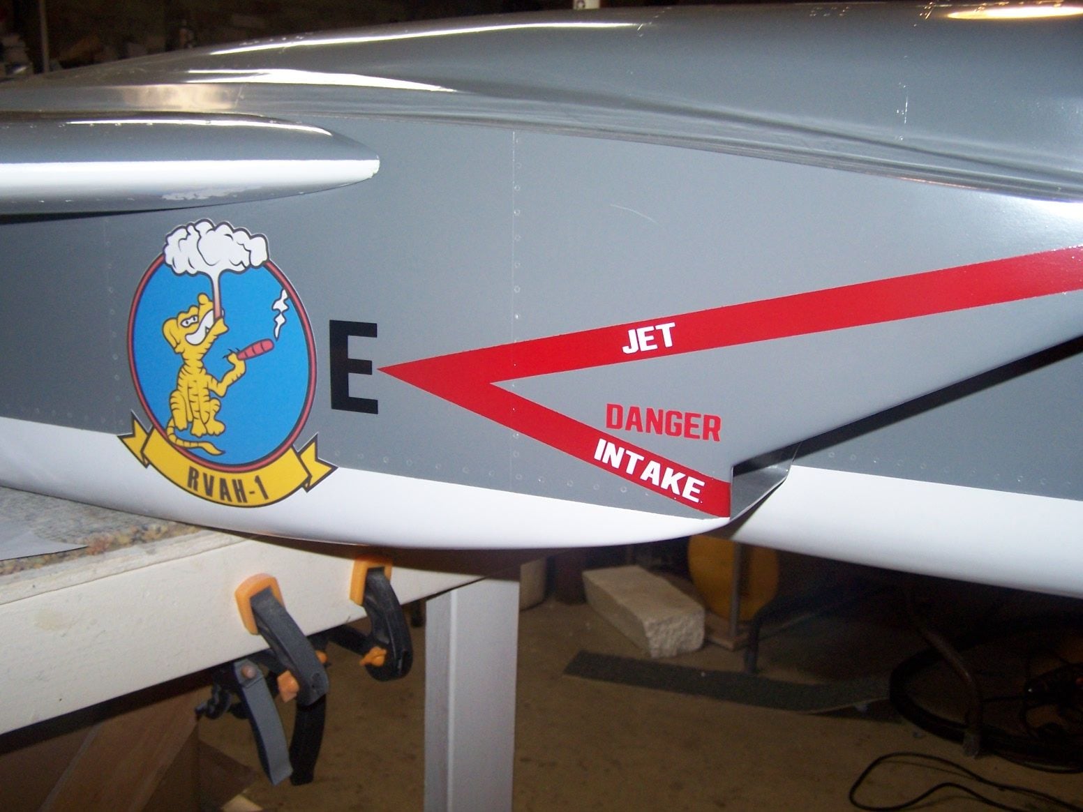
here they are on the plane. I don't know if they are Jet A proof but I am not going to seal them. If they fade or get ruined I will print and cut another set. They were cheap and quick to make.
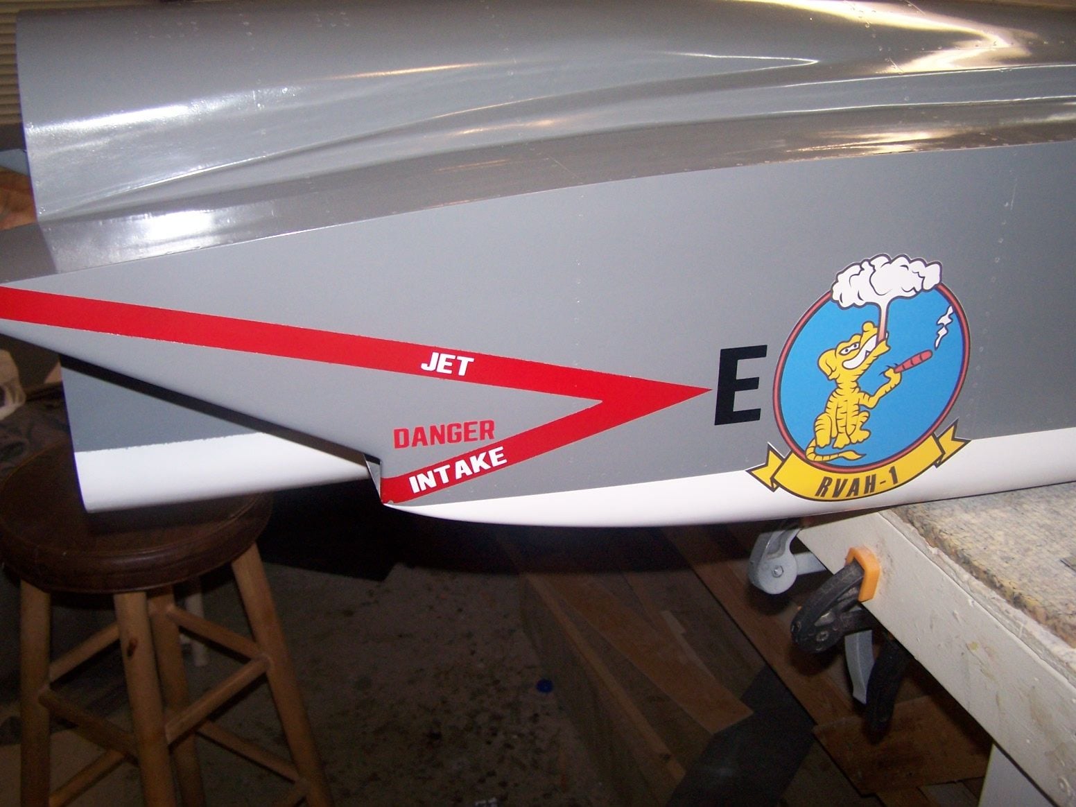
Left intake
 12-02-2018, 09:46 PM
#527
Thread Starter
Join Date: Mar 2009
Location: willow springs , IL
Posts: 1,222
Likes: 0
Received 25 Likes
on
14 Posts

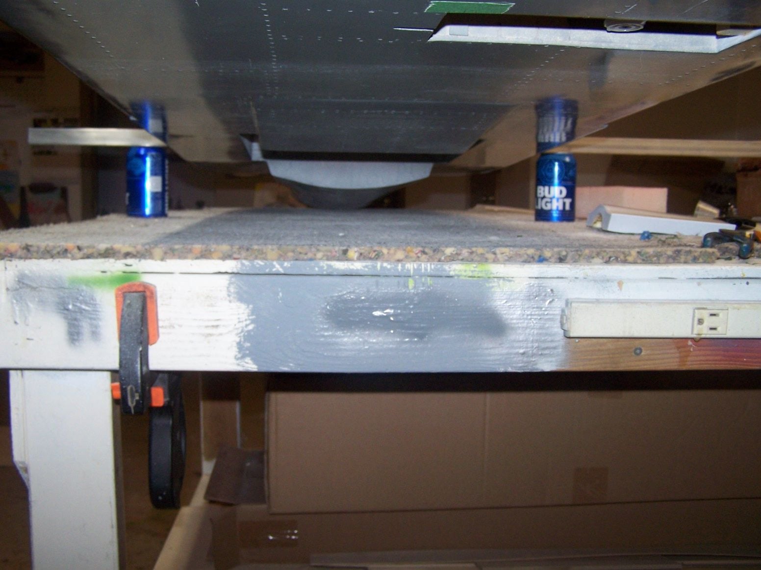
I propped up the fuse on the front spar. It is 6" in front of the CG. The fuse. tipped very nose heavy. I think that is good at this point since there are quite a few things that will be behind the CG.
Hopefully I can balance the plane by shifting things in the plane to spare adding lead. But we will see.
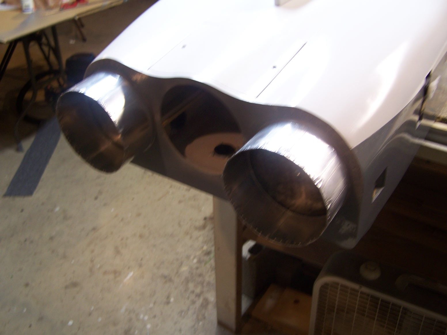
I bolted the dummy turkey feathers on the back
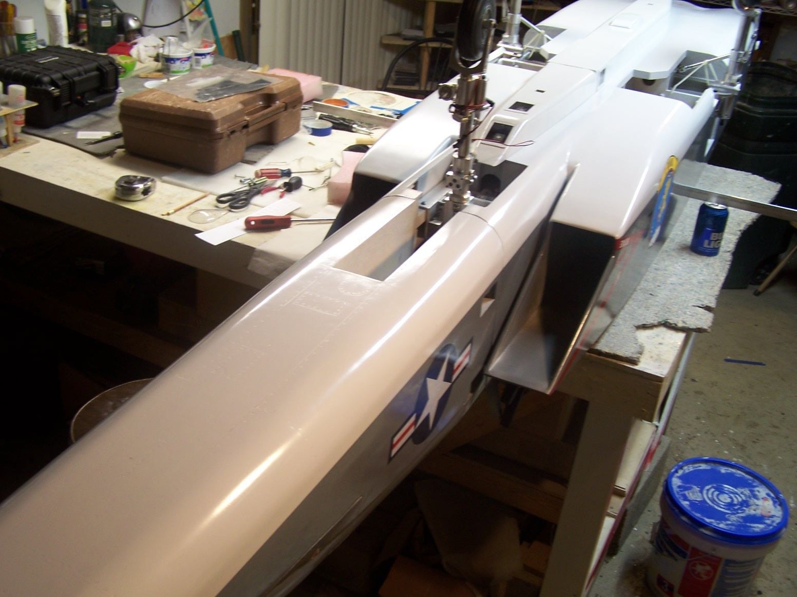
I also bolted thee nose on and installed the landing gear.
I made a paper template of the back of the fuse. I will start stacking some blocks of urethane foam to create the fairings on the back of the fuse.

 12-05-2018, 09:38 PM
#531
Thread Starter
Join Date: Mar 2009
Location: willow springs , IL
Posts: 1,222
Likes: 0
Received 25 Likes
on
14 Posts
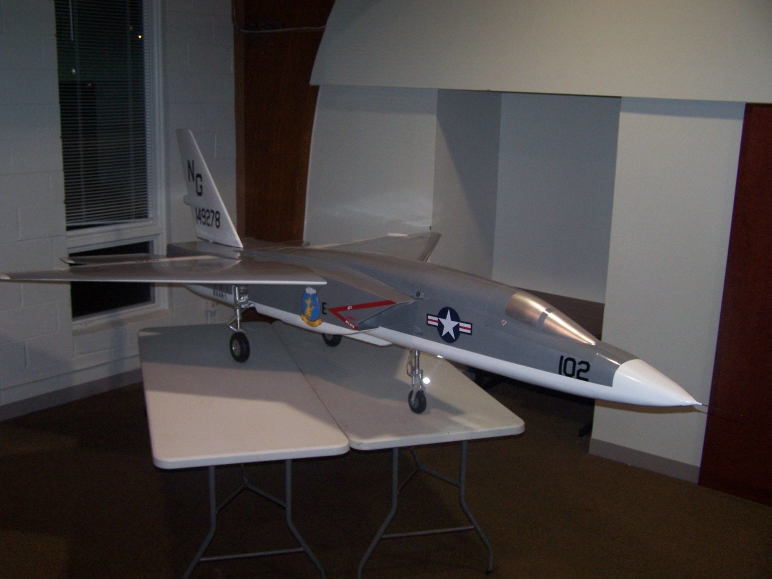
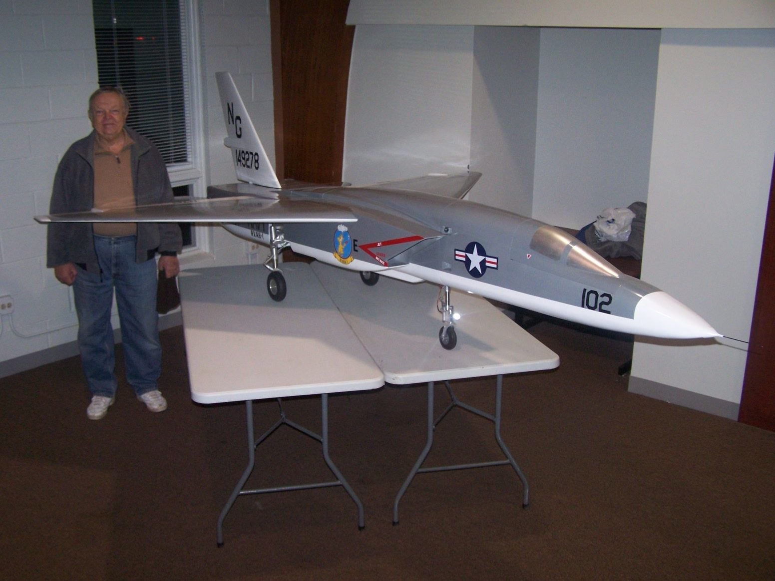
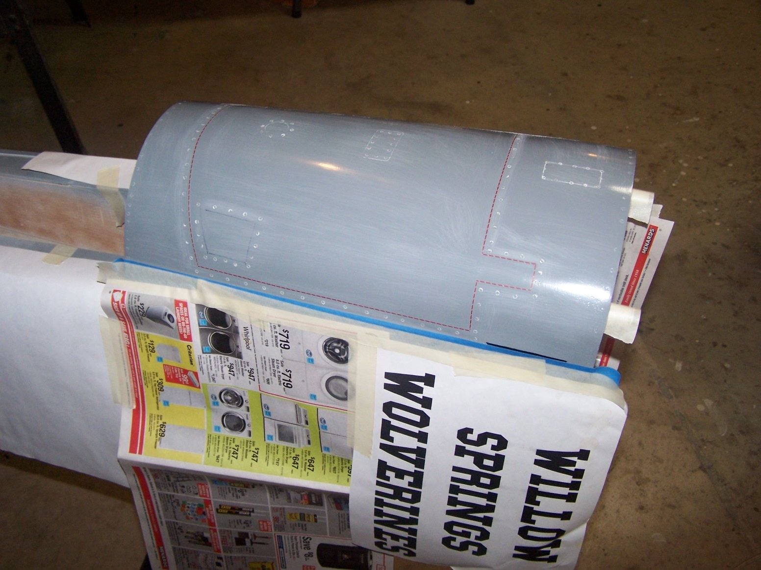
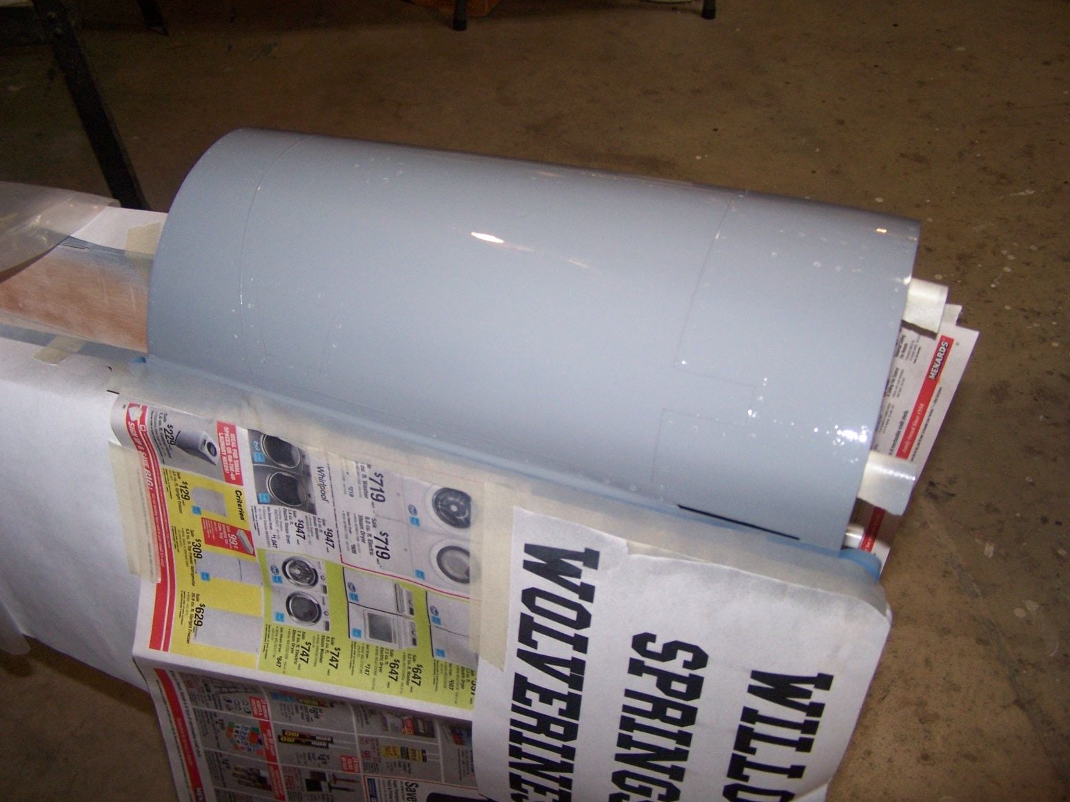
Thanks all for the words of encouragement... Here is a picture of the plane all put together at our club meeting tonight. I was pleased to learn the plane assembled with the engine installed in the tail it balances very close to on the money. It sits on the gear nice with the CG in front of the mains very close to where it should be. Everything left to go in the plane will install through the top hatch on or close to the CG. The second picture is of Vladimir next to the plane. He is the man to credit for making the beautiful landing gear for the Vigilante.

 12-16-2018, 10:00 PM
#535
Thread Starter
Join Date: Mar 2009
Location: willow springs , IL
Posts: 1,222
Likes: 0
Received 25 Likes
on
14 Posts
I have a plumbing question. I was thinking about using two 100oz. Dubro tanks for fuel. There are two ways to plumb them. The first would be to have two pick up lines teed to the pump. The second would have one pick up line and the other tank feeding the pick up tank. What has been peoples experience and what are the pros and cons.
12-17-2018, 08:23 AM
#536
My Feedback: (1)
Join Date: Sep 2003
Location: Talamanca de JaramaMadrid, SPAIN
Posts: 583
Received 4 Likes
on
4 Posts
Congrats Joe for the Vigilante!.
Regarding your question, you must know parallel plumbing the fuel tanks has a greater risk of feeding air to the turbine and instantly killing it. On the other hand, series plumbing them reduces this risk although you may have troubles with weight distribution as fuel is used.
If it is the case, best solution should parallel connect both main tanks to a smaller feeder or UAT one which will connect to the turbine pump.
I wish you the greatest success when you go for maidening your Vigilante!.
Best Regards.
12-19-2018, 05:49 PM
#537
Thread Starter
Join Date: Mar 2009
Location: willow springs , IL
Posts: 1,222
Likes: 0
Received 25 Likes
on
14 Posts


This is what two 100oz. tanks look like in the plane. They will probably be installed flat and not on edge. Everything else that needs to go in the plane will be above the fuel tanks. I think the best way to plumb them together will be in series. The weight imbalance side to side shouldn't be an issue with the tanks only a few inches off the center line.
 12-23-2018, 08:15 PM
#539
Thread Starter
Join Date: Mar 2009
Location: willow springs , IL
Posts: 1,222
Likes: 0
Received 25 Likes
on
14 Posts

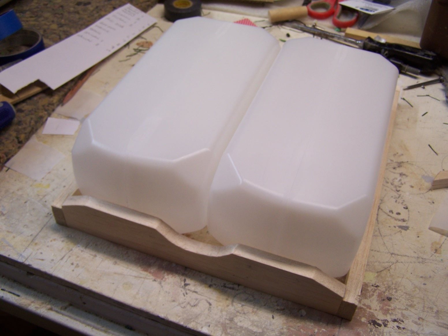
Thanks Redtail. The tint in earlier posts were black and red. It is tint that is available at any store that sells resins and casting material. I made a retention frame to hold the tanks in place and to hopefully contain a spill if it happens. The swail along the back is so I can get my hand and arm into the rear of the fuse to work.
01-04-2019, 07:30 PM
#540
Thread Starter
Join Date: Mar 2009
Location: willow springs , IL
Posts: 1,222
Likes: 0
Received 25 Likes
on
14 Posts

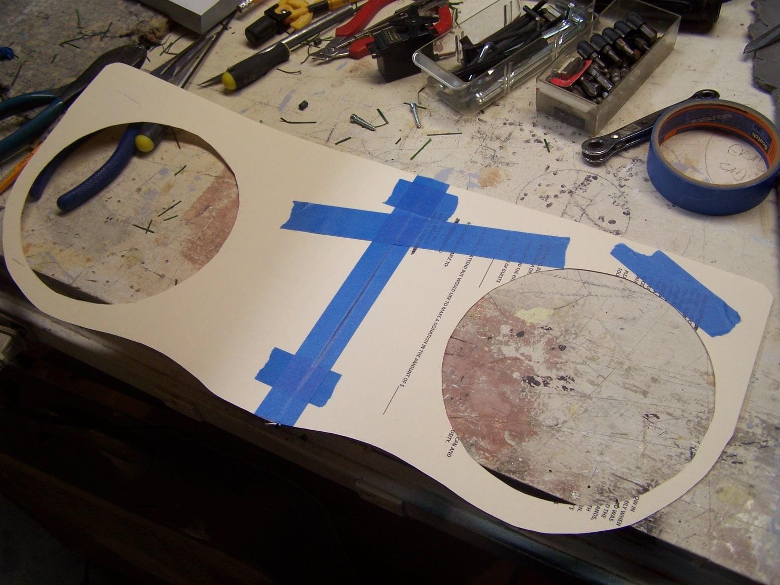
Here is the fuel tank hold down tray that will take the ECU, fuel pump, turbine battery, receiver, and receiver battery. The aluminum angles will get screwed into the sides. The bolts coming up will stay a little ling in case something needs to be bolted on them. The tray will get an air dam on the front to keep everything on the tray out of the air stream.
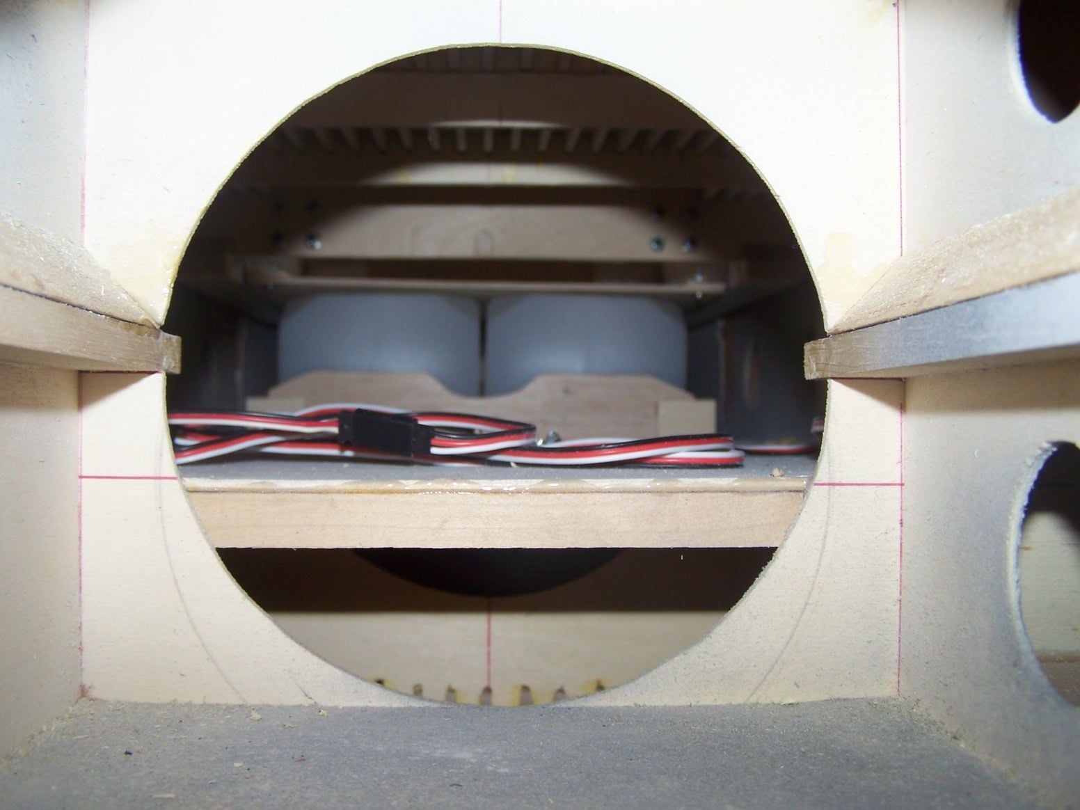
Here is a pic from the engine compartment looking forward.
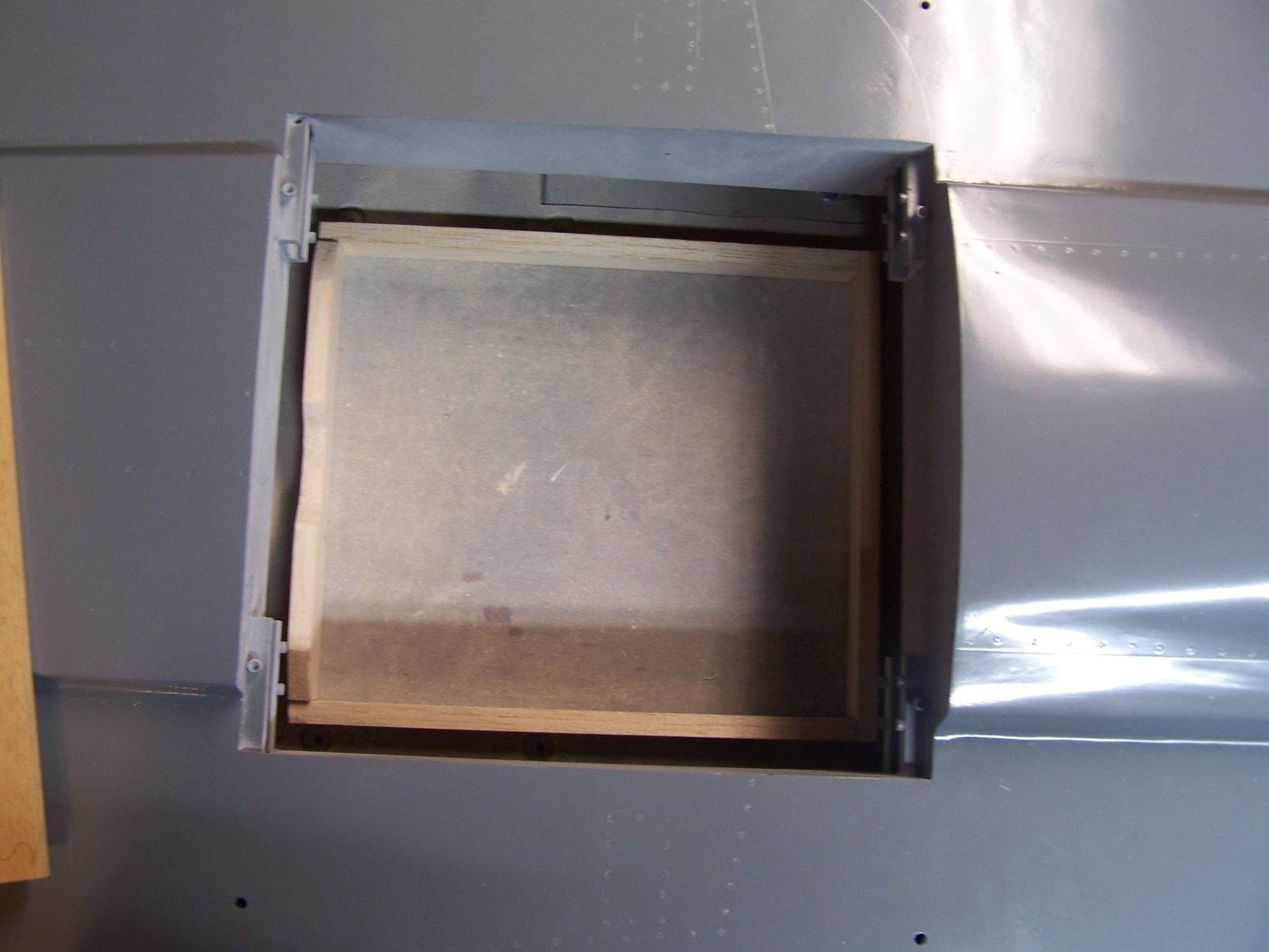
I forgot to frame out a hatch for the back seater. I outlined it with some charting tape and will burn some rivets around it. It will then get another mist of paint.
01-25-2019, 05:55 PM
#541
Thread Starter
Join Date: Mar 2009
Location: willow springs , IL
Posts: 1,222
Likes: 0
Received 25 Likes
on
14 Posts
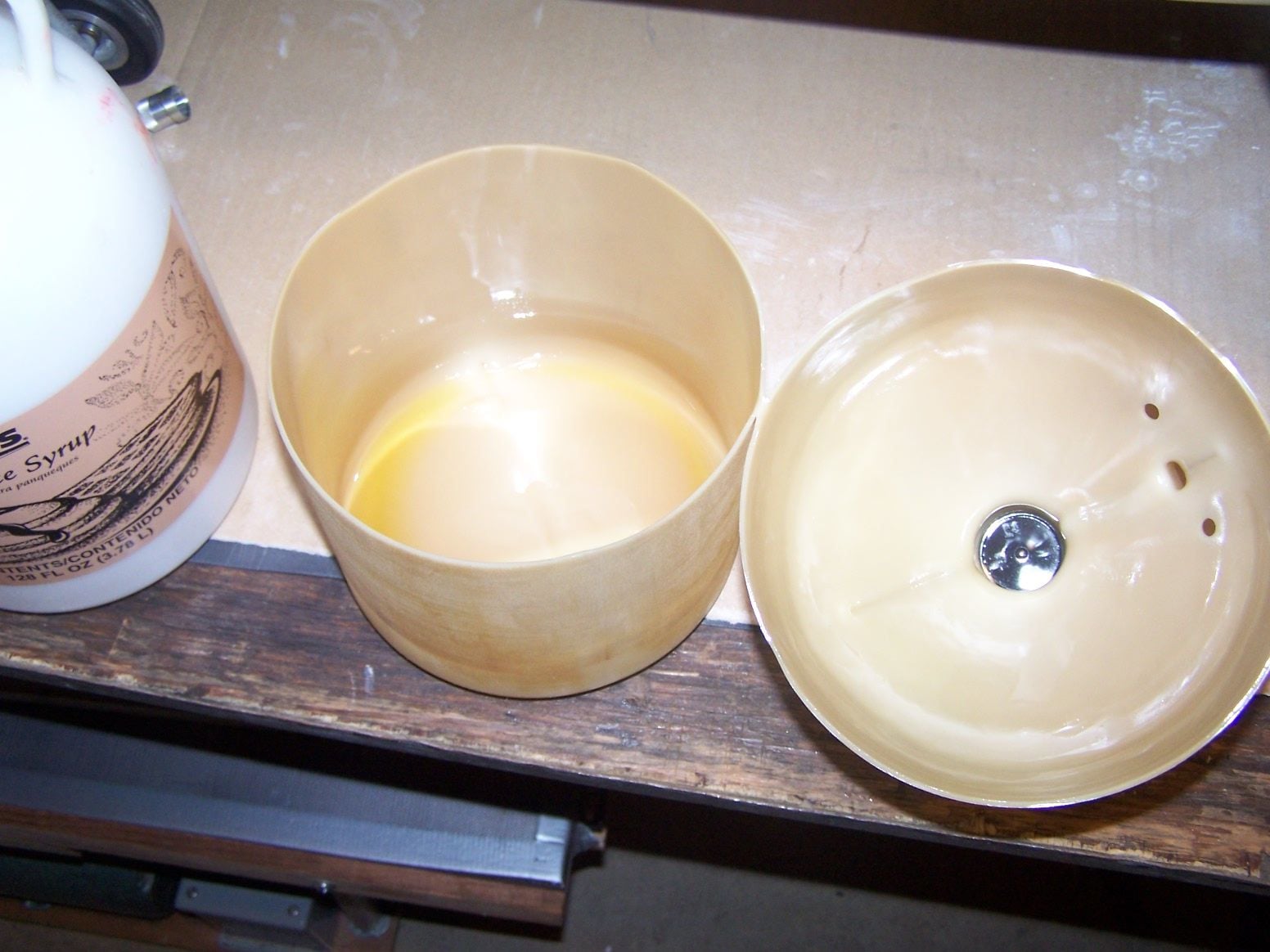
The GFS maple syrup is crazy thick, very heavy duty. I had the vent and pick up lines friction fitted through the wall of the bottle, no fittings. The neoprene with Viton hoses in the tank were like brand new after many years, so I reused them in the new tank. I cut the bottle open to get a good look inside. no garbage or growth, just discolored.
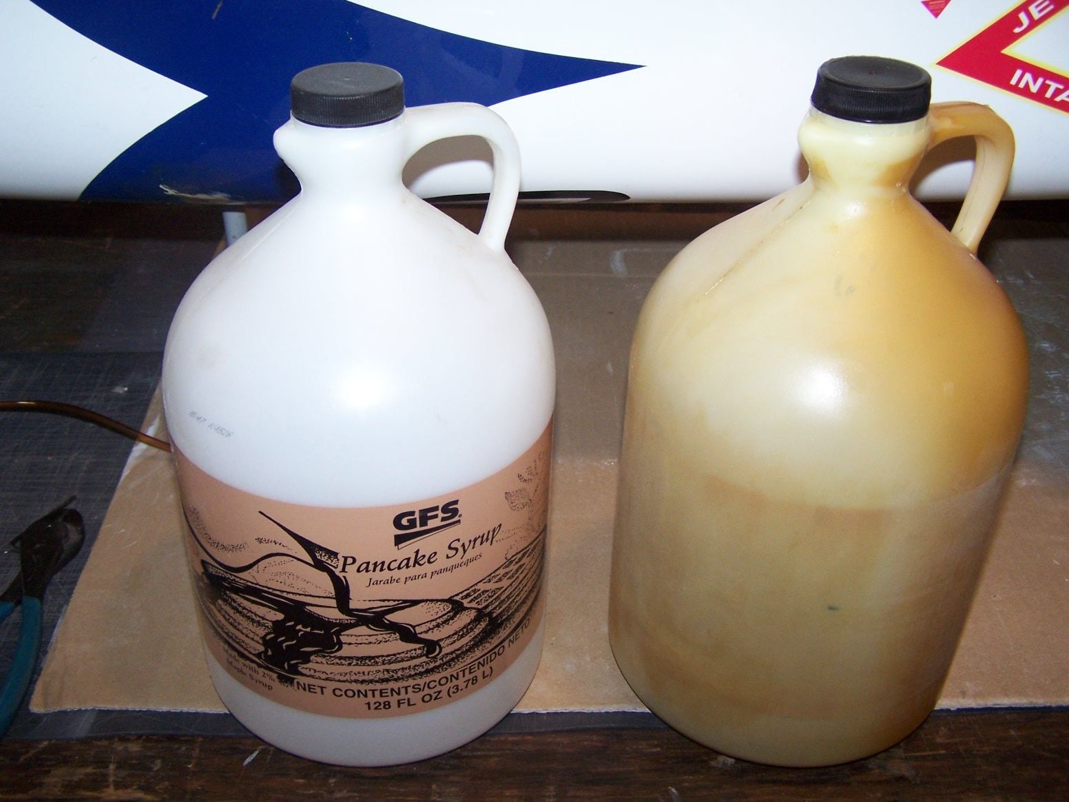
My Boomerang Xl tank needed an update. It finally started leaking under the cap after 13 years.

The wires will get secured in the rear

I opened a hole in the floor to run the servo wires under the floor
I burned some rivets around the back hatch
01-29-2019, 08:37 PM
#542
Thread Starter
Join Date: Mar 2009
Location: willow springs , IL
Posts: 1,222
Likes: 0
Received 25 Likes
on
14 Posts

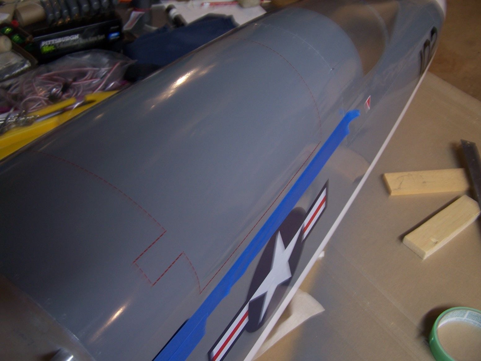
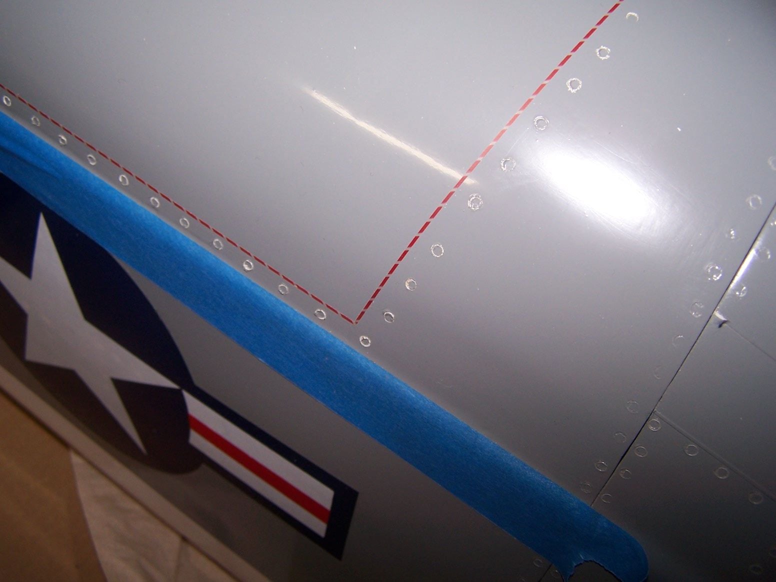
I put more rivets on the rear canopy and located the window
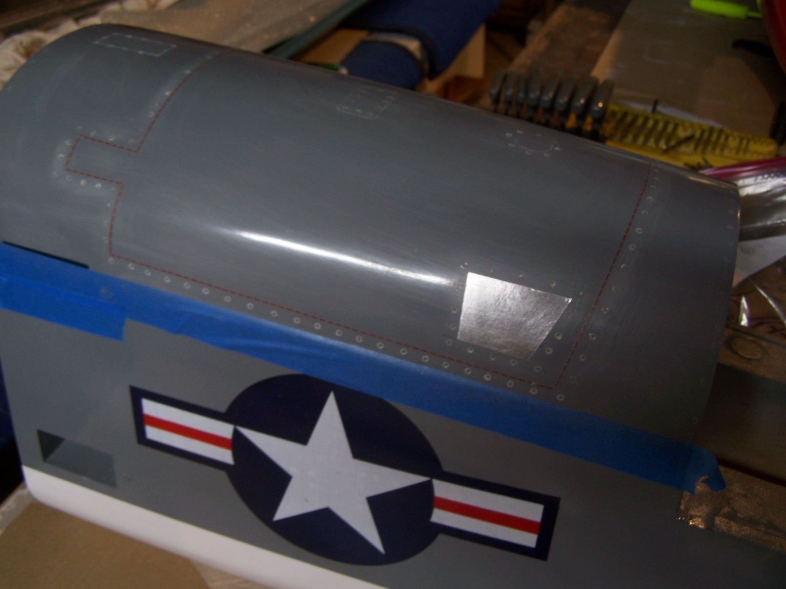
The rear canopy window will be aluminum tape. I just stuck one on there temporarily. It needs to be painted again above the blue tape.
02-03-2019, 02:41 PM
#543
Thread Starter
Join Date: Mar 2009
Location: willow springs , IL
Posts: 1,222
Likes: 0
Received 25 Likes
on
14 Posts
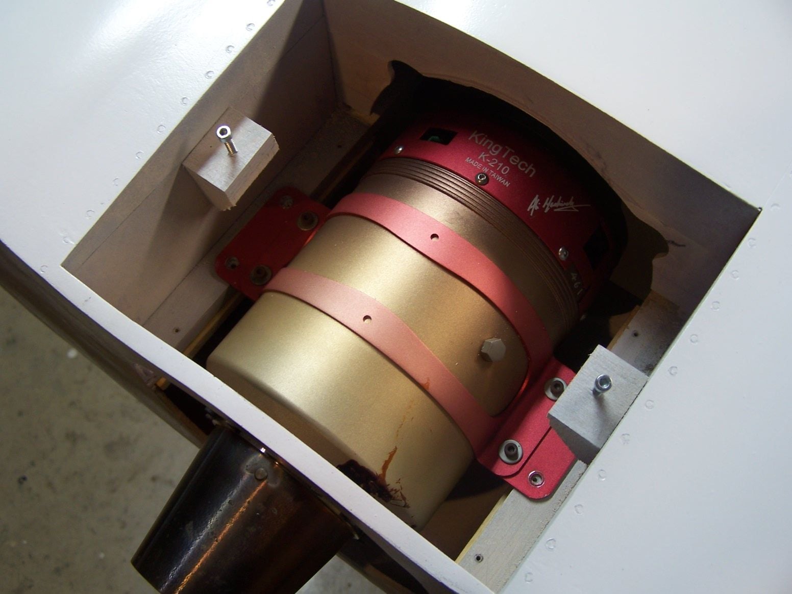
My friend Sebastian talked me into getting a K 210 for this. I think it would fly on a smaller engine but we will see.
A little steel wool for the paint to stick
I masked off and repainted the rear seat hatch area
 02-10-2019, 02:16 PM
#546
Thread Starter
Join Date: Mar 2009
Location: willow springs , IL
Posts: 1,222
Likes: 0
Received 25 Likes
on
14 Posts
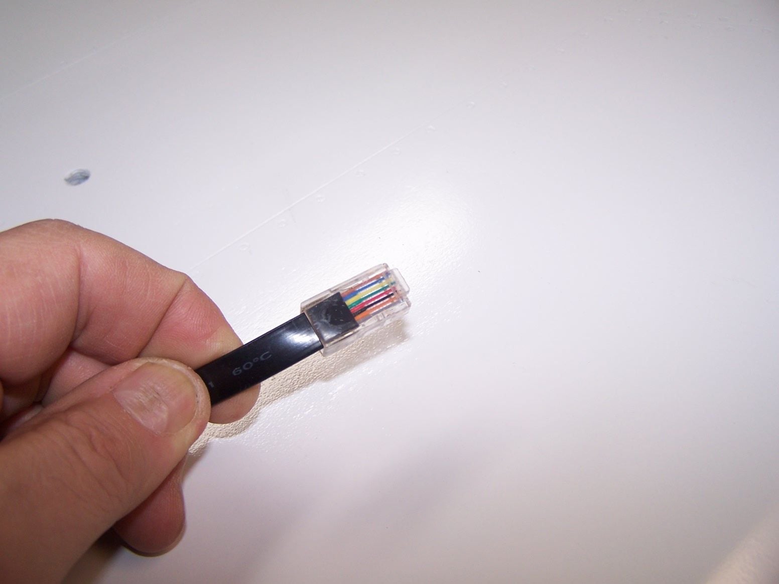
The RJ 45 locking tab is broken of on my cable. I will need to make another and a bit longer
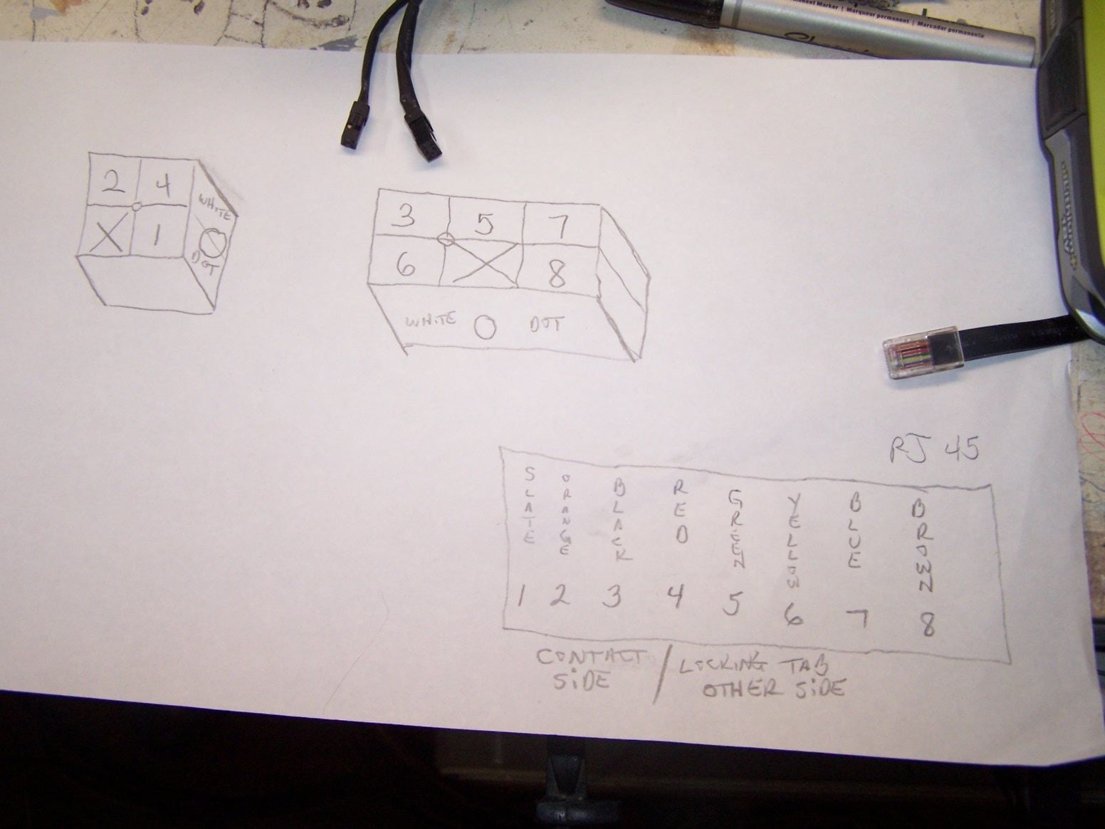
here is the jack and pin layout for the cable
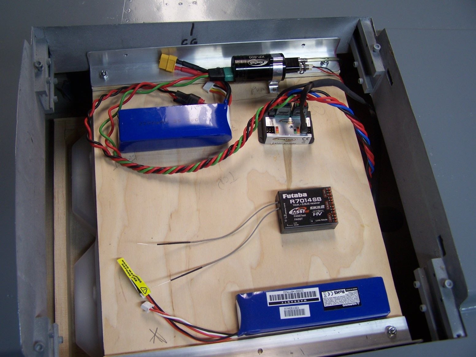
here is some rough layout of where things can go on the tray.
The tray got an air dam to protect the components
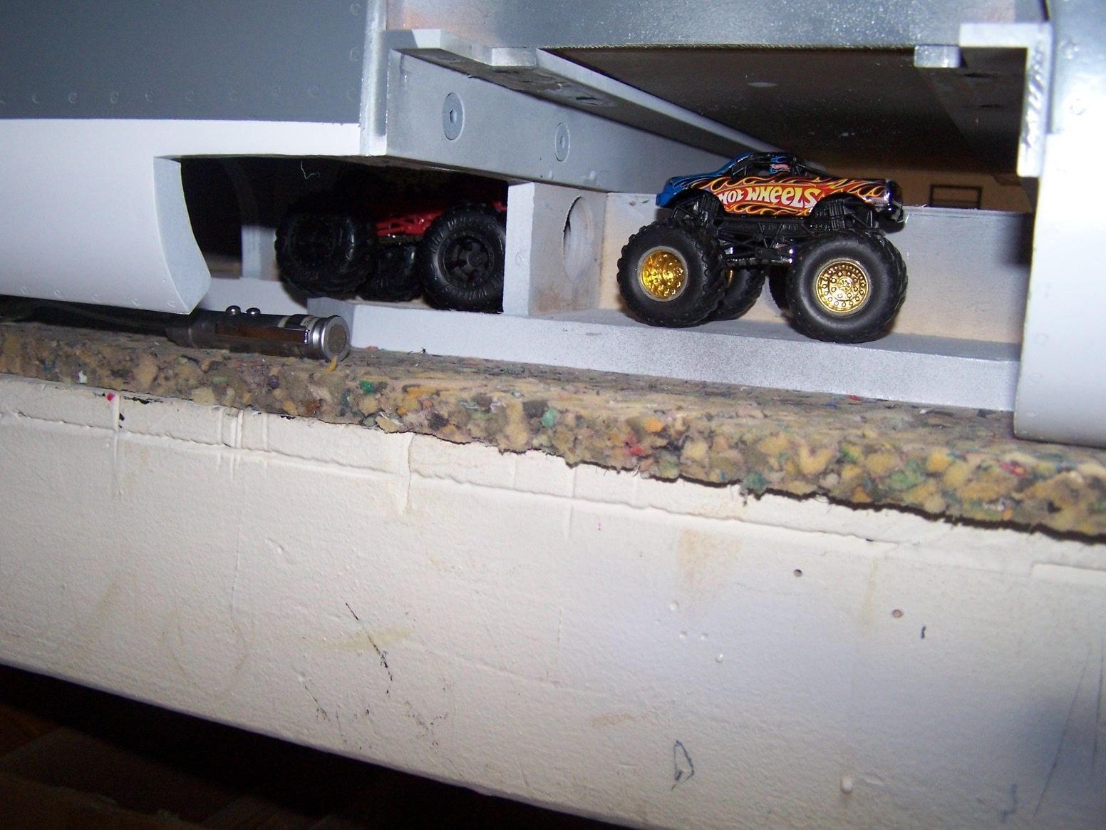
someone is using the landing gear bay as a Hot Wheels monster truck garage
02-10-2019, 08:51 PM
#547
Thread Starter
Join Date: Mar 2009
Location: willow springs , IL
Posts: 1,222
Likes: 0
Received 25 Likes
on
14 Posts

There will be no brass tubes in the tanks. All the lines will be friction fit through the walls of the tanks. The bung is just an access port.
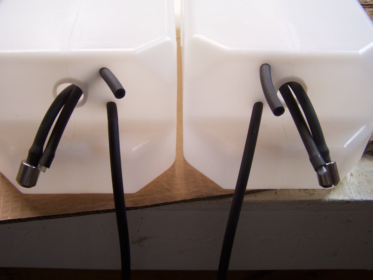
this is everything pushed through the drilled holes. the vent lines are expanded with a segment of plastic tubing.Once pulled back through its very difficult to pull the vent lines out of the tanks.
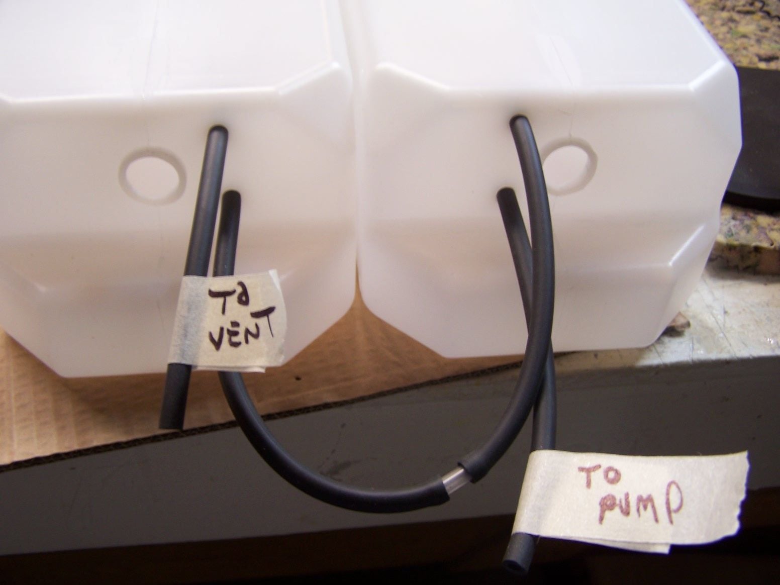
The clunk lines are pushed back in with the length adjusted. One clunk line couples to one vent and they are plumbed in series.
02-10-2019, 09:29 PM
#548
Thread Starter
Join Date: Mar 2009
Location: willow springs , IL
Posts: 1,222
Likes: 0
Received 25 Likes
on
14 Posts
Swap the lines around and the pump can draw from the left or right tank. Thought exercise. If usually flying a left hand pattern (left hand bank) which tank is better for the pump to draw from? Or is there no big difference.
02-11-2019, 01:27 PM
#549
Join Date: Oct 2006
Location: ontario,
CA
Posts: 74
Likes: 0
Received 0 Likes
on
0 Posts
If you run the tanks in series left or right wont matter.As long as the clunk works..You could make the right tank the feed for left pattern and the fuel will sit closer to the centerline in turns..
Last edited by turbofixer; 02-11-2019 at 01:31 PM.
02-11-2019, 03:33 PM
#550
I could be wrong but I think your friction fit lines will be a big mistake. Once the oily fuel and suction from the pump are there I think they will leak. Not only that, I suspect the thin plastic wall of the tank will cut into the lines in short order. Brass tubes through a rubber stopper or thread in fittings glued into a tank are tried and true methods for years. If it could be as simple as friction fit through a tank I'd suspect that would be the norm already.